Analysis of Railway Bridge Steel Sections with
Different Type of Trusses for 32.5 Tonne Axle
Loading
Rohit Gakre1, Rashmi Sakalle2, Nitin Tiwari3
1
P.G. Scholar, 2 Asst. Prof. & H.O.D., 3 Asst. Prof, Department of civil engineering, Truba College, Bhopal, M.P.
Abstract: Bridge is an important structure required for the transportation network. Now a day with the fast innovation in technology the conventional bridges have been replaced by the cost effective structured system. Advanced and most efficient methods are available for analysis and design of these bridges. Different methods which can be used for analysis and design are AASHTO, Finite element method, Grillage and Finite strip method. For this study four different steel truss section are considered they are howe bridge, pratt bridge, warren bridge and k-type bridge sections are considered with 50 metre length supports at the end of the geometry. This has been considered to analyze the bridge for critical load and after analyzing these critical loads, the results will be compared in terms of forces, weight and most importantly cost of each type to determine the most economical section.
Keywords: Bridge, Truss, STEEL structure, Tract, Structural analysis, deflection.
I. INTRODUCTION
An extension is a structure, by which a street, railroad or other administration is extended an obstruction, for example, a stream, valley, other street or railroad line. The superstructure of an extension is the part specifically in charge of conveying the street or other administration. Its format is resolved generally by the aura of the administration to be conveyed. A commonplace arrangement of a bracket connect is a 'through support's setup. There is a couple of support braces associated at base harmony level by a deck that likewise conveys the activity, spreading over between the two brackets.
In this exploration, diverse supports areas are dissected for rail motor and boggie stack according to railroad determinations, to decide the most steady and practical segment which can plan according to Indian measures.
II. LITERATURE SURVEY
1) Osama et. al. (2018) Scaffolds might be built in dynamic seismic regions, where ground shaking or ground disappointments can force impressive earth weights on them. In this examination, the seismic reaction of box ducts was explored tentatively and numerically. A progression of scaled axis tests was performed and exposed to three distinctive quake signals, with various amplitudes and frequencies. Two estimations of course divider thickness and two estimations of sand relative thickness were considered in the trial program. Trial results are displayed regarding examinations of seismic bowing minutes. These outcomes were utilized to adjust and confirm two-dimensional numerical models created utilizing the PC program FLAC. The checked models were then used to research the impact of quake force and recurrence, tallness of soil cover, and duct thickness on the seismic twisting minutes for the diverse course segments. In view of the examination results, outlines are introduced to help in the seismic structure of box courses.
3) Yong-sheng Song et. al. (2016) [11] Examined Using hypothetical displaying joined with checking information, the ordinary dynamic and static practices of a consistent steel support curve railroad connect are assessed. The dynamic conduct includes an effect factor prompted by the activity of running trains, and the static conduct alludes to hub bowing execution and the pressure dissemination among various planes of the bracket. The transverse position, length and speed of running trains are acquainted with direct an investigation of their impacts on the dynamic and static practices of the scaffold superstructure. An auxiliary security assessment is likewise led by examination with the arrangements prescribed by configuration codes and by investigation of outright pressure. It is inferred that three sorts of individuals present diverse unique practices and that the estimation of the effect factor for harmonies B surpasses the arrangement prescribed by the structure codes. Harmonies C present the best proportion of twisting pressure versus hub stretch. A lopsidedness of stress circulation exists among the three planes of the bracket, and the thing that matters is the littlest when trains keep running along the center railroads. Since the train-instigated pressure is impressively lower, the dynamic and static exhibitions of the extension are inside the extent of wellbeing.
4) T.Pramod Kumar, G.Phani Ram (July 2015) This present research's goal was to evaluate the financial significance of the railroad cum street connect. This paper was completed to discover the decrease in expense of development by giving single scaffold to both street and railroads. The investigation and configuration period of the task was finished using STAAD PRO V8i. It was seen that the development of a solitary extension decreased the expense of two separate scaffolds for street and railroads, likewise arrive obtaining issue is diminished to some degree.
A. Outcome Of The Study
The writing survey has proposed that utilization of a limited component displaying of the support superstructure. Along these lines, it has been chosen to utilize STAAD.Pro for the Finite Element Modeling. With the assistance of this product investigation of bracket connect structure has been finished. STAAD.Pro likewise helps in Finite Element Modeling in perspective of that distinctive sort of powers can apply to get the genuine outcomes.
The main objectives of the present study are as follows
1) To analyze and design railway bridge with different types of trusses.
2) To make comparative study of these bridges in terms of forces, torsion, deflection and support reaction.
3) To determine the most cost-effective type of truss section for railway-bridge.
III. MOTIVATION BEHIND STUDY
Truss Girder having 25 to 75 m span generally use as a superstructure for bridges. In this regards, realistic analysis for steel truss bridge for different type of truss sections are considered. In this modern time, such types of analysis are really important to find out the economical section which can be easily prepared in STAAD-Pro for modeling, analysis and design purpose. This motivation has lead to this study on this analysis of moving load as per Indian railway that has to be placed at eccentric and concentric. This study has been considered for the position vehicle loading broad gauge and carried out the critical case values of Bending and Shear Forces.
A. Methodology
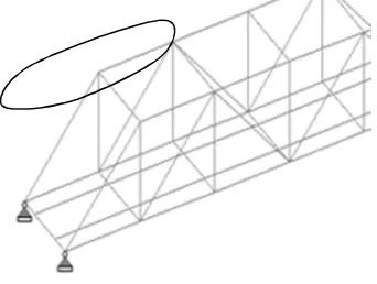
In this methodology, we have used STAAD-Pro software which is based on the application of Finite Element Method. This software is a widely used in the field of structural design and analysis. Now a days this software is quite use friendly for the analysis of different type of structures and to calculate the result at every node & element wise. Analysis for the steel truss members, prepared the conceptual dimension geometry of the superstructure which are shown in figure 1 –
The writing survey has proposed that utilization of a limited component displaying of the support superstructure. Along these lines, it has been chosen to utilize STAAD.Pro for the Finite Element Modeling. With the assistance of this product investigation of bracket connect structure has been finished. STAAD.Pro likewise helps in Finite Element Modeling in perspective of that distinctive sort of powers can apply to get the genuine outcomes.
Four cases have been considered for comparative analysis:
1) First howe bridge 50 m length.
2) Second is bridge geometry is taken as warren truss 50 m length,
3) Third one is bridge geometry is taken as pratt truss 50 m length,
4) Fourth one is bridge geometry is taken as K type truss 50 m length, The following three activities must be performed to achieve that goal -
a) Modeling of the frame using STAAD.Pro.
b) The calculations to decide the explanatory results.
c) Result check is all empowered by devices contained in the framework's graphical environment.
Investigation of railroad steel connect 50 m length extension to development has been considered for the parametric examination of vehicle basic load position according to Indian railroad D.F.C. stacking 32.5 ton stacking standard which are examinations with the assistance of staad star programming.
B. Staad. Pro
STAAD or (STAAD.Pro) is a basic investigation and configuration program at first created by Research Engineers International in Yorba Linda, California. Later in year 2005-06, Research Engineer International was possess by Bentley Systems. STAAD.Pro can take care of regular issue like tremor investigation, wind examination and weakling examination and so on . This sort of issue can be fathomed by STAAD.Pro alongside codal areas. In addition STAAD.Pro has a superior favorable position than the manual estimation as it gives more correct outcome than the manual count. STAAD.Pro was conceived tremendous. It is the most well known instrument utilized in present days. Mostly it is performing investigation configuration works. There are four stages utilizing STAAD.Pro to achieve the objective.
1) Get ready the input file.
2) Analyse the input file.
3) Post processing the results and verify them.
4) Send the analysed result to design as per codal provinces.
a) Get ready the input file: First of all portray the structure. These section includes geometry, the materials, cross sections, the support conditions.
b) Analyse the input file-
i) Now, sure that we are using STAAD.Pro syntax. Else it will error.
ii) And also sure that all the inputs are inserted are correct in structure. Else it will indicate error.
iii) In end verify our output data to make sure that the input data wasgiven properly.
c) Post processing the results and verify them.
i) Checking the result take place in POST PROCESSING Mode.
ii) Initially choose the output file that analyse (like various loads or load combination) .Then it will indicate the results.
d) Send the analysed result to design as per codal provinces i) After analysis take the analysis results to be design.
ii) Than Run the analysis it will show the full design structure.
C. Modeling of bridge frames
Following geometrical properties has been considered with materials in modeling:-
1) Geometric Properties
Table no 1: Property of material
S.NO Description Value
1 Steel table Standard sections
2 Young’s modulus of steel, Es 2.17x10⁴ N/mm2
3 Poisson ratio 0.17
4 Tensile Strength, Ultimate Steel 505 MPa
5 Tensile Strength, Yeild Steel 215 MPa
6 Elongation at Break Steel 70 %
7 Modulus of Elasticity Steel 193-200 GPa
The Bridge is of structural plan in X direction is 50 and in Z & Y direction is 4 meter respectively.
2) Design steps for railway steel Bridge
a) Dead Load: The dead load of structure is not known before it is designed. It is assumed in conventional method as per experience. After designing, the assumed D.L. is compared with the actual D.L. if the assumed D.L.is less, than it is revised and structure is redesigned. or using analysis tool it can be calculated automatically.
b) Live load:
i) EUDL: it depends upon the length of rail.
ii) B.M.: For maximum bending moment in elements resisting bending (As per railway code appendix II)
iii) S.F.: For maximum forces in elements resisting shear at sections (As per railway code appendix II)
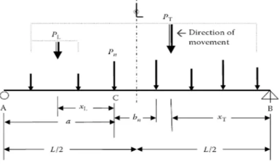
[image:4.612.156.443.412.581.2]c) Actual Axle Load as per Railway code (Appendix-I)
Fig 2: Concentrated moving load on the superstructure
d) Temperature load: Provision of temperature load is applied to determine the effect of temperature difference.
e) Vehicle collision load: As per railway code provision Appendix-III, load applied is 32.5 tonne axle load. With this load for collision of vehicle analysis effect of elastometric bearings is also considered.
f) Analysis: A global analysis is required to establish the maximum forces and moments at the critical parts of the bridge, under the variety of loading conditions. As well as the dynamic interaction between the train and the bridge, there may be track/bridge interaction.in resisting longitudinal loads.
D. Material Properties
[image:5.612.41.523.127.717.2]In this problem standard material properties are considered which is given below in table no.2
Table no 2 :Description of Structure
S.NO Description Value
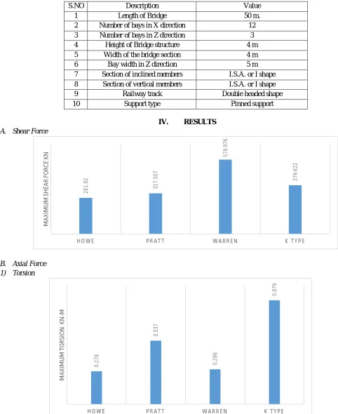
1 Length of Bridge 50 m.
2 Number of bays in X direction 12 3 Number of bays in Z direction 3
4 Height of Bridge structure 4 m
5 Width of the bridge section 4 m
6 Bay width in Z direction 5 m
7 Section of inclined members I.S.A. or I shape 8 Section of vertical members I.S.A. or I shape
9 Railway track Double headed shape
10 Support type Pinned support
IV. RESULTS
A. Shear Force
B. Axial Force 1) Torsion 2 8 1 .9 2 3 1 7 .5 0 7 5 7 8 .9 7 6 3 7 9 .6 2 2
H O W E P R A T T W A R R E N K T Y P E
M AX IM U M S H E AR F O R C E K N 0 .2 7 8 0 .5 3 7 0 .2 9 6 0 .8 7 9
H O W E P R A T T W A R R E N K T Y P E
C. Deflection
[image:6.612.70.513.88.546.2]D. Support Reaction
Table 3 Comparative results
7
.9
4
8
7
.6
6
6
2
.9
3
5
5
.2
0
4
H O W E P R A T T W A R R E N K T Y P E
M
AX
IM
U
M
D
EF
LE
C
TI
O
N
M
M
1537.5 1538.25 1539
howe pratt warren k type
E. Steel Structure Weight
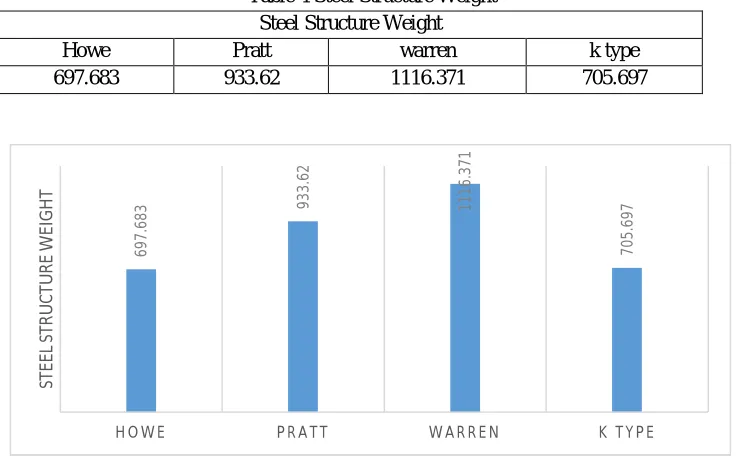
Magnitude of maximum stress for various forms of truss has been plotted in figure number 4. It is observed that warren truss type bridge structure will be costlier for same loading as compared to other cases whereas Howe type bridge will be economical in comparison to other cases.
Table 4 Steel Structure Weight Steel Structure Weight
Howe Pratt warren k type
697.683 933.62 1116.371 705.697
Steel Structure Weight
F. Internal Analysis Of Members For Optimization 1) Inclined Member
[image:7.612.131.499.150.379.2]Inclined members
Table 5: Inclined members
Truss Section
Howe truss I.S.A. LD 60x60x6
Pratt truss I.S.A. LD 100X100X8
Warren truss I.S.A. LD 140X100X10
K-type I.S.A LD 80X60X8
2) Inferences: In the table above, it is clearly stated that there is a variation in section in different types of trusses as due to their geometry load distribution is varying thus results shows that Howe truss prefers minimum section as compared to other after optimization of steel sections.
6
9
7
.6
8
3 93
3
.6
2
1
1
1
6
.3
7
1
7
0
5
.6
9
7
H O W E P R A T T W A R R E N K T Y P E
ST
E
E
L
ST
R
U
C
TU
R
E
W
EI
GH
G. Vertical Members
[image:8.612.140.459.75.354.2]Vertical member
Table 6: Vertical members
Truss Section
Howe truss I.S.A. LD 140x140x10
Pratt truss I.S.A. LD 180X180X10
Warren truss I.S.A. LD 180X120X10
K-type I.S.A LD 140X100X8
1) Inferences: In the table above, it is clearly stated that there is a variation in section in different types of trusses as due to their geometry load distribution is varying thus results shows that Howe truss prefers minimum section as compared to other after optimization of steel sections.
H. Horizontal Top Member
[image:8.612.229.400.422.551.2]Horizontal top member
Table: 7 Horizontal top member
Truss Section
Howe truss I.S.A. LD 140x140x100
Pratt truss I.S.A. LD 180X180X10
Warren truss I.S.A. LD 180X120X10
K-type I.S.A LD 140X100X10
V. CONCLUSION
As discussed in the last chapters, we have considered four vehicle load cases along with dead load & rail load for the Steel bridge for analysis by using Staad-Pro software. Following are the salient conclusions of this study-
A. Deflection
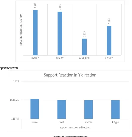
For the case of deflection analysis, we have analysis number of cases for critical the values and observed that out of the four cases Howe bridge gives maximum values i.e. 7.948 mm
B. Support Reaction
For the case of reaction analysis, we have analysis number of cases for critical the values and observed that out of the four cases Howe bridge gives maximum values i.e. 1538.05 KN (Y).
C. Torsion
For the case of torsional analysis, we have analysis number of cases for critical the values and observed that out of the four cases K-type bridge gives maximum values i.e. 0.879 KN-m
D. Shear Force
For the case of Shear force analysis, we have analysis number of cases for critical the values and observed that out of the four, warren type bridge gives maximum values which means it is the most unbalance type bridge in comparison i.e. 578.976 N.
E. Axial Force
For the case of Axial force analysis, we have analysis number of cases for critical the values and observed that out of the four Pratt type bridge gives maximum values whereas owe has least value i.e. 4583.729 KN
F. Steel Structure Weight
As India is a developing country therefore there is a need of economical sections to have a cost-effective design to bear same loading in lesser cost. Here in our study out of all four cases Howe type truss bridge shows least values which mean for the same loading it will take less weight of construction material which makes it more economical than others. i.e. 697.683 Newton
G. Summary
In this comparative study, it is concluded that K-type and Pratt type truss bridge shows comparatively more stiffness and stability to resist load whereas in cost comparison Howe type truss bridge is more economical; thus, it can be concluded from our study that in resisting load K and Pratt type are more effective and in terms of cost Howe type is more economical whereas K type is second best economical type. Therefore, it can be justifying that K-type truss bridge will be overall more suitable than other cases.
REFERENCES
[1] C.Neeladharan, Vinitha.V, Saranya.S and Priya.Bn “Analysis and Design of Multi-Storeyed Building by Steel Concrete Composite Structure” IJIRST – International Journal for Innovative Research in Science & Technology, ISSN 2349-6010, Volume 3, Issue 11 April 2017.
[2] Yong-sheng Song, You-liang Ding, Han-wei Zhao, Gao-xin Wang, Ai-qun Li and Bao-ya Cao, “Structural behavior analysis of a continuous steel truss arch railway bridge integrating monitoring data” World congress on Structures Congress, 2016
[3] Vikas Srivastava, Ashhad Imam and Zaman Abbas Kazmi, “Analysis and Design of Box Type Minor Railway Bridge” International Journal of Civil Engineering and Technology· July 2017.
[4] Osama Abuhajar, Hesham El Naggar, and TimNewson, “Seismicsoil–culvertinteraction”, Canadian Geotechnical Journal· April 2015.
[5] Bridge rules (Railway Board). Rules specifying the loads for design of super structure and substructure of bridges and for assessment of the strength of existing bridges.
[6] Indian railway standards-Steel Bridge Code Indian railway standard code of practice for the design of steel or wrought iron bridges carrying rail, road or pedestrian traffic.
[7] IRC: 6-2014 Section –II (Loads and Stesses) standard specifications and code of practice for road bridges.
[8] IRC: 21 Section –III Cement Concrete (plain and reinforced) standard specifications and code of practicefor road bridges. [9] Coenraad ESVELD and Valéri MARKINE, SLAB TRACK DESIGN FOR HIGH-SPEED
[10] IRS Concrete Bridge Code : 1997 Code of practice for plain, Reinforced & prestressed concrete for general bridge construction.
[11] IRS Bridge Rules: 2008 Rules specifying the loads for Design of super-structure and sub-structure of Bridges and for assessment of the strength of Existing bridges.
[13] EN 1991-2 Euro code for traffic loads on bridges.
[14] IS-456:2000 Code of practice for plain and reinforced concrete. [15] IS-875 Code of practice for design loads.
[16] IS-432 Part 1-1982 Mild steel and medium tensile steel bars.
[17] IS-1786:2008 High strength deformed steel bars and wires for concrete reinforcement - Specification. [18] IS-1893:2002 Criteria for earthquake resistant design of structures.