Eutectic Growth in Laser Cladding of Zr-Coating
on AZ91D Magnesium Substrate
T. M. Yue
1, H. Xie
1, X. Lin
1,+and H. O. Yang
21Advanced Manufacturing Technology Research Centre, Department of Industrial and Systems Engineering,
The Hong Kong Polytechnic University, Hung Hom, Kowloon, Hong Kong, P. R. China
2State Key Laboratory of Solidification Processing, Northwestern Polytechnical University, Xi’an 710072, P. R. China Zr-bearing coatings were fabricated on an AZ91D magnesium substrate by means of a two-step method. First, pure zirconium powder was plasma sprayed on the substrate and, subsequently, laser cladding was performed on top of the spray deposited layer. The process led to the formation of a zirconium coating containing zirconia. The coating comprises three layers; on top of the substrate is the plasma sprayed layer, followed by the laser re-melt layer andfinally an outermost laser-clad layer. The microstructure and phase of the coating were studied. The results show that rapid solidification occurred in the laser-clad layer and resulted in a directional eutectic cellular and eutectic dendrite growth of (Zr)+ZrO2. The maximum velocity for co-operative lamellar growth of the (Zr)+ZrO2eutectic and its corresponding lamellae spacing were
calculated based on the TMK model. [doi:10.2320/matertrans.M2012048]
(Received February 10, 2012; Accepted March 8, 2012; Published April 25, 2012)
Keywords: laser cladding, zirconium, coating, magnesium, eutectic growth
1. Introduction
Magnesium and its alloys are not only attractive for engineering applications but they are also considered to be appropriate metals for biomedical implants and devices. Indeed, much effort has been devoted to developing magnesium and its alloys as potential degradable biomate-rials1,2) due to their low density, high specific strength and
appropriate elastic modulus of about 40 GPa, which is much lower than most of the currently used metallic implant materials and is close to that of human bone. For a bio-implant material, a too high stiffness is not desirable, the problem being that a stiff implant would shield the nearby bone from mechanical stresses. This results in a type of disuse atrophy, bone resorbs, and subsequently loosening of the implant. In fact, biodegradable magnesium and its alloys have been explored for various surgical applications for more than one hundred years,3) and as early as the beginning of the twentieth century, magnesium was reported as having been used to secure a fracture in a human leg.4) Although the attempt failed, as the metal corroded too quickly, interest in using Mg for orthopaedic implants has not gone cold but remains strong. In fact, in recent years, there has been considerable interest in exploring the use of Mg and its alloys as degradable biomaterials. This is largely due to test results which found that the corrosion rate of Mg and its alloys, when tested in physiological environments, can be modulated to an acceptably low level through the use of high purity Mg, or new alloying systems and surface treatments.58)On the other hand, it is considered that if the corrosion problem of Mg can be satisfactorily resolved, Mg and its alloys may become good candidates for long-term implantation applications.
To address the corrosion problem of Mg with a biocompatible coating, a previous study has shown that laser cladding of Zr on Mg is a promising solution.9)A high wear
and corrosion resistant Zr-based graded coating can be fabricated on AZ91D magnesium alloy by laser forming. Zr
was employed because the metal and its oxides display excellent electrochemical properties and biocompatibil-ity.10,11)The Zr-based graded coating has superior corrosion resistance when compared to the uncoated material.9) The corrosion current density measured for the coating was three orders of magnitude lower than that of the untreated AZ91 material when tested in a simulated body fluid, namely Ringer’s solution.
Notwithstanding the fact that Zr-based coatings can be fabricated on Mg alloys using laser cladding, the main challenges of overcoming the high chemical reactivity, and the relatively low melting and boiling points of Mg alloys cannot be easily overcome. It was found that there is only a very narrow processing window for producing good quality coatings. Recognizing this, the research has adopted a two-step approach to circumvent these problems. The two-two-step technique involved plasma spraying a Zr-coating on the Mg substrate first, and then a thicker Zr-coating was further deposited on top using laser cladding. Such a technique has been successfully employed to deposit stainless steel on ZK60/SiC Mg composite.12)Using this technique can avoid
excessive melting and boiling of the Mg substrate in the course of laser cladding. Laser cladding is required to increase the coating thickness because normally it is difficult to obtain good quality thick coatings using plasma spraying alone. This study focuses on the microstructure of the Zr-based coating formed under multi-layer cladding conditions.
2. Experimental Procedures
For the spraying of zirconium on the AZ91D substrate (nominal composition 9 mass%Al, 1 mass%Zn, balance Mg), a relatively low-velocity plasma spray system was employed. It was designed to provide a uniform heating effect on the metal powder with high deposition efficiency.13)The plasma
spray parameters used are given in Table 1. The Zr powder for spraying was commercially pure with a mesh size of 200 300. The Zr powder was dried using a vacuum oven for 24 h prior to the experiment. After plasma spraying, laser cladding
+Present address, Northwestern Polytechnical University
was employed to further deposit Zr on the AZ91D substrate using a 4 kW continuous wave CO2laser from Prima North
America. The laser was equipped with a four-axis numerical control working table and a lateral powder feeder nozzle. Laser cladding was conducted inside a controlled-atmosphere glove box, where high-purity argon gas was continuously supplied at a flow rate of 10 litres per minute during the experiment. In the course of laser cladding, the laser beam was directed onto the plasma sprayed coating to create a shallow molten pool, and the Zr powder was delivered into the pool using a lateral powder feeder with the aid of aflow of argon gas. The feeding angle between the substrate and the powder feeder nozzle was 60°. The Zr powder was melted and subsequently re-solidified to form a laser-clad track. In order to create a coating, multi-tracks were produced with an overlapping percentage of 30%, and two layers were deposited. The total thickness of the coating was about 200 µm. A summary of the laser processing parameters is given in Table 2.
The phases of the laser-clad layer, the AZ91D substrate and the plasma sprayed layer were determined with a Philips X’Pert X-ray diffractometer (XRD) using Cu-K¡ radiation at 40 kV and 30 mA. The specimens for microscopic study were ground with a series of emery papers and then finally polished with 0.5 µm diamond abrasives. To reveal the microstructure, the specimens were etched in a regent of 10 ml HF+20 ml HNO3+80 ml H2O. The microstructure
was studied using a JEOL JSM-6490 scanning electron microscope equipped with energy dispersive X-ray spec-troscopy (EDX).
3. Results and Discussion
3.1 Phases and microstructure of the Zr-coating
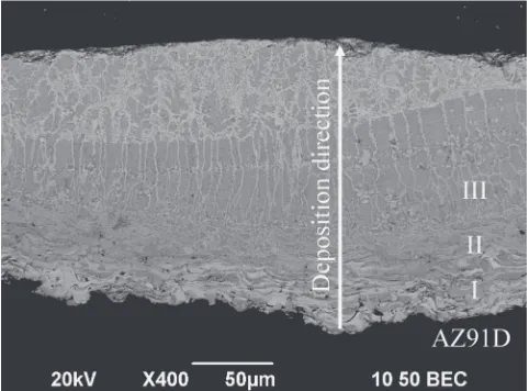
Figure 1 shows a cross-section of the Zr coating, which comprises a plasma-spray layer and a laser-clad layer with a total coating thickness of about 200 µm. The XRD results for the AZ91D substrate, the as-sprayed specimen and the laser-clad specimen are presented in Fig. 2. For the as-sprayed specimen, the coating consists three phases, i.e., a Zr solid solution (Zr), ZrO2 and Zr3O. After laser processing, only
(Zr) and ZrO2were detected in the laser-clad coating. These
results show that both the plasma spray and the laser cladding
have led to the oxidation of Zr. In addition to the XRD analysis, an EDX analysis of elements was also performed across the thickness of the coating and the results are shown in Fig. 3. The EDX results show that there was no sign of mixing of the substrate material and the Zr overlay coating. Broadly speaking, the microstructure of the coating (Fig. 1) can be divided into three zones, i.e., the as-sprayed zone (I), the laser re-melted zone (II) and the laser-clad zone (III).
Figure 4 presents the microstructure of the laser-clad coating in greater detail at various locations along the deposition direction of the laser cladding. Figure 4(b) shows the microstructure of the un-remelted plasma spray layer close to AZ91D substrate, and the layer consists offlattened lamellae of grey and white colours. An EDX analysis shows that the grey lamellae have a higher oxygen content than those of the white lamellae. These results together with the XRD results (Fig. 2) suggest that the former should be mainly corresponding to zirconium oxide ZrO2, while the
[image:2.595.307.548.71.249.2]latter is an O-rich solid solution (Zr). Lying above the plasma spray layer is a narrow zone of re-melted plasma spray structure (Fig. 4(c)), where the crystal growth of fine zirconium oxides occurred. The re-melted zone was formed when the laser was used to produce a melt pool upon which Table 1 Plasma spray parameters.
Plasma gas Ar/H2
[image:2.595.46.291.84.149.2]Gasflow (l/min) 50 Arc voltage (V) 60 Arc current (A) 600 Spray distance (mm) 130
Table 2 Laser cladding parameters.
Laser power (kW) 0.81.0 Scan velocity (mm/s) 5 Laser beam diameter (mm) 3 Powder feeding rate (g/min) 1.1
Fig. 1 A cross-section of the laser-clad specimen.
20° 30° 40° 50° 60° 70° 80° 90°
[image:2.595.44.293.189.240.2] [image:2.595.311.541.285.464.2]laser cladding was performed. Figures 4(d) and 4(e) show that some interesting microstructural changes occurred along the deposition direction. Initially, the crystal exhibited a kind of directional two-phase eutectic cellular growth (Fig. 4(d)), and further towards the surface of the coating, a type of two-phase eutectic dendritic growth of (Zr) and ZrO2 occurred.
For the cellular growth, a cooperative lamellar eutectic structure was obtained, while a mix of lamellar and anomalous eutectic structure was observed for the dendritic
growth. The change from a cooperative lamellar to an anomalous eutectic structure is discussed in the following section.
3.2 Lamellar to anomalous eutectic growth
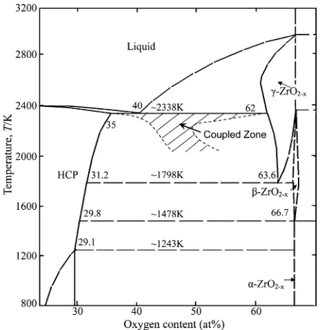
The equilibrium phase diagram of ZrO shown in Fig. 5 indicates that a two-phase eutectic structure is obtained at a composition of about 40 at%O. When considering the oxygen contents in locations IIIA and IIIB marked in Fig. 4, they were measured to be 58.03 at% and 53.99 at%, respectively, and are much higher than that of the eutectic composition of 40 at%O. According to the phase diagram, a hyper-eutectic structure would form at such high oxygen content, in that the
£-ZrO2¹xphase, as the primary phase, would solidifyfirst and
very likely with a dendritic morphology. However, Fig. 4 shows that under the laser cladding condition, the ZrO melt initially solidified in the form of lamellar eutectic cells (Fig. 4(d)) and then a mix of lamellar and anomalous eutectic structure (Fig. 4(e)). Such an off-eutectic cooperative lamel-lar growth, perhaps, can be explained using the proposition of a coupled zone of eutectic of Kurz.16)It is possible that there
is a coupled zone, representing a growth of the composition/ temperature region, where the interface undercooling of eutectic growth is lower than that of the £ phase dendrite growth. Under such a growth condition, a cooperative lamellar eutectic structure can be obtained (Fig. 4(d)). The formation of a cooperative lamellar eutectic structure at a higher oxygen content than the equilibrium eutectic compo-sition suggests that, under the present laser cladding condition, a coupled zone of eutectic is located below the equilibrium eutectic temperature.
With regard to the transition of cellular growth (Fig. 4(d)) to a two-phase eutectic dendritic growth (Fig. 4(e)), it is mainly controlled by the growth velocity of the eutectic cells and the constitutional undercooling ahead of the solid/liquid interface. During the course of rapid solidification, both the Fig. 4 (a) Secondary electron image of a laser-clad coating (etched),
backscattered images showing more details of the microstructure, (b) regionI, (c) regionIIand (d) regionIIIA, and (e) regionIIIB.
Fig. 5 A re-constructed ZrO binary phase diagram based on Arroyave et al.14)and Wanget al.,15)in which a possible coupled zone is included.
[image:3.595.65.275.68.232.2] [image:3.595.311.543.69.308.2] [image:3.595.52.285.272.626.2]growth velocity of the eutectic cells and the constitutional undercooling ahead of solid/liquid interface increased gradually as the solidification front advanced towards the surface of the deposition. As this condition prevails, the solid/liquid interface would become unstable and lead to the development of eutectic dendrite growth.
To understand the eutectic growth of (Zr)+ZrO2¹x, the
growth condition was analysed using the TMK model,17) which predicts eutectic growth morphology under rapid solidification conditions. Using this model, the eutectic interface temperature can be calculated by the relation,
Te¼TeutþTe ð1Þ
where Teut is the nonequilibrium eutectic temperature, and
¦Teis the nonequilibrium eutectic undercooling, which can
be found from the following two equations.
e2V ¼aL=QL ð2Þ
eTe¼maL 1þPþð@P=@P Þ
ð3Þ
where eis the lamellar spacing, and the definitions of the
other terms are as follow.
aL¼2 aL1 fm1 þ
aL 2 ð1fÞm2
=Fðk¹Þ ð4Þ
QL¼ 1k¹
fð1fÞDL Pþ @P @
ð5Þ
m¼mm1m2
1þm2Fðk¹Þ ð6Þ
Fðk¹Þ ¼1þk0kð11lnkðk¹=k0ÞÞ
0 ð7Þ
k¹ ¼k10þþV=VV=VD
D ð8Þ
Pþ@P@ ¼X1 n¼1
1
n³ 3
½sinðn³fÞ2
ffiffiffiffiffiffiffiffiffiffiffiffiffiffiPn
1þp2 n
p
1þ2k¹
" #2
Pn
ffiffiffiffiffiffiffiffiffiffiffiffiffiffi
1þp2 n
p ð9Þ
Pn¼2Pn³
e ð10Þ
where f is the volume fraction of the (Zr) phase associated with the (Zr)+ZrO2¹xeutectic,aL1 andaL2 are the capillarity
constants of the (Zr) and ZrO2¹x phases, Pe is the solutal
Peclet number for eutectic growth, m1 and m2 are the
equilibrium liquidus slopes of the (Zr) and ZrO2¹x phases,
respectively. VD¼Di=a0 is the interface diffusivity speed, witha0being the characteristic interface thickness andDithe
[image:4.595.306.549.94.243.2]solute diffusivity across the interface. The physical param-eters used for the calculation of the interfacial temperature and the maximum coupled growth velocity are given in Table 3, and the results are presented in Fig. 6, in which, a maximum growth velocity of 3.2 mm/s with a sudden drop in eutectic interface temperature is predicted. The results suggest that beyond this maximum growth velocity, a cooperative lamellar eutectic growth cannot be maintained, and the development of irregular anomalous eutectic structures would set in. This phenomenon was found to occur as solidification proceeded towards the surface of the coating (Fig. 4(e)), where the maximum growth velocity
was exceeded. The predicted maximum growth velocity (3.2 mm/s) for cooperative lamellar eutectic growth of (Zr) and ZrO2¹xis considered to be acceptable, since the growth
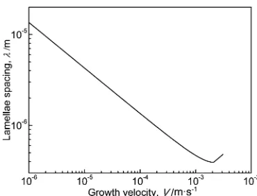
velocity increased from near zero at the bottom of the melt pool to approaching a maximum of 5 mm/s (corresponding to the laser scan velocity) at the top of the coating. Hence, it is believed that increasing the laser scan velocity beyond 5 mm/s would further inhibit the growth of the cooperative lamellar eutectic and on the other hand would favour the development of more anomalous eutectic structures. In addition to the prediction of the maximum growth velocity for the lamellar eutectic, the lamellae spacing of the eutectic cells in relation to growth velocity was also determined using the TMK model. The results show that at a maximum growth velocity of 3.2 mm/s, a lamellae spacing of 0.47 µm is obtained (Fig. 7), which is considered to agree reasonably well with the measured mean value of 0.73 µm.
4. Conclusions
A zirconium coating containing zirconia was successfully fabricated on a commercial AZ91D substrate by a two-step method of plasma spraying and laser processing. Broadly speaking, the coating comprises three layers, i.e., a plasma sprayed layer, a remelted plasma spray layer and a laser-clad layer. In the laser-clad layer, two interesting features have been observed; the directional growth of (Zr)+ZrO2eutectic
[image:4.595.315.522.256.403.2]cells and a two-phase (Zr)+ZrO2 eutectic dendritic growth
Table 3 Physical parameters used for the calculation of interfacial temper-ature, growth velocity, and lamellae spacing.
Eutectic composition (at%O) 40 Eutectic temperature (K) 2338 Volume fraction of (Zr) phase 0.185 Length of eutectic line (at%O) 16.15 Equilibrium liquidus slope of (Zr) phase (K/at%) 8.937 Equilibrium liquidus slope of ZrO2¹xphase (K/at%) 42.483
Capillarity constant of (Zr) phase (mK) 1.73©10¹7
Capillarity constant of ZrO2¹xphase (mK) 5.52©10¹7
Prefactor of diffusion coefficient (m2/s) 2.057©10¹7
Activation energy for solute diffusion (J/mol) 9.375©104
Equilibrium partition coefficient of (Zr) phase 0.69 Equilibrium partition coefficient of ZrO2¹xphase 0.175
[image:4.595.69.293.337.560.2]towards the top of the coating. The solidification of cooperative lamellar eutectic cells is considered to be a result of an off-eutectic composition growth, and can be explained using the proposition of a coupled zone of eutectic of Kurz.16) The TMK model was used to predict the maximum velocity for cooperative lamellar growth of (Zr)+ZrO2 eutectic, as well the lamellae spacing of the
eutectic structure, and the result on the spacing agrees reasonably well with the measured value.
Acknowledgements
The work described in this paper was fully supported by a grant from the Research Grants Council of the Hong Kong
Special Administrative Region, China (Project No. PolyU 534508). The authors would also like to thank the Hong Kong Polytechnic University, the Northwestern Polytechnical University and the Xi’an Jiaotong University for providing the research facilities.
REFERENCES
1) M. P. Staiger, A. M. Pietak, J. Huadmai and G. Dias:Biomaterials27 (2006) 17281734.
2) M. Niinomi (ed.): Metals for Biomedical Devices, (Woodhead Publishing Ltd., 2010) pp. 379404.
3) F. Witte:Acta Biomater.6(2010) 16801692.
4) A. Lambotte: Bull. Mém. Soc. Nat. Chir.28(1932) 13251334. 5) M. P. Staiger, A. M. Pietak, J. Huadmai and G. Dias:Biomaterials27
(2006) 17281734.
6) F. Witte, F. Feyerabend, P. Maier, J. Fischer, M. Stormer, C. Blawert, W. Dietzel and N. Hort:Biomaterials28(2007) 21632174. 7) B. Heublein, R. Rohde, V. Kaese, M. Niemeyer, W. Hartung and A.
Haverich:Heart89(2003) 651656.
8) E. Zhang, L. P. Xu and K. Yang:Scr. Mater.53(2005) 523527. 9) T. M. Yue and K. J. Huang:Mater. Trans.52(2011) 810813. 10) Y. Tsutsumi, D. Nishimura, H. Doi, N. Nomura and T. Hanawa:Acta
Biomater.6(2010) 41614166.
11) Y. Han, Y. Y. Yan, C. G. Lu, Y. M. Zhang and K. W. Xu:J. Biomed. Mater. Res. Part A88A(2009) 117127.
12) T. M. Yue, Q. W. Hu, Z. Mei and H. C. Man:Mater. Lett.47(2001) 165170.
13) C. J. Li and B. Sun:Mater. Lett.58(2004) 179183.
14) R. Arroyave, L. Kaufman and T. W. Eagar:Calphad26(2002) 95118. 15) C. Wang, M. Zinkevich and F. Aldinger:Calphad28(2004) 281292. 16) W. Kurz and D. J. Fisher: Fundamentals of solidification, 4th ed.,
(Trans. Tech. Publications, 1998) pp. 108110.
17) R. Trivedi, P. Magnin and W. Kurz:Acta Metall.35(1987) 971980. Fig. 7 Relationship between eutectic lamellae spacing and growth velocity
[image:5.595.75.260.67.208.2]