Solidi
fi
cation Structure and Casting Defects in High-Speed Twin-Roll Cast
Al
2 mass
%
Si Alloy Strip
Min-Seok Kim
+and Shinji Kumai
Department of Materials Science and Engineering, Tokyo Institute of Technology, Yokohama 226-8502, Japan
Al2 mass%Si alloy, which has wide freezing temperature range, was cast using a laboratory-scale vertical-type high-speed twin-roll caster. The solidification structure and several kinds of casting defects were examined using OM, SEM and SEM-EDS. The results showed that the unstable melt pool condition could cause the surface defects such as the ripple mark,“un-shiny”zone and the inverse segregation. In the present nozzle type, constructing a stable high melt pool level was seemed to be essential to obtain a sound strip with no defect on the strip surface. A large-scale internal cracking along the casting direction was also observed in the high-speed twin-roll casting of aluminum alloy. The present results revealed that the cracking was related to distribution of the residual liquid in the central band region, which could be controlled by the roll separating force near the roll nip. It is considered that the roll separating force caused the shear localization in the central band region and promoted a formation of continuous liquidfilm in the shear localized region. The liquidfilm was a cause of the internal cracking when the strip passed through the roll nip. [doi:10.2320/matertrans.L-M2013824]
(Received December 19, 2012; Accepted June 20, 2013; Published September 6, 2013)
Keywords: twin-roll casting, aluminumsilicon alloy, surface defect, ripple mark, inverse segregation, internal cracking, grain structure, shear localization
1. Introduction
Ever since a twin-roll continuous caster wasfirstly devised by Bessemer in the middle of nineteenth century,1) many researchers and manufacturers have tried to apply the caster to the thin strip production because it was a quite attractive process through which the production steps could be greatly reduced.2,3) Generally, twin-roll casters can be roughly
divided into three types depending on the casting roll arrangements: vertical, horizontal and inclined casters. Several melt feeding systems are devised to achieve stable casting conditions.4)
In steel industry, since the first commercial applications were developed in the middle of twentieth century2) considerable progress has been attained in developing a twin-roll strip casting process with high casting speed.5,6) In aluminum industry, the twin-roll casting operation started around the same time by Hunter and Lauener.2) However, until recently, the twin-roll casting for aluminum sheet production was limited mostly to horizontal-type.4,7) The
horizontal-type casters are generally operated at very low casting speed in comparison with the vertical-type caster. In addition, the process is available only for alloys with narrow freezing temperature range.7)
About a decade ago, Haga et al. developed a vertical-type caster in aluminum sheet fabrication with remarkably increased casting speed.8,9)They used pure copper rolls with
no lubricant on the roll surface to remove heat effectively. A feeding nozzle was installed over the rolls to introduce a large hydrostatic pressure. Various kinds of aluminum alloy strips such as AlMgSi based,1013)and AlSi alloys14)were fabricated by using the caster. The cast strip with refined solidification structure due to the high cooling rate improved toughness and formability.1518)
However, a severe problem arose in the high-speed twin-roll cast alloy with a wide freezing temperature range.11,12,14)
Large-scale cracking occurred in the mid-thickness region during the strip casting. Fractography of the crack surface revealed that a shrinkage cavity was the primary reason for the cracking.11,14)This suggested that distribution of residual liquid in the mid-thickness region when the strip goes through the roll nip was a dominant factor controlling the internal cracking.
In order to investigate the influence of the freezing temperature range on the internal cracking, the thickness and microstructure of AlMgSi based 6022 alloy strip with a wide freezing temperature range was compared to those of the pure aluminum strip with no freezing temperature range.11) The thickness of the 6022 strip was much larger than that of pure aluminum strip. Moreover, a thick central band consisting of fine globular grains was formed only in the 6022 alloy strip, and a large internal cracking was observed in the central band region. These differences were related to change in solidification manner: cellular growth with planar growth-front in pure Al and dendritic growth with mushy-type growth-front in the 6022 alloy. The formation of relatively thick solidifying shell in the mushy-type growth contributes to the large strip thickness. It was also thought that twiggy dendrite branches in the mushy layer of the growth-front could be fragmented when two solidifying shells encountered near the roll nip. As a result, the fragmented grains and somefloating grains in the melt were concentrated in the mid-thickness region of the cast strip and formed a band structure. Consequently, solidification of the remained liquid in the central band region immediately after the strip went through the roll nip was considered to be a main reason of the internal cracking.
More precise investigation was made to study the influence of the freezing temperature range on the strip thickness and the internal cracking using AlSi binary alloys.14) For this
purpose, hypo-eutectic binary AlSi alloys with various Si contents were cast under the same casting conditions. The strip thickness changed distinctly with changing the Si compositions, and the largest strip thickness was obtained in
+Graduate Student, Tokyo Institute of Technology
Al2 mass% Si strip. Microstructure observation found that whole strips exhibited band structures, which were macro-scopically distinguishable from the outer shells in the mid-thickness region of the cast strip. The internal cracking was observed in the strip with 12 mass% Si compositions. This composition range (12 mass%Si) roughly corresponded to the composition of the widest freezing temperature range in equilibrium AlSi phase diagram. In these strips, the thick central band consisted offine globular grains and very small amount of AlSi eutectic phase at the inter-grain region. The amount of the eutectic phase corresponds to that of residual liquid when the strip went through the roll nip. These results suggested that not only the formation of the central band, but also the distribution and the amount of residual liquid in the central band region should be paid attention to reveal the cause of internal cracking.
In the present study, to investigate the formation manner of strip with a wide freezing temperature range more precisely, Al2 mass%Si alloy was cast using the high-speed twin-roll caster. An extensive investigation was conducted on the overall strip to examine not only the internal cracking, but also the formation of various casting defects that could be influenced by the mushy-type solidification. Based on the change in strip thickness along the casting direction, their formation mechanisms are discussed from a view point of melt pool condition in the nozzle that can affect the contact condition between the solidifying shells and the roll surface. Since internal cracking always occurs in the central band region, the relationship between the roll separating force and the central band formation is also studied, and the internal cracking mechanism is proposed.
2. Experimental Procedures
2.1 Alloy preparation
Al2 mass%Si alloys were produced by mixing the ingots of commercially pure aluminum (99.88 mass%) and Al 25 mass% Si alloy. The chemical composition of the ingots was displayed in Table 1. The ingots were melted in the alumina-coated carbon crucible in the electric furnace, and total weight of molten metal was around 2.5 kg. The molten metal was degassed by Ar gas bubbling for 20 min (gasflux ³0.3 L/min).
2.2 High-speed twin-roll casting
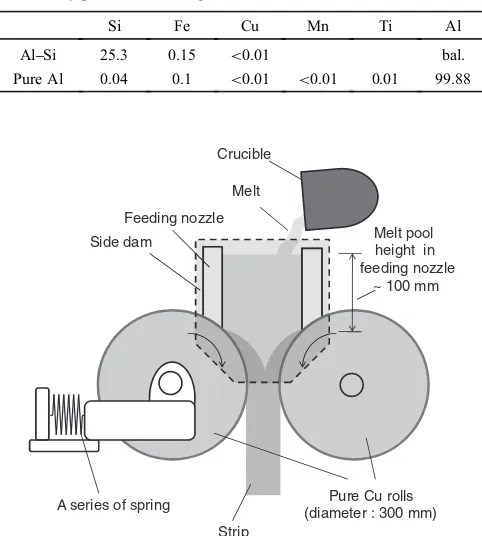
Figure 1 shows a schematic illustration of the laboratory-scale vertical-type twin-roll caster used in the present study. In the caster, a large feeding nozzle, which is not available for the conventional vertical-type caster, was used to maintain a high melt pool level during the strip casting. The feeding nozzle consisting of steel plates covered with a heat-insulating material was mounted on the rolls so that the bottom-end of the nozzle contacted directly with the roll surface. A pair of side dams made of steel plates covered with replaceable heat insulating sheets was set on the side-edge of the nozzle and the casting roll. The caster was equipped with a pair of pure copper rolls (made of tough-pitch copper) with 300 mm in diameter and 100 mm in width. No lubricant was applied on the roll surface. The casting rolls were internally cooled with running water during the casting. One of the rolls
was loosely fixed by being supported by a series of springs to control the roll separating force, while the other one was
fixedfirmly. The roll separating force was controlled by using six springs connecting in parallel. Each spring had a free length of 150 mm. The initial roll separating force was obtained by setting their length to the pre-determined values. For example, for a single spring, the spring constant is 0.47 kN/mm. The initial roll separating force of 0.47 kN was obtained by spring length reduction of 1 mm from the initial length. Since six springs supported the roll, total force was 2.82 kN. The value obtained in this way was regarded as initial roll separating force. During strip casting, the pre-set force was applied on the strip near the roll nip by enlarging the roll gap. In the present study, the initial roll separating force was controlled in a range from 3 to 60 kN.
The molten metal of 2.5 kg in the crucible was poured into the nozzle from the fixed roll side toward the movable roll side when the superheat of the melt reached approximately 5°C. The pouring was conducted manually as fast as possible, but very carefully so that the maximum height of the melt pool in the nozzle was kept at 100 mm. Roll rotating speed was 60 m/min. The initial roll gap was 1 mm. This procedure allowed to obtain a 34 m long and 100 mm wide strip.
2.3 Microstructure observations
[image:2.595.306.547.89.357.2]The strip surface was observed by using a scanning electron microscope (SEM). The solidification structure observation was conducted on the longitudinal cross section of the mid-width of the cast strip. For cross-sectional microstructure observation, the longitudinally sectioned samples were mounted in an epoxy resin and polished. The polished cross-section was etched with 2%HF and distilled
Table 1 Chemical compositions (mass%) of Al25 mass% Si and com-mercially pure aluminum ingots.
Si Fe Cu Mn Ti Al
AlSi 25.3 0.15 <0.01 bal.
Pure Al 0.04 0.1 <0.01 <0.01 0.01 99.88
Melt Crucible
Feeding nozzle
A series of spring Pure Cu rolls
(diameter : 300 mm) Side dam
Strip
Melt pool height in feeding nozzle
~ 100 mm
H2O solution, and observed using an optical microscope
(OM). As-polished cross-sections were also anodized at 40 V voltages in a 3.3% HBF4and distilled H2O solution to
reveal the grain structure. Compositional change by inverse segregation at the surface region of the cast strip was examined by using a scanning electron microscopy with energy-dispersive X-ray spectroscopy (SEM-EDS).
3. Results
3.1 Characterization of the cast strip
3.1.1 Change in strip thickness along the casting direction
A strip about 3 m long with 100 mm in width was fabricated under the initial roll separating force of 20 kN. Figure 2 shows the change in strip thickness along the strip length. Thex-axis of thefigure indicates the length from the strip head. The origin of thex-axis corresponds to the leading edge of the strip. The thickness of the cast strip was measured for two positions: mid-central line of the strip and 20 mm apart from the central line. No thickness difference was observed in the width direction. The thickness change along the strip length can be divided into three zones. In the zone I in Fig. 2, the strip thickness increased continuously. This is the stage when the molten metal poured from the crucible is
filling the nozzle and a thin solid skin starts growing on the roll surfaces. The zone I is followed by zone II in Fig. 2, where the strip thickness was almost constant. The constant thickness in the zone II is attributed to the constant melt height level in the nozzle. Gradually running out of the melt, the melt pool level in the nozzle decreases and thus the strip thickness decreases continuously. This stage corresponds to the zone III in Fig. 2.
3.1.2 Macro- and microscopic appearance of the strip surface
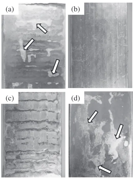
Figure 3 shows the appearance of strip surface of each zone shown in Fig. 2. At the initial part (zone I in Fig. 2), where the strip thickness gradually increases, discontinuous
“un-shiny” regions were observed on the strip surface, as indicated by arrows in the Fig. 3(a). In addition, periodical oscillation patterns, which are formed normal to the casting direction, were observed on the surface. In the zone II, where the strip thickness is constant, the surface is flat and shiny and un-shiny region and oscillation patterns were not
observed, as shown in Fig. 3(b). In the zone III, where the strip thickness continuously decreases, two distinct features are exhibited. In the zone III-(C), the periodical ripple marks were clearly observed on the strip surface (Fig. 3(c)). Such a ripple mark is frequently observed on the strip surface produced by the horizontal-type twin-roll casting.19) In the zone III-(D), no ripple marks were observed, but the un-shiny region appeared again on the strip surface, as indicated by arrows in Fig. 3(d).
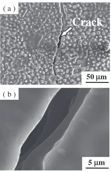
Figure 4 shows the SEM-image of the strip surface. Fine dendrite cells were clearly observed on the shiny strip surface. These polygonal dendrite cells are probably the chilled crystals on the roll surface. As shown in the Fig. 3, the strip surface in the zone I and III consists of two regions: relatively shiny, smooth region and un-shiny region. Figures 4(c) and 4(d) display the surface morphology of the relatively shiny and smooth region. In this region, a large amount of fine eutectic Si particles and plate-like AlFeSi based intermetallic compound particles are dispersed on the surface. Figures 4(e) and 4(f ) exhibit the microstructure of the “un-shiny region”, as indicated by the arrows in the Fig. 3. In this region, the strip surface is not flat, but, as shown in the Fig. 4(f ), the surface is covered with many clumps. In addition, cracks were observed in this region, as shown in Fig. 5. The micrograph with high magnification in Fig. 5(b) reveals that the surface of the crack is a smooth dendrite cell surface.
3.1.3 Grain structure
Figure 6 shows the grain structure for each part of the cast strip shown in Fig. 2. It is noted that the left-hand side of
0 0 1 2 3 4 5
Center
20 mm from center
Strip length,
l
/ m
Strip thickness,
t
/ mm
(A) (B) (C) (D)
Leading edge of strip
1 2 3
Fig. 2 Change in the strip thickness along the strip length. (The result was divided into three zone, I, II and III depending on the macroscopic trend of the thickness change).
(a)
(b)
(c)
(d)
[image:3.595.312.541.67.374.2] [image:3.595.74.266.71.199.2]each picture corresponds to the strip surface of the movable roll side in Fig. 1. The microstructure of the very initial part (Fig. 6(a)) is characterized by columnar grains grown from both roll surfaces, and equiaxed grains in the mid-thickness region. In the zone I-(B), in which the strip thickness increases, well-developed columnar grains are observed in the inner region of the movable roll side (Fig. 6(b)). In contrast, equiaxed grains are observed in the fixed roll side (Fig. 6(b)). In the zone II, with a constant strip thickness, the microstructure exhibits small columnar grains in chill zone at the strip surface, equiaxed grains in the sub-surface region and a large amount of fine globular grains in the mid-thickness region (Fig. 6(c)). The globular grains form a band structure which is clearly distinguishable from the outer shells consisting of the fine columnar and equiaxed grains. In thefinal part of the strip (zone III), the microstructure is similar to that of the zone II, but there is no fine columnar grains in the surface region, i.e., no chill zone formed at the strip surface (Fig. 6(d)).
A large-scale internal cracking formed continuously is observed in the mid-thickness region, as indicated by an arrow in the Fig. 6(c). The cracking always appears in the central band region consisting offine globular grains, mostly at a boundary between the central band and the outer shell. 3.1.4 Central band thickness and internal cracking
A change of the strip thickness and the central band thickness are shown in Fig. 7. The central band thickness was obtained as follows. An area of the central band region was measured for the pre-determined length in the longitudinal cross section, and the area was divided by the length to obtain the band thickness. Six parts were measured to obtain an averaged value. In the constant strip thickness zone, the central band thickness showed nearly constant value, about 400500 µm. In the final part of the strip, the central band becomes large, about 700 µm in thickness, which is about half of the strip thickness.
A zone, in which internal cracking is observed, is also indicated in Fig. 7. The area roughly corresponds to the zone II. In contrast, no crack was observed at thefinal part of the strip.
( a )
( c )
( b )
( e )
( d )
( f )
20 µm 20 µm 20 µm
( )
( )
5 µm
5 µm 5 µm
Fig. 4 SEM-image of strip surface. Microstructure of (a), (b) the constant thickness zone (zone II in Fig. 2), (c), (d) relatively shiny and smooth surface region in zone I and III, (e), (f ) the“un-shiny region”in zone I and III in Fig. 2; (i) and (ii) indicate Si and AlSiFe intermetallic compound particles, respectively.
( b )
( a )
Crack
5
µ
m
50
µ
m
Fig. 5 Microstructure of the“un-shiny”region revealing the“hot tearing”: (a) low-magnification, (b) magnified microstructure of the“hot tearing” region in (a).
1 mm
Internal cracking
(a) (b)
(c) (d)
[image:4.595.311.541.69.239.2] [image:4.595.49.291.70.340.2] [image:4.595.63.277.422.753.2]3.1.5 Inverse segregation
Figure 8 shows OM-image of the cross-section near the surface and the results of SEM-EDS compositional mapping for Al and Si elements in a part of these areas. For the strip surface in zone II, no segregation was detected. On the other hand, for the strip surface in zone I and III, a thin layer rich in Si was detected by EDS composition analysis.
3.2 Influence of the roll separating force
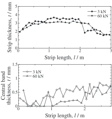
[image:5.595.331.523.68.273.2]In order to examine the effect of roll separating force on the internal cracking, Al2 mass% Si alloy strips were also cast under two different initial roll separating forces of 3 and 60 kN, which are smaller and higher than 20 kN, respectively. Figure 9 shows the comparison of the strip thickness and the central band thickness under the two conditions. In the zone II showing constant strip thickness, about 0.5 mm thickness reduction took place by the increase of the roll separating force from 3 to 60 kN, while no prominent change in thickness was observed in zone I and III. It is shown that the amount of strip thickness reduction corresponds to that of the central band region. Figure 10 shows the microstructural change of the central regions of the cast strips corresponding
to the increase of the initial roll separating force from 3 to 60 kN. For 3 kN, the thick central band consists of fine globular grains, as shown in the Fig. 10(a). A large volume of porosity was also observed. In this case, the large-scale
0 1 2 3
0 1 2 3 4 5
Strip length, l / m
Thickness,
d
/ mm
Strip thickness Central band thickness
Internal cracking zone
Fig. 7 Change in the strip thickness and the central band thickness along the casting direction; Initial roll separating force: 20 kN.
Zone Zone and
OM image
EDS composition map
Al
Si
50 µm 50 µm
Fig. 8 OM-image in the surface region and the result of EDS composition mapping for Al and Si elements; I, II and III indicate each zone in Fig. 2.
0 1 2
0 0.5 1 1.5
Strip length, l / m
Central band
thickness,
t
/ mm
3 kN 60 kN
0 1 2 3
0 1 2 3 4 5
Strip length, l / m
Strip thickness,
t
/ mm 3 kN 60 kN
Fig. 9 Changes in the strip thickness and the central band thickness along the casting direction for two initial roll separating force of 3 and 60 kN.
: Central band region
250
µ
m
(a)
(b)
[image:5.595.74.267.73.160.2] [image:5.595.48.290.209.474.2] [image:5.595.319.534.317.690.2]internal cracking, which appeared under the condition of 20 kN, did not occur. On the other hand, in the case of 60 kN, a semi-continuous thin band structure was observed in the mid-thickness region, as shown in Fig. 10(b). No internal cracking was observed in this case, either.
4. Discussion
4.1 The effect of melt pool level on the casting defects and the solidification structure
4.1.1 The role of the melt pool level in strip fabrication The melt feeding system, which controls the fluid flow of the molten metal, is very critical for twin-roll casting operation because it affects the strip quality: such as surface defects, strip thickness deviation and solidification structure, etc.4,2024) The stabilized melt supply is closely related to a stable and uniform heat transfer condition between the growing solid shell and the moving substrate (i.e., the rotating roll surface). In order to achieve a stable feeding condition, several trials have been made so far. Among them, modifying the casting rolls arrangement (roughly divided into three types: vertical, horizontal and inclined-type) and optimization of the design and the position of the feeding nozzle4)were the most important trials. Hwang et al. performed both experimental and simulated works21)using an inclined twin-roll caster. They reported that the combined effect of melt pool level and nozzle position brought about the change in recirculation pattern of the melt, which directly affect fl uc-tuation of the meniscus where solid shell, melt and air contact. A high melt pool level resulted in a relatively stable flow condition, yet, a violent fluctuation at the meniscus caused the formation of dross-trapped and wrinkled strip surface as well as strip thickness deviation. The computational results by Bae et al.22) indicated that the flow pattern affects the
cooling rates of the solidifying shells on the roll surface. They also mentioned that a high level of the melt pool is desired for the stable growth of shells on the rotating roll surface.
Keeping a stable contact condition between the solidifying shell and the roll surface is very important to fabricate the sound strip with no surface defect and thickness deviation. In order to achieve this by the present high-speed twin-roll casting method, a hydrostatic pressure is applied on the solidifying shell traveling on the roll surface using a melt head in the nozzle. The hydrostatic pressure is indispensable to compensate for the thermal contraction and shrinkage of the solidifying shell, which can lead to air gap formation between the solidifying shell and the roll surface. In the present study, the melt feeding to the nozzle was conducted manually by tilting the crucible. Therefore, precise control of the melt flow is difficult in the beginning of feeding. However, once the feeding nozzle isfilled with the melt and the high melt pool level is attained, the turbulent flow induced by the successive pouring does not affect the solidification condition on the roll surface. The large hydrostatic pressure induced by high melt pool level in the nozzle also improves the contact condition between the solidifying shell and the roll surface. The formation of well-developed chill zone (Fig. 8) reflects the improved contact condition at the initial stage of the solidification where the solid shell began to form on the roll surface. The good
surface quality and constant strip thickness in the zone II in Fig. 3 are considered to result from this effect.
In the present study, a single shot of the melt from the cruciblefilled the nozzle and formed a single strip. Therefore, the change in melt pool height directly affected the strip thickness. In Fig. 2(a), the strip thickness increases with increase of the melt pool level at the initial stage, and then reaches the relatively constant thickness under the constant melt pool level. At thefinal stage, the thickness decreases as the melt pool level decreases. The change in the melt pool level causes the change in hydrostatic pressure, and affects heat transfer between the solidifying shell and the roll surface. Therefore, these suggest that constructing high melt pool level using the present nozzle type is effective to improve the contact condition, which can control a formation of strip thickness, solidification structure and surface defects. 4.1.2 The formation of the ripple mark and the
“un-shiny region”on the strip surface
The surface defect is one of the most troublesome problems in the twin-roll casting because the strip surface is not removed by machining and is supplied to successive hot rolling or cold rolling. For the surface of the strip, which was fabricated under the relatively low melt pool level condition, two kinds of macroscopic defects were observed: ripple mark and“un-shiny”region. The ripple mark, shown in the zone III-(C) in Fig. 3, is a typical defect in horizontal-type twin-roll casting process.19) This can be formed when
unstable solidification takes place in the section where a thin solid shell starts to grow on the roll surface. At this stage, if the hydrostatic pressure is scarce around the thin shell, the detachment of the shell from the roll surface can take place due to the force of the solidification shrinkage. This allows the following melt to permeate to the gap created, resulting in an overlaid structure. This step occurs continuously, and consequently ripple marks are formed periodically on the cast strip (zone III-(C) in Fig. 3).
The “un-shiny”region, observed in Fig. 3, also seems to be related to poor contact condition. A large number of clumps result in uneven surface condition in the “un-shiny” region, as shown in Figs. 4(e) and 4(f ). Since the distance between the clumps roughly corresponds to the dendrite arm spacing in the sub-surface region of zone I and III, as displayed in the upper-right side in Fig. 8, the clump formation is considered to result from inter-dendritic leakage of liquid during the strip casting. Furthermore, the well-projected clumps on the surface indicate poor contact condition of this region until the strip passed through the roll nip. Therefore, due to locally degraded heat extraction condition in this region, the liquid at the dendrite cell boundary is more likely to be preserved, even near the surface region. As a result, surface cracking induced by the “hot tearing”can occur in the un-shiny region, as shown in Fig. 5. 4.1.3 Formation of inverse segregation
direction to the shell growth direction.28)A liquidflow that is
driven by the pressure drop due to the air gap formation on the casting surface is also an important phenomenon of the inverse segregation.29) Forbord et al.27) used AlStrip-model
to reproduce the condition for the inverse segregation in horizontal-type twin-roll casting. In their model, it was shown that the low pressure zone was constructed near the surface region of solidifying shell, and the zone corresponded to the area of the inverse segregation. In the present casting, in the same context, due to the solidification shrinkage and the formation of the large air gap (poor contact condition), the liquid at the inter-dendritic region can be exuded into the surface region. Consequently, an undesired layer with a high solute content appeared on the strip surface.
4.1.4 Formation of grain structure
Change in solidification structure along the casting direction (Fig. 6) indicates that the structure formation is also affected by the melt pool level. Basically, roll temper-ature increase is expected to some extent in one revolution of the roll. Actually, we produced a 15 m long strip using the present caster without thickness change along the casting direction in the 12 m long stage II region. Therefore, the temperature increased after one revolution is considered to be maintained somewhat constant even though it can show a slight increase if the casting proceeds for much longer time. The diameter of the roll in the present study was 300 mm, and so circumferential length was about 1 m. Therefore, the initial part of the strip, at least 1 m long, should be regarded as the unstable part of the strip. However, this unstable initial part provided us important information concerning the solid-ification manner of the cast strip. Therefore, we focused on this stage.
In the very initial part of the strip (Fig. 6(a)), a steep thermal gradient, originating from the low roll surface temperature, promotes the growth of the columnar grains on the roll surface. As the casting proceeds, this zone is followed by the transition zone, in which columnar and equiaxed grains co-exist, as shown in Fig. 6(b). Since the part in the zone I-(B) was fabricated during the stage when the poured melt did not fill the nozzle completely yet, the resultant solidification structure is related to the unstable melt pool condition. In general solidification, it is known that solidification structure is mainly determined by the ratio of thermal gradient, G and growth rate, R, (G/R).30) In the
present casting, it is possible that the unstable contact condition between the growing shell and the roll surface
fluctuatesG/Rvalue, and thefluctuation triggers a structure transition from columnar to equiaxed grain.31) There are
several possibilities to produce the unstable contact con-dition. The solidification of the transition zone takes place before constructing the stable melt pool level in the nozzle. As the strip thickness increases continuously, an overall contraction of the shell can lead to the large air gap formation. Another possibility is related to the turbulent
flow induced by the melt pouring. In the transition zone, local pressure change, induced by the turbulentfluidflow, can be generated. As a result, the contact condition can befluctuated locally. Since the melt pouring is conducted from the fixed roll side toward the movable roll side in the present study, the turbulence of the melt flow seemed to affect the solidifying
condition on the movable roll side. At the constant thickness zone (Fig. 6(c)), the constant melt pool level in the nozzle facilitated a stable contact between the solidifying shell and the roll surface, resulting in quite homogeneous grain structure. At this stage, after one revolution, the roll temperature seemed to increase to some extent. An effect of the increased roll temperature and the low melt superheat (about 5°C in this study) is considered to decrease the thermal gradient, G, at the growth front and promote the formation of the equiaxed grains,30)as shown in Fig. 6(c).
4.2 Formation mechanism of internal cracking
A large-scale internal cracking is a serious problem in high-speed twin-roll cast aluminum alloy strips.11) It was
already shown in the previous study14) that a thick band
structure consisting of fine globular grains formed in the alloys with wide freezing temperature range, and the internal cracking always occurred in the central band region. The fractography14)found that the crack surface was covered with
smooth round tips of dendrite branches and globular grains. This indicates that the internal cracking is not a post-solidification fracture, but results from the continuously connected shrinkage cavities.
In Fig. 7, the internal cracking is observed in the zone II. In contrast, no crack was observed at the final part of the strip, in spite of the thick central band. It is assumed that the final part of the strip is formed under a very small roll separating force due to a thin strip thickness (i.e., small enlargement of the roll gap near the roll nip). At thefinal part of strip in Fig. 9, no prominent change in the central band thickness also supports this. These finding suggest that the applied roll separating force is a controlling factor of the internal cracking.
In addition to this, according to the results described in 3.2, following two conditions are considered to cause the internal cracking: (1) formation of a thick central band consisting of the fine globular grains and (2) applying a certain extent of external stress (i.e., the roll separating force) to the central band region in the semi-solid state.
The amount of residual liquid in the central band region is greatly influenced by the roll separating force.11)As the roll
separating force increases, the cooling rates near the roll nip increases due to improved contact condition between the roll surface and the solidifying shell.11)In addition, the liquid
in the central band region can be reduced through“squeezing out”, by applying a high roll separating force.11)
Conse-quently, the amount of residual liquid decreased with the increase of the roll separating force. This explains why either a thin or no central band are formed, and is also the reason why no internal cracking in the strip at 60 kN exists (Fig. 10(b)).
With respect to the “shear localization”, a similar phe-nomenon can be found in a simple compression experiment. Tzimas and Zavaliangos32) performed the compression test
of semi-solid Al4 mass% Cu alloy consisting of equiaxed grains. They reported that the shear localization was observed at a high solid fraction, especially above 0.85 and the shear localized zone appeared as a porosity band in the compressed specimens. Such shear localization occurs to accommodate the compressive force introduced when the overall grain rearrangement is restricted by the increase of grain boundary cohesion at a high solid fraction. In this case, the specimen was easily split into two parts even under a small force in tension when the crosshead was reversed after the end of the compression. The fracture surface exhibited smooth grain surfaces, which indicates that the grain boundaries were surrounded by liquid.
In a similar context, the roll separating force is considered to cause the shear localization in the central band region in semi-solid state. Once the shear localization takes place, since the external stress disturbs the creation of a bridge between grains in the shear localized zone, the rapid shearing facilitates the formation of continuous liquid film at this region. If the liquidfilm was maintained until the strip passes through the roll nip, it would eventually appear as the internal cracking.
5. Conclusions
A strip of Al2 mass%Si alloy, which has a wide freezing temperature range, was fabricated using a high-speed twin-roll caster. In this study, a large feeding nozzle was used to obtain a high melt pool level during the strip casting. Formation of solidification structure and several casting defects such as inverse segregation and internal cracking were studied, and the following conclusions were drawn.
(1) Un-stable contact condition between the solidifying shell and the roll surface was considered to result in several kinds of surface defects such as the ripple mark,“un-shiny”region and the compositional inverse segregation as well as in-homogeneous grain structure. As the melt pool level in the nozzle increased, the strip thickness increased by improved contact condition between the solidifying shell and the roll surface and the overall contact condition became stable. By constructing and keeping the high melt pool level in the feeding nozzle, the formation of the surface defects was prevented effectively.
(2) A large-scale internal cracking was observed in the central band region consisting of fine globular grains. The cracking was assumed to relate with the residual liquid in the central band and the roll separating force. It was considered that the roll separating force caused the shear localization in the central band region and promoted a formation of continuous liquid film in the
shear localized region, and consequently, the connected shrinkage cavity in the liquid film resulted in the continuous internal cracking when the strip went through the roll nip.
REFERENCES
1) H. Bessemer: U. S. Patent No. 49, 053, July 25 (1865). 2) N. Zapuskalov:ISIJ Int.43(2003) 11151127.
3) R. Cook, P. G. Grocock, P. M. Thomas, D. V. Edmonds and J. D. Hunt: J. Mater. Process. Technol.55(1995) 7684.
4) B. Q. Li:JOM47-5 (1995) 2933.
5) R. Wechsler:Scand. J. Metall.32(2003) 5863. 6) K. Schwerdtfeger:ISIJ Int.38(1998) 852861.
7) M. Yun, S. Lokyer and J. D. Hunt:Mater. Sci. Eng. A280(2000) 116 123.
8) T. Haga and S. Suzuki: J. Mater. Process. Technol.143144(2003) 895900.
9) T. Haga, K. Takahashi, M. Ikawa and H. Watari: J. Mater. Process. Technol.140(2003) 610615.
10) K. Suzuki, S. Kumai, Y. Saito, A. Sato and T. Haga:Mater. Trans.45 (2004) 403406.
11) M. S. Kim, Y. Arai, Y. Hori and S. Kumai:Mater. Trans.51(2010) 18541860.
12) M. S. Kim and S. Kumai: Proc. 12th Int. Conf. on Aluminum Alloys, September 59, Yokohama, Japan, (2010) pp. 693697.
13) K. Suzuki, S. Kumai, K. Tokuda, T. Miyazaki, A. Ishihara, Y. Nagata and T. Haga:Mater. Sci. Forum519521(2006) 18211826. 14) M. S. Kim and S. Kumai:Mater. Trans.52(2011) 856861. 15) D. Shimosaka, S. Kumai, F. Casarotto and S. Watanabe:Mater. Trans.
52(2011) 920927.
16) O. Umezawa, M. Nakamoto, Y. Osawa, K. Suzuki and S. Kumai: Mater. Trans.46(2005) 26092615.
17) K. Suzuki, S. Kumai, Y. Saito and T. Haga:Mater. Trans.46(2005) 26022608.
18) T. Haga, M. Ikawa, H. Watari, K. Suzuki and S. Kumai:Mater. Trans. 46(2005) 25962601.
19) H. Esaki, Y. Watanabe, K. Ueda, H. Uto and K. Shibue:J. Japan Inst. Light Met.56(2006) 266270.
20) N. Zapuskalov and M. Vereschagin:ISIJ Int.38(1998) 11071113. 21) J. D. Hwang, H. J. Lin, J. S. C. Jang, W. S. Hwang and C. T. Hu:ISIJ
Int.36(1996) 690699.
22) J. W. Bae, C. G. Kang and S. B. Kang:J. Mater. Process. Technol.191 (2007) 251255.
23) K. Shibuya and M. Ozawa:ISIJ Int.31(1991) 661668.
24) H. Yasunaka, K. Taniguchi, M. Kokita and T. Inoue:ISIJ Int.35(1995) 784789.
25) Ch. Gras, M. Meredith and J. D. Hunt:J. Mater. Process. Technol.167 (2005) 6272.
26) D. Monaghan, M. B. Henderson, J. D. Hunt and D. V. Edmonds:Mater. Sci. Eng. A173(1993) 251254.
27) B. Forbord, B. Andersson, F. Ingvaldsen, O. Austevik, J. A. Horst and I. Skauvik:Mater. Sci. Eng. A415(2006) 1220.
28) M. C. Flemings:Solidification Processing, (McGrow-Hill, USA, 1974) pp. 234262.
29) E. Haug, A. Mo and H. J. Thevik:Int. J. Heat Mass Transfer38(1995) 15531563.
30) W. Kurz and D. J. Fisher:Fundamentals of Solidification, (Trans Tech Publications Ltd., Switzerland, 1998) pp. 6974.
31) C. A. Siqueira, N. Cheung and A. Garcia:Metall. Mater. Trans. A33 (2002) 21072118.