Effect of Dissolved Oxygen Content on Pin-on-Disc Wear Behavior of Biomedical
Co-Cr-Mo Alloys in a Like-on-Like Configuration in Distilled Water
Kazushige Kumagai
1;*, Naoyuki Nomura
2and Akihiko Chiba
31
Center for Regional Collaboration in Research and Education, Iwate University, Morioka 020-8551, Japan
2Department of Welfare Engineering, Faculty of Engineering, Iwate University, Morioka 020-8551, Japan 3Institute for Materials Research, Tohoku University, Sendai 980-8557, Japan
The wear behavior of a forged Co-29Cr-6Mo alloy without any Ni and C added has been investigated by using a tribosystem consisting of a pin-on-disc type wear testing machine in distilled water containing different dissolved oxygen content. Dissolved oxygen content in the distilled water was controlled by aerating with oxygen or by deaerating with argon. Wear volume in the distilled water containing high oxygen content is approximately two times larger than in that containing low oxygen content. Accordingly, it is deduced that the overall wear volume is significantly affected by the dissolved oxygen content in the distilled water surrounding the tribosystem. Although abrasive wear, caused by wear debris, is operative as a wear mechanism in the present tribosystem irrespective of oxygen content, the transfer of the wear debris to sliding surfaces, as well as the aggregation of the wear debris on the sliding surfaces, is more prone to occur during the wear process with the lower oxygen content. Therefore, in the present tribosystem with the lower oxygen content, since the transfer of the wear debris to the disc or the pin readily occurs, the generation of the wear debris does not directly contribute to the wear volume, leading to the apparently lower wear volume in the tribosystem with lower oxygen content than in that with higher oxygen content; the transfer of the wear debris is not counted as wear loss because the wear volume is estimated based on the loss in disc and pin weight that occurs during the wear test.
[doi:10.2320/matertrans.MRA2007601]
(Received January 24, 2007; Accepted March 19, 2007; Published May 25, 2007)
Keywords: biomaterial, medical implants, cobalt-chromium-molybdenum alloy, wear, wear behavior, wear mechanism, pin-on-disc, metal-on-metal, adhesion, oxidation, three-body abrasion
1. Introduction
Total hip and knee arthroplastic surgery was a major medical advance of the 20th century. In total prosthesis, the contact is made between the two components of an artificial implant: an acetabular cup and a femoral head. The materials used for this medical application must possess satisfactory mechanical properties such as wear, fatigue, and corrosion resistance, and must not pose a risk to biocompatibility. Cobalt chromium molybdenum (Co-Cr-Mo) alloys have been used for total hip and knee prostheses, mainly because of
their excellent corrosion and wear resistance.1–3)Co-Cr-Mo
alloys have been used for Metal-on-Polyethylene (MOP) total hip arthroplasty bearings. Conventional cast Co-Cr-Mo alloys are allowed to be less than 1 mass% of Ni concen-tration. However, since the human body’s allergy to Ni has
been studied recently,4,5)the development of Ni-free
Co-Cr-Mo is strongly required. C concentration in Co-Cr-Co-Cr-Mo alloys
is also allowed to be less than 0.35 mass%.6) The
conven-tional Co-Cr-Mo-C alloys have been expected to exhibit excellent wear resistance owing to the precipitation of
carbide.7) However, the wear debris of MOP articulated
prostheses, mostly generated from polyethylene particles by wearing due to abrasion by carbides precipitated in the Co-Cr-Mo alloy, has been correlated with particle-induced
osteolysis and implant loosening.8,9) As an alternative to
MOP articulated prosthesis, Metal-on-Metal (MOM) articu-lated prostheses are increasingly gaining more
accept-ance,10–13) since the wear rate of MOM (3.0mm/year) is
lower than that of MOP (100–200mm/year).14,15)
The forged Co-Cr-Mo alloy without any Ni and C added has a fine grained microstructure and has higher mechanical
properties than conventional Co-Cr-Mo alloys.16) Because
the forged Co-Cr-Mo alloy possesses low stacking fault
energy,17)the forged Co-Cr-Mo alloy has a metastable face
centered cubic (fcc) phase. The metastable fcc phase easily undergoes strain-induced martensite transformation to stable hexagonal closed packed (hcp) phase. In addition, the forged Co-Cr-Mo alloy has been reported to possess excellent wear
resistance.18,19)According to Chibaet al., the forged
Co-Cr-Mo alloy, with no carbide and a refined grain size, which is more prone to strain-induced martensitic transformation, would exhibit excellent like-on-like wear resistance, mostly against surface fatigue wear, compared to the
carbide-hardened cast Co-Cr-Mo alloy.19) Besides the
above-men-tioned mechanical properties, since oxide film is spontane-ously generated on the surface of the forged Co-Cr-Mo alloy, the surface oxide strongly correlates to wear properties not
only electrochemically but also mechanically.20–23) In order
to develop a Co-Cr-Mo alloy with high wear resistance, it is necessary to clarify the effect of the surface oxide on wear properties.
Thus, the aim of the present study is, firstly, to examine the effect of the dissolved oxygen content on the wear behavior of the forged Co-Cr-Mo alloy without any Ni and C added in distilled water that contains different oxygen content. Secondly, based on experimental findings, we will discuss the effect that oxide films spontaneously generated on the sliding surfaces, including wear debris, have on the resulting wear, especially in the pin-on-disc wear testing apparatus.
2. Materials and Methods
2.1 Sample preparation
The nominal composition prepared in this study is Co-29 mass%Cr-6 mass%Mo. The 5-kg alloy ingot was prepared
by vacuum induction melting. Prior to forging the ingot, annealing treatment was conducted at 1523 K for 43.2 ks for homogenization, and then cooled in water. The ingot was forged at temperatures higher than 1273 K. The total reduction in area of the forged ingot was approximately 82%. The chemical composition of the forged alloy is shown in Table 1. The detected Ni is attributed to impurities, and the detected C is unreactive Carbon for deoxidation.
2.2 Microstructure characterization
The grain size of the forged alloy was determined metallographically with an optical microscope (OM). A specimen for the observation was polished with #6000 emery paper and then electrically polished at a voltage of 6 V in a solution of 90 parts methanol plus 10 parts sulfuric acid at room temperature.
Crystal structure identification of the forged alloy was performed with an X-ray diffractmeter (XRD) using
mono-chromated Cu K radiation over 30280. X-ray
voltage, current, and scan rate were 40 kV, 30 mA, and 1.000 deg/min, respectively.
2.3 Wear test
The disc and pin specimens for the wear test were cut from the forged ingot by an electro-discharge machine (EDM). The disc specimens were 30 mm in diameter and 5 mm in thickness. The pin specimens were 6 mm in diameter and 20 mm in length. One of the edges of the contact side was cut hemispheric at a radius of 2.4 mm.
The surface of specimens was polished up to a surface
roughness (Ra) of less than 0.05mm. Wear tests were
conducted using a conventional pin-on-disc apparatus (RHESCA, FRP-2000). Figure 1 shows a schematic drawing of the pin-on-disc wear test. The deadweight of the applied load was 9.8 N. The sliding distance was 12.1 km. The sliding speed was 20 mm/s. The temperature of the distilled water was kept at 310 K during the wear test. The dissolved oxygen content in the distilled water was controlled by aerating with oxygen and by deaerating with argon during the wear test. Oxygen and argon gasses were bubbled at 100 ml/min. The overall wear volume obtained was the summation of the wear volume of the pin and the disc and was calculated by using equation (1) as follows:
V ¼Mloss
ð1Þ
WhereMloss is the summation of the weight loss of the pin
and disc specimen and is the density of the forged alloy.
Hereafter, the wear test measurements under conditions with aerating with oxygen and with deaerating with argon are designated ‘‘oxygen bubbling’’ and ‘‘argon bubbling’’, re-spectively. The oxygen content with argon bubbling and oxygen bubbling was about 0.90 mg O/l and above 14.0 mg O/l, respectively.
Wear scars were also analyzed by means of a scanning electron microscope (SEM) and a confocal 3D profilometer.
3. Results
3.1 Characterization of the forged alloy
Figure 2 shows the OM micrograph of the forged alloy used in the wear tests. As can be seen, the microstructure with the equiaxed grains containing striations in their interior,
shows a mean grain diameter of approximately 14mm, while
second phases such as carbides and sigma phases are not observed.
Figure 3 shows the XRD profile of the forged alloy. As seen in the figure, it is found that the forged alloy has two phases consisting of fcc and hcp crystal structures. Since the forged alloy underwent water quenching just after heat treatment, the striations observed in the OM micrograph, shown in Fig. 2, are associated with the athermal martensitic phase with hcp crystal structure. In addition, the ratio of the
peak intensity ofð200Þfccto that ofð111Þfccof the forged alloy
is calculated to be 0.36, while that of the theoretical counterpart of the Co-Cr-Mo alloy consisting of complete equiaxed grains without texture is 0.47, suggesting that the
forged alloy used in the wear tests possesses a weakð111Þfcc
oriented structure normal to the polished surface of the disc.
[image:2.595.332.524.73.217.2]3.2 Wear tests
Figure 4 shows (a) the overall wear volume and (b) the friction coefficient of the forged alloy. As can be seen in Table 1 Chemical composition of the forged alloy (mass%).
Co Cr Mo Ni C Si O N
Bal. 28.42 5.92 <0:02 0.016 0.01 0.0032 0.0006
Disc
Thermocouple
Heating
Load
Gas
Pin
Fluid
Fig. 1 Schematic drawing of pin-on-disc wear test.
20
µ
m
[image:2.595.45.293.86.112.2] [image:2.595.333.518.262.396.2]Fig. 4(a), surprisingly, the wear volume with oxygen bub-bling is approximately two times that with argon bubbub-bling in spite of the fact that the same tribosystem was used, except for the dissolved oxygen content in the distilled water. Accordingly, it is inferred that the overall wear volume is highly dependent on bubbling methods with or without oxygen, meaning that the dissolved oxygen content in the distilled water surrounding the tribosystem has a significant effect on the wear volume.
In Fig. 4(b), the friction coefficients range from 0.5 to 0.6 under both bubbling conditions, in which no significant difference is found.
3.3 Observation of wear scars
Figure 5 shows SEM micrographs of the wear scar of the disc with oxygen bubbling: (a) wear scar, (b) magnified view
of the wear scar and (c) backscattered electron image of the magnified view. The arrows in the figures indicate the sliding direction of the pin. The various scratches, parallel to the sliding direction of the pin, are observed in the wear scar. The scratches are characteristic of abrasive wear. Thus, we find that the three-body wear, associated with wear debris, is operative as a wear mechanism in the present tribosystem. Furthermore, the band-like contrast between the scratches, colored light grey, is thought to be wear debris adhering to the wear surface during the wear process. In the case of oxygen bubbling, the resultant roughness (Ra) on the worn
surface after the wear test was found to be 0.308mm.
Intensity (A.U.)
30° 40° 50° 60° 70° 80°
(0002)
hcp
(1010)
hcp
(1011)
hcp
(111)
fcc
(200)
fcc
(1012)
hcp
(220)
fcc
Fig. 3 XRD profile of the forged alloy.
0.2 0.3 0.4 0.5 0.6 0.7 0.8 0 0.1 0.2 0.3 0.4 0.5 0.6 0.7 0.8
O2Bubbling Ar Bubbling
Overall wear volume,
V
/ mm
3
Friction coefficient,
µ
O2Bubbling Ar Bubbling
(a)
(b)
Fig. 4 Overall wear volume (a) and friction coefficient (b) of the forged alloy.
50
µ
m
10
µ
m
BSE
10
µ
m
SE
(c)
(b)
(a)
Ra: 0.308
±
0.038
µ
m
[image:3.595.69.267.72.201.2] [image:3.595.321.531.73.585.2] [image:3.595.65.275.224.541.2]Figure 6 shows the SEM micrograph of the wear scar of the pin with oxygen bubbling. In addition to abrasive scratches, similar to those of the wear scar of the disc (Fig. 5), wear debris appearing in dark grey contrast, concomitant with cracks running along a direction
approx-imately 45from that of the lines of the scratches, is observed
on the worn surface of the pin. As pointed out by Chibaet al.,
the cracks were likely formed by surface fatigue fracture during the wear process. Thus, it can be found that the overall wear volume in the present tribosystem stems partly from
fatigue wear and partly from abrasive wear.19)
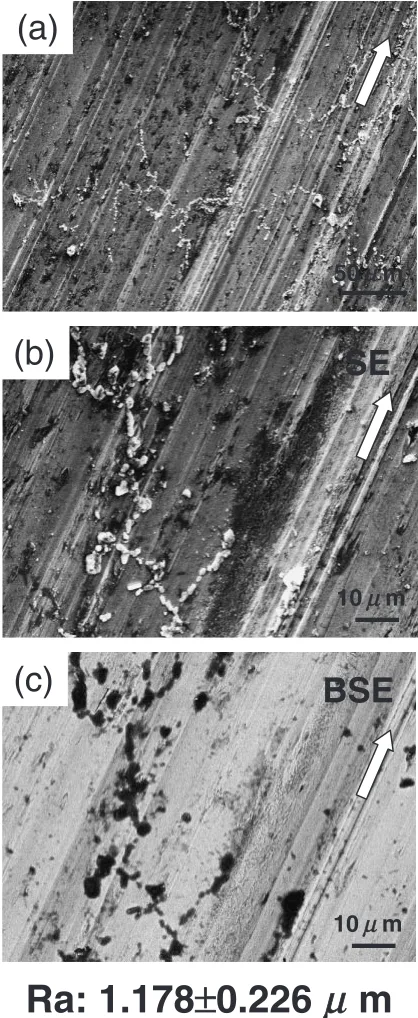
Figure 7 shows the SEM micrographs of the wear scar with argon bubbling: (a) wear scar, (b) magnified view of the wear scar, and (c) backscattered electron image of the magnified view. Although similar abrasive scratches are observed in the wear scar, the appearance of the worn surface with argon bubbling is apparently different from that with oxygen bubbling. Unlike the wear scar with oxygen bubbling, as shown in Fig. 5, a large amount of particles aggregating wear debris, appearing in white contrast in Fig. 7(a) and (b) and in black contrast in Fig. 7(c), are observed on the worn surface. The BSE black contrast of the aggregates in Fig. 7(c) corresponding to the SEM white contrast in Fig. 7(b) indicates that the aggregates are presumably oxidized mainly into Cr oxides, adhering to the worn surface during the wear process. Besides the aggregates, it is to be noted on the worn surface that a large amount of the smear-like contrast, colored dark grey, is concomitant with the scratches, which indicates that wear debris adheres to the wear surface during the wear process. This suggests that the adhesion of the wear debris is more prone to occur during the wear process with argon
bubbling,i.e.low oxygen content.
The surface roughness (Ra) on the worn surface after the
wear test with argon bubbling was measured to be 1.178mm,
a value much higher than that obtained with oxygen bubbling, which results from the formation of the aggregates and the wear debris adhering to the worn surface.
4. Discussion
In the present study, we have found that the wear volume is
higher under oxygen bubbling conditions,i.e.high dissolved
oxygen content, than under argon bubbling conditions. This result indicates that the wear behavior of the Co-Cr-Mo is extremely sensitive to the dissolved oxygen. Thus, in this section, we will discuss the influence of the dissolved oxygen content in distilled water on wear volume in the present tribosystem.
In general, surface oxide layers with a few nm in thickness
are possibly formed on the surfaces of Co-Cr-Mo alloys.24)
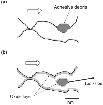
Thus, it is likely that dissolved oxygen content has an influence on the formation rate of the surface oxide layers. If the surface oxide layers appear between the pin and the disc, they weaken the adhesion of the wear debris. Figure 8 shows
5
µ
m
Fig. 6 SEM micrograph of the wear scar of the pin under oxygen bubbling conditions.
50
µ
m
10
µ
m
SE
10
µ
m
BSE
(c)
(b)
(a)
Ra: 1.178
±
0.226
µ
m
[image:4.595.64.273.71.229.2] [image:4.595.322.531.74.583.2]schematic drawings of wear debris staying between the disc and the pin in different surroundings. Fig. 8(a) illustrates the tribosystem surrounded by distilled water with low oxygen content, indicating the condition of argon bubbling. The adhesion of the wear debris to the disc or the pin can easily occur in low dissolved oxygen content (Fig. 8(a)), because the possibility of the direct metal-metal bonding between wear debris and pin and/or disc would be enhanced due to the suppression of formation of oxide film. Therefore, in the tribosystem in the surroundings with lower oxygen content, corresponding to the present wear test with argon bubbling, since the transfer of the wear debris from the disc (or pin) to the pin (or disc) readily occurs, the generation of the wear debris does not directly contribute to the wear volume, leading to apparently lower wear volume in the tribosystem with lower oxygen content than that with higher oxygen content; the transfer of the wear debris is not counted as wear loss, because the wear volume is estimated based on the loss in disc and pin weight during the wear test.
In contrast, the adhesion of the wear debris to the surface of the disc or the pin is disturbed under high dissolved oxygen content, because the formation of the oxide film on the surface of the wear debris and the disc and pin is facilitated due to the higher oxygen content in the surroundings (Fig. 8(b)). Thus, the wear debris can be easily emitted from the tribosystem during the wear test with oxygen bubbling. Accordingly, unlike the tribosystem with argon bubbling, the generation of the wear debris in the tribosystem with oxygen bubbling is more likely to contribute to the wear volume, leading to higher wear volume than in the tribosystem with argon bubbling.
Finally, we should note that the tribosystem, consisting of a pin-on-disc type wear testing machine as used in the present study and the Co-Cr-Mo alloy immersed in distilled water containing different dissolved oxygen content, is one which hardly ejects the wear debris and thereby traps the wear debris between the pin and the disc, which leads to apparently
lower wear volume than that actually worn without any transfer of the wear debris.
5. Conclusion
The wear volume with oxygen bubbling is approximately two times that with argon bubbling in spite of the fact that the same wear testing conditions were applied, which indicates that the lower oxygen content in the present tribosystem decreases the wear volume. The worn surfaces of the wear scar show transfer of the wear debris, adhesive wear, surface fatigue wear, and three-body abrasive wear, irrespective of bubbling conditions. The transfer and aggregation of the wear debris on worn surfaces, which would normally occur in the tribosystem using a pin-on-disc wear testing apparatus and does not contribute to an increase in wear volume, is more
pronounced in the tribosystem with argon bubbling (i.e.the
lower oxygen content) than in that with oxygen bubbling
(i.e. the higher oxygen content). Thus the transfer and the
aggregation of the wear debris are responsible for the lower wear volume than that actually worn without any transfer of the wear debris, as long as the the wear volume is estimated from the loss in disc and pin weight during the wear test. The oxygen bubbling in the distilled water enriches the oxygen content surrounding the worn surfaces, and thereby the oxide film formation on the surface of the disc and the pin, including the wear debris, is facilitated, leading to mitigation of the transfer of the wear debris and its aggregates to the disc and the pin. This mechanism is attributed to the increased emission of the wear debris out of the tribosystem, resulting in direct contribution to an increase in wear volume and therefore, higher wear volume than without oxygen bubbling.
Acknowledgement
The authors would like to thank Mr. Atsushi Kawamura, Mr. Shigeo Fujinuma, Dr. Tsukasa Ono, Mr. Masahiro Hotta and Mr. Takashi Iimura for technical assistance. This research was supported by a Cooperation of Innovative Technology and Advanced Research in Evolutional Area from the Ministry of Education, Science and Culture of Japan.
REFERENCES
1) F. Higuchi, A. Inoue and M. Semlitsch: Arch Orthop Trauma Surg116
(1997) 121–124.
2) D. Dawson, C. Hardaker, M. Flett and G. H. Isaac: The Journal of Arthoplasty19(2004) 118–130.
3) A. J. Saldivar-Garcı´a and H. F. Lo´pez: J. Biomed. Mater. Res.74A
(2005) 269–274.
4) H. Yokozaki, I. Katayama, K. Nishioka, M. Kinoshita and S. Nishiyama: J. Dermatol19(1992) 964–967.
5) S. Artik, C. von Vultee, E. Gleichmann, T. Schwarz and P. Griem: The Journal of Immunology136(1999) 1143–1152.
6) S. C. Scholes and A. Unsworth: Journal of Materials Science, Materials in Medicine,12(2001) 299–303.
7) J. H. Dmbleton:Tribology of Natural and Artificial joints (Elsevier 1981) pp. 223–226.
8) H. G. Willert, H. Bertram and G. H. Buhhorn: Clin Orthop258(1990) 95–107.
9) M. T. Clarke, C. Darrah, T. Stewart, E. Ingham, J. Fisher and J. F. Nolan: The Journal of Arthoplasty20(2005) 542–546.
Oxide layer
nm Adhesive debris
(a)
(b)
Emission
[image:5.595.67.269.76.281.2]10) L. D. Dorr, Z. Wan, D. B. Longjohn, B. Dubois and R. Maurken: J. Bone Joint Surg. Am.82(2000) 789–798.
11) C. B. Rieker, P. Ko¨ttig, R. Scho¨n, M. Windler and U. P. Wyss:
Alternative Bearing Surfaces in Total Joint Replacement, (ASTM 1346
STP, 1998) pp. 144–156.
12) C. B. Rieker, R. Scho¨n and P. Ko¨ttig: The Journal of Arthoplasty19
(2004) 5–11.
13) D. W. Howie, R. W. McGalden, N. S. Nawana, K. Costi, M. J. Pearcy and C. Subramanian: The Journal of Arthoplasty20(2005) 350–357. 14) L. P. Zichner and H. G. Willert: Clin. Othop.282(1993) 961–975. 15) K. R. Schultze, J. J. Callaghan, S. S. Kelley and R. C. Johnston: J. Bone
Joint Surg.75A(1993) 961–975.
16) A. Chiba, K. Kumagai, H. Takeda and N. Nomura: Materials Science Forum Vols.475–479(2005) 2317–2322.
17) C. T. Sims, N. S. Stoloff and W. C. Hagel:Super Alloys II, High
Temperature Materials for Aerospace and Industrial, New York,
(1987), pp. 135–163.
18) K. Kumagai, N. Nomura, T. Ono, M. Hotta and A. Chiba: Mater. Trans.
46(2005) 1578–1587.
19) A. Chiba, K, Kumagai, N. Nomura and S. Miyakaya: Acta Mater.55
(2007) 1309–1318.
20) A. Iwabuchi, T. Sonoda, H. Yashiro and T. Shimizu: Wear225–229
(1999) 181–189.
21) S. Mischler, A. Spiegel, M. Stemp and D. Landolt: Wear251(2001) 1295–1307.
22) D. Landolt, S. Mischler, M. Stemp and S. Barril: Wear256(2004) 517– 524.
23) D. Landolt, S. Mischler and M. Stemp: Electrochimica Acta46(2001) 3913–3929.