Accurate Evaluation of Copper Alloy Fluidity Using Automatic Pouring Equipment
with Improved Pouring Cup Heat Insulation
*Yuichi Motoyama
1, Tomoyuki Ozasa
2and Toshimitsu Okane
11Advanced Manufacturing Research Institute, National Institute of Advanced Industrial Science and Technology (AIST), AIST Tsukuba East, Tsukuba 305–8564, Japan
2Material Technology Group, Production Engineering Center, KITZ Corporation Nagasaka Plant, 2040, Yamanashi 408–8515, Japan
New pouring equipment was developed for the measurement of copper alloy fluidity. The fundamental characteristics of the developed equipment are the pouring cup system, which has high heat-retention, a stopper system without preheating, and a pouring temperature determi-nation system. In the evaluation of the developed device, the temperature of the molten copper alloy was decreased by 30 K from pouring to the stability of the measurement of the molten alloy temperature in the pouring cup. The rate of temperature decrease of the molten copper alloy in the pouring cup until the pouring temperature was 3.5 K/s. Experimentally obtained results demonstrated that the linearity between the super-heat above liquidus temperature and flow length improved compared with that reported from earlier studies. The standard deviation of flow length in the equipment was 20 mm. These results indicate that the effect of the casting conditions on flow length of the copper alloys will be evaluated accurately with the developed equipment. [doi:10.2320/matertrans.F-M2017802]
(Received October 25, 2016; Accepted January 6, 2017; Published March 25, 2017)
Keywords: copper, alloy, fluidity, shell mold
1. Background
For production of high-quality castings, molten metal should be filled without causing a short run. In this regard, various influential factors of casting conditions upon fluidity of the molten metal have been investigated to date. Fluidity evaluation methods of two types have been used. One method is the MIT method1), by which a quartz tube is inserted into
the molten metal to extract it under reduced pressure and to measure the distance along which the molten metal flows. One example of the other method is spiral-type fluidity test-ing2–8), by which molten metal is poured into a sand mold or
die having a spiral-shape cavity. Then the flow length is mea-sured. We used spiral-type fluidity testing in a sand mold, which is closer to actual casting conditions of the copper al-loys compared with the MIT method.
For the evaluation of fluidity of casting aluminum alloy, Isobe et al.2) used a shell mold having a spiral-shape cavity
and a device with stopper made of Isolite having high heat insulation property and pouring cup. With this device, alumi-num alloy is poured into a pouring cup installed directly above the pouring gate of shell mold, a stopper is drawn out at the point at which the molten metal temperature reached a target temperature while visually checking the indication of thermocouple fixed in the pouring cup. Pouring into the mold is performed. Then the flow length is measured. Additionally, some researcher tried to produce a device that provides good reproducibility for the evaluation of the aluminum alloy flow length. Sabatino et al.5) developed an automatic pouring
de-vice by which a stopper will open automatically when the molten metal temperature in the pouring cup reaches a prede-termined pouring temperature. Using this device, they evalu-ated the fluidity of ASTM A356.0 alloy and obtained results with good reproducibility. Bouska6) also developed a fluidity
testing device equipped with an automatic pouring
mecha-nism and investigated the influences of casting conditions upon the fluidity of Al-Si alloy. In these studies, a device with an automatic pouring mechanism is used. Therefore, opening of the stopper is unaffected by the skill of individual worker, thereby providing results with good reproducibility.
For copper alloy, a spiral-type fluidity testing device iden-tical to that used by Isobe et al. has been used7–9). Japan
Non-Ferrous Alloy Casting Association used the spiral-type fluidity testing device in the development of lead-free copper alloy and evaluated the influences of the degree of superheat upon fluidity of various copper alloys9). Influences of the
de-gree of superheat upon fluidity have been investigated empir-ically and theoretempir-ically. Those investigations have revealed that the degree of superheat and flow length can be represent-ed as the following Equation10).
Lf =
ρ[c(θc−θL)+fcHf]wS
h(θL−θ0)C (1)
In that equation, Lf stands for the flow length, ρ signifies the
molten metal density, c denotes the molten metal specific heat, w represents the flow velocity of molten metal, θc is the
molten metal temperature, θL stands for the liquidus
tempera-ture, θ0 is the mold initial temperature, C denotes the
circum-ferential length of the flow path, S is the cross-sectional area of flow path, fc is the critical solid fraction of the fluidity, Hf
denotes the latent heat of solidification, and h is the heat transfer coefficient.
However, results of tests performed by Japan Non-Ferrous Alloy Casting Association included a considerable degree of scattering and showed poor correlation between the flow length and superheat (Correlation coefficient R = 0.638– 0.994). Their results indicates that if the fluidity evaluation testing device used for aluminum alloy were used with no modification for the evaluation of fluidity of copper alloy, then the fluidity might not be evaluated correctly. A possible cause for scattering in the results obtained using the fluidity testing device is that the timing of pouring is determined by visual confirmation of the digital display of the thermocouple *
This Paper was Originally Published in Japanese in J. JFS 87 (2015) 855– 860.
amount of zinc, a constituent of many copper alloys, becomes greater if the degree of superheating is high. That difficulty suggests that an upper limit exists for the superheating from a target temperature. Fluidity tests are normally performed varying a degree of superheat from the liquidus temperature as a parameter. Therefore, the range of temperatures at which experiments can be conducted becomes narrower if tempera-ture reduction is excessive when pouring the molten metal in the pouring cup. In addition, the experimental temperature itself is high compared with that of aluminum alloys. There-fore, the temperature of molten metal in the pouring cup de-creases rapidly. The heat insulation performance of the pour-ing cup must be increased. Another problem is that the copper alloy melting temperature is higher than that of aluminum alloy. Therefore, anti-thermal shock properties of the pouring cup and stopper must be improved.
To overcome these difficulties, Ozasa et al.11) developed a
new spiral-type fluidity device for copper alloy. They im-proved the anti-thermal shock properties of the device and the heat insulation performance of the pouring cup that consisted of a steel shell, a heat-insulate sleeve, and a heat-insulate board. However, the Japanese Industrial Standard (JIS) CAC406 alloy flow length measured using this spiral-type fluidity testing device under the same experimental condi-tions is 236–485 mm, which suggests considerable scatter-ing. For that reason, accurate results were not obtained. A shortcoming of the device developed by Ozasa et al. is that the accurate pouring temperature is not obtained when the molten alloy temperature in the pouring cup is reduced rapid-ly because the worker visualrapid-ly checks an indication of the thermocouple output to ascertain the pouring temperature. The degree of worker proficiency for manual opening by lift-ing up the stopper is also considered to be responsible. The graphite bar without pre-heating was used as the stopper be-fore each experiment. This might lead to produce irregulari-ties of the molten alloy temperature in the pouring cup, there-by affecting the results. However, preheating of the stopper is not preferred from the perspective of experimental efficiency and reproducibility. In addition, they did not discuss the issue of the extent to which the degree of superheat can be sup-pressed for pouring temperatures to the mold. This issue is extremely important for fluidity testing device for copper al-loy from the perspective of the vaporization of zinc. However, no mention of this evaluation item is made in their report.
The discussion presented above has revealed the following requirements, which must be met for fluidity evaluation test-ing devices for copper alloy: The pourtest-ing cup must retain heat and be resistant to thermal shock during pouring the molten alloy into the cup. Some mechanism must secure the stopper by other than manual means and must allow opening. Some mechanism must be provided to allow molten alloy
evaluate the temperature reduction of the molten copper alloy from pouring the molten copper alloy into the pouring cup to exhibiting the maximum temperature of thermocouples mounted in the pouring cup. Temperature reduction rate of the molten alloy retained is also evaluated until it is poured into the mold. To determine the pouring temperature correct-ly, we evaluate the pouring temperature determination mech-anism when the stopper is lifted up. Moreover, scattering of the flow length under identical conditions is evaluated. Then influences of the degree of superheating above liquidus tem-perature on flow length are evaluated. We then demonstrate that the developed device is suitable for evaluation of the flu-idity of copper alloy.
2. Composition of Developed Device
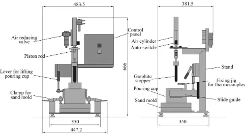
Regarding difficulties that arise when the fluidity evalua-tion testing device for aluminum alloy described above is ap-plied to copper alloy, anti-thermal shock properties and dura-bility of the pouring cup are improved by the heat insulation sleeve, heat insulation board, and steel shell. Moreover, heat retaining performance is improved by the use of a large ca-pacity pouring cup. An air cylinder is used for stopper fixing and lifting up to minimize scattering of the measurement re-sults attributable to differences in the degree of proficiency of different workers. A signal of the piston rod working timing detected by a sensor (auto-switch) is output. Simultaneously, the melting temperature in the pouring cup is recorded to pre-vent errors in molten alloy temperature determination attrib-utable to visual confirmation of the thermocouple output by a worker.
Figure 1 depicts the device we developed, consisting pri-marily of a pouring cup, stopper and air cylinder, and a shell mold having a spiral-cavity. Figure 2 presents details of the pouring cup, which consists of a heat-insulation sleeve (Iso-lite sleeve #1260; Iso(Iso-lite Insulating Products Co. Ltd.), heat-
[image:2.595.306.548.629.761.2]insulation board (Isolite board #1260; Isolite Insulating Prod-ucts Co. Ltd.) having the ϕ18 mm penetration hole for molten metal flowing from the pouring cup to the shell mold, and a steel shell. A jig is also provided for insertion and fixing of two thermocouples from above the molten metal surface. Av-erages of temperatures measured by two grounding type sheath thermocouples (K-type, T35051; Sakaguchi EH VOC Corp.) having ϕ0.5 mm sheath diameter and 100 mm length are used as the molten alloy temperature in the pouring cup. The pouring cup is moved by sliding on the guide of stand and proper to allow easy fixing and removal. A lever for lift-ing up and down the pourlift-ing cup is provided to the stand, which is used for setting of the pouring cup and for removal of the remaining molten metal in the pouring cup after flow-ing of the molten metal ceases.
The graphite stopper is fixed to the piston rod. In the mech-anism, the stopper is moved upward by manipulating the switch on the operation panel. The molten metal in the pour-ing cup is poured into the shell mold. A sensor is provided for the air cylinder to output a voltage signal while the piston rod is moving. This voltage signal is read simultaneously with measurement by the thermocouple (sampling time: 100 ms) so that reading of molten alloy temperature at opening of the stopper can be read out from the measurement record after completion of the experiment. As presented in Fig. 2, the graphite stopper must be set in advance at the predetermined location in the pouring cup, and preheating is difficult be-cause of the structure. Therefore, reduction in the molten al-loy temperature at pouring the molten alal-loy into the pouring cup presents a concern. In fact, experimentally obtained re-sults that will be discussed later show that reduction in the molten alloy temperature are significant. Then, for the im-provement of molten alloy temperature reduction rate, we at-tempted to reduce heat transfer from the molten metal to the stopper by winding heat-insulation wool (5 mm thickness, IBI wool blanket #1260, Isolite Insulating Products Co. Ltd.) around the stopper in advance, as depicted in Fig. 3.
Figure 4 portrays a shell mold, with a spiral-cavity, used in the test. It has flow length of 1,850 mm. The upper face of the upper mold has a server-like configuration to prevent drop-ping of molten metal removed from the pouring cup from the upper surface of the mold when it is discharged after flowing ceases. Although back pressure is generated during pouring, which might affect measurement of the flow length, the gas vent hole is not provided specifically to the shell mold consid-ering that gas will be vented from the partition to some gree. Figure 5 presents the external appearance of actual
de-vice.
3. Experimental Conditions
A Cu-26 31%Zn-0.5 0.8% system alloy (liquidus line temperature: 1,197 K) was used for measurements of the molten alloy temperature drop when poured into the pouring cup. The cooling rate of the molten alloy temperature in the pouring cup was measured until pouring into the mold, along with verification of the molten alloy temperature measure-ment mechanism and verification of the reproducibility of flow length measurement results. An ingot (1 kg) was melted in graphite crucible using a high-frequency melting furnace. The melting temperature was set to 1,400 K. After the melt-ing temperature was reached, the crucible was removed usmelt-ing a tongs. Then pouring into the pouring cup was performed promptly. According to the calculations, the molten metal Fig. 2 Interior dimensions of the pouring cup and shell mold.
Fig. 3 (a) Original stopper and (b) improved stopper with insulation.
Fig. 4 Spiral shell mold used for fluidity tests.
[image:3.595.70.268.71.186.2] [image:3.595.331.522.74.206.2] [image:3.595.328.526.251.368.2] [image:3.595.340.513.417.545.2]perature of the molten metal in the pouring cup stabilized, the temperature drop up to 1,298 K (liquidus temperature + 101 K), which has the lowest degree of superheat in this ex-periment, was divided by the time needed for its drop. Re-garding the reproducibility of flow length measurement re-sults, experiments were conducted six times under liquidus temperature + 120 K to check the reproducibility. Thermo-couples were installed at several locations in the spiral cavity in the form of a touch sensor. The flow rate was measured using these sensor data. The average flow rate of 559 mm/s was obtained. It is considered from this result that about 0.7– 1.5 s elapses after the stopper moved up until the flowing ceases.
An evaluation of the influences of the degree of superheat upon flow length was performed using JIS CAC804 alloy (1,153 K liquidus temperature) and JIS CAC406 alloy (1,283 K liquidus temperature). The amount of melt was set to 1 kg. Pouring into the pouring cup was performed at a liq-uidus temperature +200–240 K. Pouring to the shell mold was applied at three levels in the range of liquidus tempera-tures +100–200 K. For deoxidizing with CAC406, 0.2 mass% of Cu-15%P was added immediately before pouring into the pouring cup. Correlation between the obtained flow length and the degree of superheat was evaluated.
4. Results of Experiments and Discussion
4.1 Reduction of molten alloy temperatures in the pour-ing cup
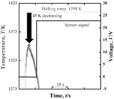
Figure 6 presents results of molten alloy temperature mea-surements in the pouring cup when Cu-26 31%Zn-0.5 0.8%Bi system alloy was poured into the cup where
heat-in-As causes of molten metal temperature reduction, Heat transfer from molten metal to pouring cup, Heat transfer from molten metal surface to atmosphere, and Heat transfer from molten metal to graphite stopper are considered pri-marily. A temperature rise checked by touching the steel shell with the bare hands was slight. Therefore, heat transfer from the molten metal to the pouring cup was excluded as a possi-ble primary cause. Regarding heat transfer from the molten metal surface to the atmosphere, separate tests were conduct-ed while wool was wound around the graphite bar to take temperature measurements of the molten metal being retained in the pouring cup by sheath thermocouples provided at 2 mm, 9 mm, and 18 mm height from the bottom of the pour-ing cup.
[image:4.595.68.268.588.762.2]Results showed that the temperature at 18 mm height is lower than that of 2 mm from the bottom by, at most, 3 K, which is a gentle gradient compared with the temperature gradient in the internal radius direction of the pouring cup, as addressed later. Therefore, heat transfer from molten metal surface to the atmosphere was judged as not a primary cause. For discussion of the heat transfer from the molten metal to the graphite stopper, Table 1(a) presents the molten alloy temperature detected by thermocouple 1 immediately before pouring into the shell mold (17 mm distance from the graph-ite stopper) and thermocouple 2 (25 mm distance from the graphite stopper). The temperature sensed by thermocouple 2 is about 10 K lower than that of thermocouple 1, which is located closer to the graphite stopper. This result suggests that a large temperature gradient is generated to the molten metal around the stopper because of heat transfer from molten met-al to graphite stopper. In addition, observations conducted after the experiment revealed that copper alloy solidified along with the stopper circumference and bonded, suggesting that heat transfer from the molten metal to the graphite stop-per is generated.
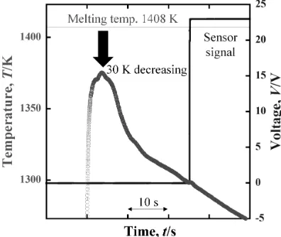
Figure 7 presents results of the molten alloy temperature measurement when pouring was performed with heat-insulat-ing wool wound around the stopper. A 30 K temperature re-duction from pouring into the cup was observed before the molten alloy temperature stabilized. Improvement of the tem-perature drop by about 15 K was achieved in comparison with a case in which no insulating wool is wound. That result indicates the possibility of pouring the molten alloy to the
Table 1 Measurements of the pouring temperature of both thermocouples with and without stopper insulation.
Thermocouple 1 (K) Thermocouple 2 (K) (a) Without insulation 1290.6 1300.4
(b) With insulation 1298.1 1298.6
[image:4.595.304.549.749.788.2]pouring cup with a lower degree of superheat with regard to the target temperature. The cooling rate from stabilization of measurements of the molten alloy temperature to the tem-perature of pouring into the mold is 3.5 K/s, which is about one-third of that of a case in which no insulation wool is wound, suggesting improved heat retention. As a result, pour-ing at the target temperature was accomplished with compar-ative ease. Temperature measurements by thermocouple 1 and thermocouple 2 immediately before pouring into the mold are presented in Table 1(b). Differences of the measure-ments are around 0.5 K which demonstrates that molten alloy temperature in the pouring cup are more uniform than they are when no wool is wound.
The results described above revealed that if insulating wool is wound around the stopper, then the copper alloy fluidity can be evaluated without pre-heating while preventing the temperature drop of molten metal in the pouring cup. In gen-eral, conditions of alloy and pouring temperature are varied in the fluidity test. This means that experiments are conducted several times. Therefore, the fact that tests are possible with-out pre-heating of the stopper is meaningful from the per-spective of the repeatability of experiments. The following experiments were performed with insulating wool wound around the stopper.
4.2 Verification of the pouring temperature measuring mechanism
Figure 8 portrays changes of the molten alloy temperature in the pouring cup and in the sensor voltage signal over time. As the figure shows, voltage rose suddenly from 0 V at a cer-tain time. This voltage signal indicates the opening of stopper. If the molten alloy temperature in the pouring cup at the volt-age signal rise is checked after the experiment, then the pour-ing temperature at which the molten metal is poured into the shell mold can be ascertained. Results show that, using this mechanism, determination of the pouring temperature by vi-sual confirmation of reading of the thermocouple output during experimentation is unnecessary. Errors that might be caused at pouring temperature determination might be re-duced. In Fig. 8, a molten alloy temperature rise of about 0.5 K is noticed when the stopper moved up, presumably
be-cause of the existence of slight temperature distribution of the molten metal in the pouring cup described previously. The temperature field is disturbed by convection of molten metal that occurred with the stopper rising.
4.3 Reproducibility of flow length measurements
Using Cu-26 31%Zn-0.5 0.8%Bi system alloys, the flow length at 120 K of superheat was measured six times. Table 2 presents the results as averages and standard deviations. Re-sults of the study performed with the automatic pouring mechanism using aluminum alloy described previously are also shown here5,6). The standard deviation of flow length
ob-tained with this device is either equivalent to or less than that. This results indicate that the flow length can be evaluated also with copper alloy with similar reproducibility to that obtained using a device equipped with an automatic pouring device used for aluminum alloy.
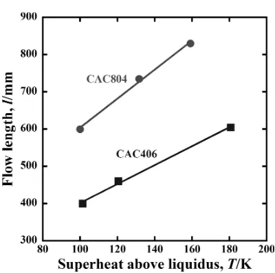
4.4 Influences of the degree of superheat on flow length
Figure 9 depicts the influences of the degree of superheat above liquidus on the flow lengths of CAC406 and CAC804. This figure shows specifically that CAC804 has better fluidity than that of CAC406. The test was performed only once for each degree of superheat. Therefore, direct comparison with conventional studies is difficult. However, correlation as high as R = 0.998 was obtained in terms of the fluid length and the degree of superheat of each alloy in this study. The correla-tion coefficient obtained in the experiment by the above-men-tioned Japan Non-Ferrous Alloy Casting Association is R = 0.638–0.994. This fact indicates that the developed device Fig. 7 Temperature drop of the melt in the pouring cup with stopper
[image:5.595.68.266.71.238.2]insula-tion and the sensor signal of the auto-switch. Fig. 8 Determination of pouring temperature using an auto-switch signal.
Table 2 Comparison of reproducibility of flow length measurements be-tween this study and earlier studies.
Average length (mm)
Standard deviation
(mm) Casting alloy This Study
(N = 6) 470 20 Cu-Zn-Bi
Sabatino et al.
(N = 20)5) 540 30 A356
Bouska
[image:5.595.321.524.71.240.2] [image:5.595.305.549.310.398.2]evaluated the influences of the degree of superheat upon flu-idity more accurately than the conventional fluflu-idity testing device for the copper alloy. It is expected from this fact that this device can produce more accurate evaluation of the influ-ences of each factor of casting upon the fluidity for copper alloys.
5. Conclusions
Several difficulties arise when a conventional fluidity eval-uation device designed for aluminum alloy is used for copper alloys. In our development of a device for copper alloy fluid-ity evaluation, we addressed these difficulties. The device provides the following features.
(1) Employment of a pouring cup composed of a heat insula-tion sleeve, a heat insulainsula-tion board and a steel shell is helpful for improvement of anti-thermal shock properties and durability for pouring of copper alloy, with its higher melting temperature.
(2) Opening a stopper using air cylinder eliminates the influ-ence of a worker s degree of proficiency upon experimen-tally obtained results.
(3) Because of synchronization of the signal from the sensor provided to the air cylinder and measurement of molten alloy temperature, the temperature of the molten metal being poured into the mold can be determined accurately after completion of the experiment. As a result, errors in the pouring temperature determination are prevented. (4) A graphite stopper that needs no pre-heating, with
(2) Because of the stopper with heat-insulate wool wound around it, the cooling rate of the molten metal being re-tained in the pouring cup is 3.5 K/s, which eases pouring at the target temperature.
(3) The standard deviation of flow length measurements ob-tained from experiments conducted under identical con-ditions is 20 mm, which is equal to that obtained with a conventional device used for aluminum alloy flow length evaluation.
(4) For CAC406 and CAC804, the relation between flow length and degree of superheat, which theoretically share a proportional relation, was checked using this device. Higher correlation was obtained.
Experiment results and the discussion presented above in-dicate that copper alloy fluidity can be evaluated more effi-ciently and accurately using this device than when using a conventional device for copper alloy fluidity evaluation.
Acknowledgment
The authors wish to thank Mr. M. Ebata, National Institute of Advanced Industrial Science and Technology (AIST), who cooperated with us in conducting the experiments.
REFERENCES
1) M.C. Flemings: Solidification Processing, (McGraw-Hill Inc., 1974). 2) T. Isobe, M. Kubota and S. Kitaoka: J. JFS 47 (1975) 345–355. 3) A.K. Dahle, P.A. Tøndel, C.J. Paradies and L. Arnberg: Metall. Mater.
Trans., A 27 (1996) 2305–2313.
4) F. Binczyk, M. Cieśla, P. Gradoń and R. Findziński: Archives of Found-ry Engineering 14 (2014) 9–12.
5) M. Di Sabatino, F. Syvertsen, L. Arnberg and A. Nordmark: Int. J. Cast Metals Research 18 (2005) 59–62.
6) O. Bouska: Metalurgija 14 (2008) 17–30.
7) S. Oya, M. Sayashi, H. Kambe and K. Hosaka: J. JFS 52 (1980) 107– 112.
8) H. Kambe, K. Mochizuki, S. Abe and S. Oya: J. JFS 58 (1986) 775– 780.
9) The materials process technology center report 567 (2001) 33. 10) E. Niyama: Chuzo dennetsu kogaku, (AGNE Gijutsu Center, Tokyo,
2001) p. 197.
11) T. Ozasa, T. Okane, A. Hirose, S. Totani and H. Kato: Report of 158th JFS Meeting (2001) p. 19.
[image:6.595.68.268.62.261.2]