Compressive Deformation Simulation of Regularly Cell-Structured Materials
with Various Column Connectivity
Kanyatip Tantikom and Tatsuhiko Aizawa
Center for Collaborative Research, The University of Tokyo, Tokyo 153-8904, Japan
A finite element method is developed to understand the in-plane, quasi–static compressive deformation mechanism and to predict elasto– plastic stress–strain responses of regularly cell-structured honeycombs. Temporal evolution of geometric configuration is also observed in series in order to understand its deformed pattern. Elasto–plastic model predicts quantitatively the compression behavior of copper cell-structured materials. Fairly good agreement with experimental results assures the validity of the present approach. Four different cell geometries are employed to discuss the effect of column-connectivity in a unit cell on the initial and shear localization behavior of cellular materials. In the case of cellular materials with four-edge connectivity, their initial and post-yielding behaviors are governed by buckling and bending deformation of one selected column. In the case of six-edge connected cellular materials, a set of columns is selected among six in the unit cell to make buckling and bending deformation in the dependent manner on loading directions. This leads to plastic anisotropy of this type of cellular materials.
(Received December 24, 2004; Accepted March 14, 2005; Published June 15, 2005)
Keywords: cell-structured materials, elasto–plastic analysis, compressive deformation, initial yielding, post-yielding, shear localization, plastic anisotropy, column-connectivity
1. Introduction
The open and closed cellular materials have been high-lighted because of their extremely lightweight. Among variety of geometrical configurations, a periodically cell-structured material is thought to be noticed in the recent research and development.1–4)Because of its regular micro-truss architecture, two-dimensional periodic channels and designated linear microstructure, it exhibits mechanical properties highly superior to the conventional metallic foams and cellular materials with randomly truss-connected cells. In particular, those cellular foams and open/closed cell-struc-tured materials have lower mechanical properties when their relative density becomes below 0.3.5)Furthermore, this new
type of cellular materials is rationally adaptive to engineering applications since its mechanical and functional properties are likely predictable and designable by using the unit-cell modeling and homogenization theory.6,7)
The mechanical behavior of cell-structured honeycombs has been widely studied for application to core material as lightweight structural sandwich beams.6–8)This mechanical response is determined by its cell configuration and the matrix properties in cellular solids. Different from the solid materials,8,9) compressive deformation mode of the cell-structured materials changes from uniform plastic deforma-tion to localizadeforma-tion. Cell geometric topology affects on this deformation mode change and localization modes.
Various periodic cellular metals with different topologies have been studied to optimize the cellular core structures.7)In
particular, Gibsonet al.,8)studied the mechanical behavior of
hexagonal honeycombs and stressed the effect of relative density and/or cell wall thickness on the stress–strain response. They also represented elastic anisotropy as a function of in-plane directivity for triangular, square and hexagonal unit cell structures. Wadleyet al.,6)designed and developed various periodic cell-structures for core materials since they have preferable benefits in higher specific strength at low relative density. Recently, linear cellular materials (LCMs) are fabricated as a two-dimensional complex-shaped
honeycomb via the non-metallic powder paste extrusion and subsequent, direct reduction. This process provides us to make near-net shaping of cell-structured materials with significantly more complex distributions of cell shapes and size as well as precision of cell alignment and wall thick-ness.3,7,10,11)Their in-plane mechanical properties including effective elastic stiffness and initial yield strength were first investigated to point out the importance of cell geometry in their elasto–plastic deformation mechanism.7,10–12)
In the present paper, the computational mechanics model-ing is proposed to discuss the effect of unit cell geometry on the uniform compression in plane–strain condition. Four different cell geometries were selected to study their elasto– plastic properties. The temporal evolution of geometric configuration was also observed in series to demonstrate the deformed pattern during compression.
2. Theoretical Modeling and Experiments
2.1 Numerical method
The finite element method is used to theoretically under-stand the experimental responses of cellular materials and to make cell-topological design. Two-dimensional quasi–static analysis model is developed to describe the elasto-plastically collapsing behavior of cell-structured materials. As had been discussed in literatures,7,9) the effect of cellular geometric
configuration on the plateau stress and strain is thought to be much important in addition to the relative density and matrix alloy yielding stress. In the present theoretical model, both materials and geometric non-linearitries are directly consid-ered to describe the elasto–plastic collapsing, yielding and bending deformation before final densification process. The calculated series of deformed configuration in cells demon-strates the effect of initial cellular geometry on the deformation mode. Furthermore, the calculated relationship between macro–stress and macro–strain is compared with the measured mechanical response in quasi–static compression test.
The related computational conditions are summarized in
Table 1. Each cell wall was subdivided into the finite elements. Contact and target elements were used to trace the change of contact state in deforming cell. The target-element was utilized to predict the possibility of penetration of one cell-element to the others. Cell wall material was assumed to be elasto–plastic with the J2-flow theory. Its stress–strain
contribution was characterized by Young’s modulus (E) while the elasto–plastic response was modeled by plastic modulus (K). The model is compressed by upper rigid bar. The bottom side of the cell-structured model was fixed and the upper bar was controlled to press the finite element model with the prescribed incremental displacement. On the sides parallel to the loading direction, no displacement conditions were prescribed with consideration of experiments. Figure 1 depicts the finite element model and typical boundary conditions in X1 and X2 directions. Temporal evolution of
geometric configuration was obtained in series by this displacement control. In general, collapsing deformation is rather sensitive to imperfections embedded in cell walls and geometric configurations. No initial imperfections were considered in the numerical models.
2.2 Selection of unit-cell model
Four regularized, cell-structured materials are selected as a representative model to study their compressive deformation responses with respect to quasi–static loading inX1 andX2
directions: a triangular cell, a square cell, a rectangular cell, and a diamond cell. A model with seven rows and seven columns is enough for regularly cell-structured models to investigate nonlinear response in compression. The size effect is diminished when the specimen size of regularly cell-structured materials is greater than55arrays in cells.13–15)
2.2.1 Square unit cell
Relative density of square unit cell,R, is defined by2t=l
wheretis the cell wall thickness andlis the cell wall length of the cellular structure.12)The square cell-structured model
consisted of a total of 49 cells with 112 beam elements and 22,422 nodes. Figure 2a) depicts this square cell-structured material:R¼0:28,t¼9:0mm andl¼65:0mm.
2.2.2 Triangular unit cell
Relative density of triangular unit cell, R, is defined by
2pffiffiffi3t=l.12)This triangular cell-structured model consisted of a total of 91 cells with 172 beam elements and 30,389 nodes. Figure 2b) depicts this triangular cell-structured material:
R¼0:37,t¼7:5mm andl¼69:0mm.
2.2.3 Rectangular unit cell
Relative density of the rectangular unit cell structure,R, is
defined approximately by ðhthþltlÞ=hl where t is the cell
wall thickness,lis the cell wall length andhis the cell wall height. The rectangular cell-structured model consisted of a total of 49 cells with 112 beam elements and 14,212 nodes. Figure 2c) depicts this rectangular cell-structured material with the geometric aspect ratio:R¼0:37,t¼8:5mm,l¼
69:0mm,h¼34:5mm andl=h¼2:0.
2.2.4 Diamond unit cell
Relative density of the diamond unit cell structure,R, is
defined approximately by5t=pffiffiffi3l. The present diamond cell-structured model consisted of a total of 28 diamond-shaped cells and 56 triangular cells with 168 beam elements and 25,045 nodes. Fig. 2d) depicts the cross-section of diamond cell-structured material: R¼0:32, t¼8:8mm and l¼
80:0mm.
2.3 Experiments
2.3.1 Sample preparation
The copper cell-structured honeycombs were prepared by REDOX-forming process.11)Copper oxide paste, mixture of
Cu2O powders and binders, was loaded to a 55 mm diameter
[image:2.595.307.546.81.162.2]extruder with triangular and square cell dies. Forward-extrusion was carried out at a speed of 1.5 mm/min to form the green billets. The reduction of extruded specimens was carried out in a hydrogen furnace. The green billets were sintered at 1123 K (850C) for 3 h with the heating rate of Table 1 Computational conditions.
Program system Type of element
ANSYS6.1
Triangular element with 6 nodes
Young’s modulus E¼100GPa
Poisson’s ratio ¼0:35
Yield strength 60 MPa
Stress–strain curve Bilinear isotropic hardening (rate independent plasticity)
Plastic modulus K¼3GPa
Friction coefficient 0.3
Yielding condition J2flow theory
u2 u1
X2
X1
Fig. 1 Finite element models of regularly cell-structured materials. The left panel shows typical boundary condition for compression in theX1 direction while the right panel shows those for compression in theX2 direction.
X2
X1
(a) (b)
(c) (d)
[image:2.595.305.547.232.428.2]7C/min. All samples were cooled in furnace under a
controlled atmosphere. Figure 3 shows the copper cell-structured honeycombs with square and triangular cells after reduction. The average specimen had the width of 23.5 mm, the height of 23.5 mm and the length of 20 mm. The relative density of cell walls is 92–95% T.D. and their purity is 99.9%.
2.3.2 Compression testing
The fabricated cell-structured honeycombs were subjected to compression at a quasi–static rate of 0.5 mm/min. Mechanical tests were carried out by the universal testing machine (Autograph, Shimadzu) at room temperature. The deformed configurations of specimens were taken by digital camera during testing. Macro–stress and macro–strain was calculated by dividing the applied force by its cross-sectional area. Since the length of specimen is much more than the unit cell length, its in-plane compression is considered to be a mechanical response under plane strain condition.
3. Theoretical Understanding of Experimental Results
[image:3.595.306.547.75.268.2]Compressive deformation of triangular and square cell-structured honeycombs is investigated in order to compare its theoretical prediction with experiments.
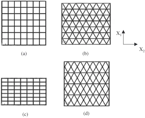
Figure 4 shows the specific compressive stress–strain relations along with the sequences of deformed configura-tions for square copper cell-structured materials. Fairly good agreement is recognized between the experimental response and the theoretical prediction. In experiments, the forward extruded specimen with the square-cell array of 12 rows and 12 columns was subjected to uniaxial in-plane compression. The outer cell wall thickness is designed to be thicker than that of inner ones in order to promote the stiffness in compression. In the linear elastic regime, uniform deforma-tion takes place throughout the specimen. Beyond the first maximum stress, deformation in the specimen begins to localize itself. Cell walls in the weakest row instantly collapse, and, results in the rapid drop of stress. In experi-ments, the collapsing deformation advances skew in the cell arrays of specimen, while it does rather normal in compu-tation. To be discussed later, this is caused by the sensitivity of column-connectivity in the triangular cells to geometric imperfection. Since the cell walls have a small curvature in column, a skew collapsing mode is selected in experiments.
This experimental behavior is quantitatively described by the present theoretical model. The cells, locally collapsing in the asymmetric shearing mode, form the localized band of deformation. While, deformation still remains symmetric and homogeneous in the rest parts of specimen away from this zone. This collapsing mode was similar to that found in other investigations; square-arrayed specimens collapsed row-by-row and large drop of stresses was observed repeatedly in the measured and calculated stress–strain relation.7,11)
Figure 5 depicts the specific compressive stress–strain relations together with the sequences of deformed config-urations for triangular copper cell-structured material. In experiments, plastic collapsing deformation initiates near the center of specimen, and, gradually propagates to adjacent cells in the specimen until all cells are collapsed. Overall, the calculated responses are in good agreement with the experimental results. Due to porosity of the cell wall copper matrices, the stress level becomes lower in experiments.
(a)
(b)
Fig. 3 Pure copper cell-structured honeycomb with (a) square, and (b) triangle unit cells.
0.0 10.0 20.0 30.0 40.0 50.0 60.0 70.0
0.00 0.10 0.20 0.30 0.40 0.50
Specific compressive stress, MPa
Nominal compressive strain
Simulation
Experiment
εc=0.00 εc=0.05 εc=0.10 εc=0.15 εc=0.20 εc=0.25
Fig. 4 Specific stress–strain responses and temporal deformed configura-tions of triangular cell-structured materials.
εc=0.00 εc=0.05 εc=0.10 εc=0.15 εc=0.20 εc=0.25
[image:3.595.48.289.76.213.2] [image:3.595.307.548.556.758.2]Since most of cells other than locally collapsing band uniformly deform, macro–stress increases with macro–strain in both experiment and simulation results.
From the above agreement between two, topological effects of cells on their compressive mechanical response is quantitatively evaluated by the present approach.
4. Results
Three types of cell-structured configurations are employed to describe their compressive deformation behavior. Effect of geometrical topology on anisotropic response is also inves-tigated by simulations with two types of compressive loading inX1 andX2directions.
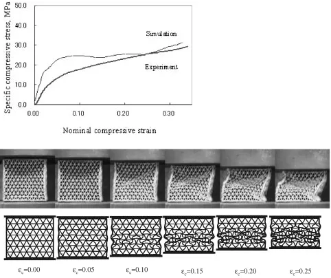
[image:4.595.307.547.74.252.2]4.1 Triangular unit cell structure
Figure 6 depicts the stress–strain response together with the sequences of deformed configurations of regularly triangular cell-structured models under X1 andX2 loading
directions. Initial deformation is homogeneous in models. Since the specific elastic modulus is indifferent to loading directions, the triangular cell-structured materials are elasti-cally isotropic.
In the elasto–plastic response, six cell-walls in the triangular cell-topology bend around their vertices. This bending deformation propagates to adjacent triangular con-nectivity and forms a shear band. Different from the shear localization in Fig. 4, this localization takes place in the cooperative manner of bending and shear-collapsing. In the following, this localization is called a bent-shear-mode localization. Once this localization propagates in the system, the whole specimen becomes mechanically unstable. In the triangular cell-structured topology, however, work hardening is seen in the post-localization regime. This might be because an additional plastic work is needed for elasto–plastic propagation of this bent-shear-mode localization.
In the case of compressive loading inX2direction, single bent-shear-mode localization was seen. This implies that
localization occurs in the narrowed area. Considering that the initial yielding is sensitive to deformation mode change, decrease of initial compressive stress in X2 loading is attributed to early transition from uniform compressive deformation to narrowed localization with the single bent-shear-mode. Two or three localized bands are seen when loading in the X1 direction. This difference has close relationship with kinematics of column connectivity in two directions.
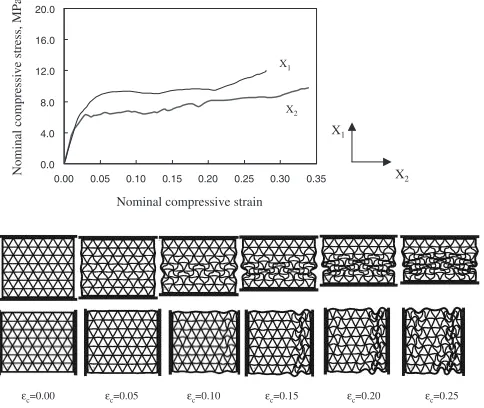
4.2 Rectangular unit cell structure
Figure 7 depicts the stress–strain curves and the sequences of deformed patterns of regularly rectangular cell-structured models under X1 and X2 loading directions. The weakest
vertical cell column begins to collapse shortly after the elastic limit. Plastic buckling of a whole system occurs by cell collapsing, and, this results in the rapid drop of stresses beyond the maximum yielding stress. Thereafter, nearly the constant stress state is achieved during this shear collapsing deformation in row-by-row until all the cell walls come into contact. This stress–strain characteristic is nearly similar to the square cell-structured materials.
As seen in Fig. 6, the yielding behavior is sensitive to initial cell-wall compression mode. Due to narrowed shear localization, the yielding stress is lowered in the case of the
X2-loading.
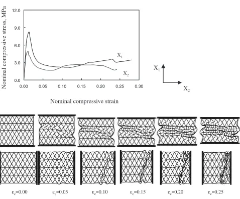
4.3 Diamond unit cell structure
Figure 8 shows the stress–strain relationships along with the sequences of deformed shapes of regularly diamond cell-structured models in theX1andX2 directions. The network of diamond cell configuration has two types edge-connec-tivity: four edge and six-edge connections. When loading this cellular material in the X1 direction, the cell walls having edge-connectivity of 4 initiate to locally bend round the vertices. Since a bending moment reaches to fully plastic moment, macro–stress rapidly drops beyond the elastic limit. In posterior to yielding, collapsing deformation propagates to adjacent cells and adjacent rows. On the other hand, plastic buckling occurs at the weakest vertical cell column when
εc=0.00 εc=0.05 εc=0.10 εc=0.15 εc=0.20 εc=0.25
0.0 4.0 8.0 12.0 16.0 20.0
0.00 0.05 0.10 0.15 0.20 0.25 0.30 0.35
Nominal compressive stress
, MPa
Nominal compressive strain
X2 X1 X1
X2
Fig. 6 Nominal compressive stress–strain responses and temporal de-formed configurations of triangular cell-structured materials inX1andX2 directions.
Nominal compressive stress, MPa 0.0 5.0 10.0 15.0 20.0 25.0
0.00 0.10 0.20 0.30 0.40 0.50
Nominal compressive strain
X2 X1
X1
X2
εc=0.00 εc=0.05 εc=0.10 εc=0.15 εc=0.20 εc=0.25
[image:4.595.49.291.545.749.2]loading in theX2 direction. Severe localization is found to occur along the diagonal in the cellular structure with an angle of 60 to the X1-axis. This localization results in the
relatively low loading capacity. The difference in deforma-tion mode between two is caused by topological geometry to loading.
5. Discussion
Four types of regularly cell-structured materials were investigated to explore in-plane compressive stress–strain responses and their deformed configurations.
In the elastic region, deformation takes place in uniform isotropic manner. This leads to the indifferent effective moduli to two loading directions, as reported in Table 2.12)In
the elasto–plastic region, transition from uniform, symmetric to asymmetric deformation modes, gives rise to anisotropic response. In the theoretical modeling, no geometric imper-fection is present in the model. Deformation usually initiates near the center of cell-structured model for theX1 loading. The deformation of adjacent cells to the punches is con-strained by the loading motion of the punch; so that the top and bottom end rows have higher stiffness than other inner cells. In the X2 loading, cell-structured model initially
buckled and collapsed in the upper zone of the model. This is due to the difference cells alignment between two loading directions. The loading motion of upper punch gives rise to the bending of a single column along the loading direction.
This deformation develops and propagates to form a localized deformation band. The localized deformation pattern is strongly dependent on the cell geometry. Table 3 lists specific plateau stresses of various cell-structured honeycombs in X1 and X2 loadings. Rectangular
cell-structured model has the highest specific plateau stress in the X1 direction, followed by triangle cell, square cell and
diamond cell, respectively. The specific plateau stress value might represent the loading capacity of these cell-structured models.
In the case of the triangular cell-structured materials, deformation mode changes from uniform compression to asymmetric deformation with bent-shear collapsing. Aniso-tropic plasticity comes from different number of localized deformation bands. Formation of a single bent-shear-mode localized deformation band lowers the yielding and plateau stresses. On the other hand, the yield stress increases by formation of several localized deformation bands.
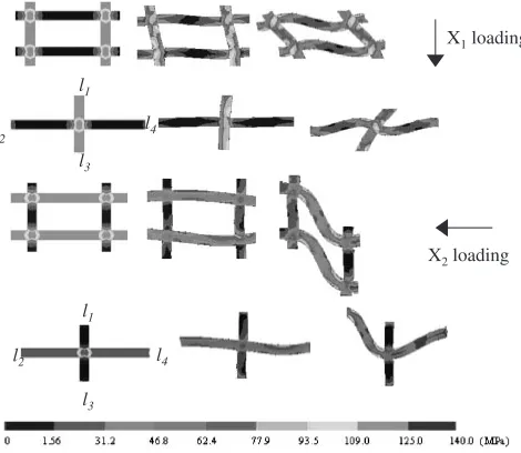
Figure 9 shows stress contour in the cell walls of deformed cells. In the case of loading inX1, diagonal columns ofl3and
l4 only bent in the post-yielding to form a pair of localized
deformation bands in 45 degrees. No significant bending occurs in other four columns ofl1,l2,l5andl6. On the other
hand, in the case of loading inX2, only one column ofl5bent
in collapsing and other columns never collapsed. This leads to formation of a single bent-shear-mode localized deforma-tion band.
For rectangular unit cells, post-yielding behavior is governed by formation of localized deformation bands in the bent-shear collapsing mode. When a rectangular cell-structured material is compressed in the direction along the long columns ofl2andl4, uniform compressive deformation
changes itself to collapsing in bent-shear mode. This local-ization overwhelms other post-yielding deformation modes. On the other hand, when loading along the shorter columns, the whole material deforms in bending without significant
0.0 3.0 6.0 9.0 12.0
0.00 0.05 0.10 0.15 0.20 0.25 0.30
Nominal compressive
stress, MPa
Nominal compressive strain
X2 X1
X1
X2
εc=0.00 εc=0.05 εc=0.10 εc=0.15 εc=0.20 εc=0.25
[image:5.595.50.289.69.267.2]Fig. 8 Nominal compressive stress–strain responses and temporal de-formed configurations of diamond cell-structured materials inX1andX2 directions.
Table 2 In-plane elastic properties of regularly cell-structured honey-combs.12Þ
Relative density, E
1=EsorE2=Es
Square cell 2l=t t=l
Triangle cell 2pffiffiffi3t=l 2t=pffiffiffi3l
Rectangular cell ðhthþltlÞ=hl th=l,tl=h Diamond cell 5t=pffiffiffi3l 2t=p3ffiffiffil,t=pffiffiffi3l
Note:Esis Young’s modulus of solid material.
Table 3 Specific plateau stresses of regularly cell-structured honeycombs.
X1direction (MPa)
X2direction (MPa)
Square cell 25.2 25.2
Triangle cell 25.6 18.9
Rectangular cell 32.4 21.6
Diamond cell 13.6 12.7
Note: the specific plateau stress is calculated by dividing the nominal stress by its relative density.
X1loading
X2loading
l1
l2
l3 l4
l5
l6
[image:5.595.306.549.85.159.2] [image:5.595.306.548.652.758.2] [image:5.595.47.291.711.776.2]localization. Hence, the shorter columns in the rectangular cell bend but have nothing to do with shear localization. As shown in Fig. 10, formation of localized deformation band is driven by collapsing of longer columns in the bent-shear mode. Initial yielding and post-yielding deformation in the early stage are affected by the plastic anisotropy, which comes from different stiffness in the compression direction. Since the localized zone is densified and rest cells support the in-plane compressive load, stress state gradually turns to be isotropic with compression.
The above difference in elasto–plastic compression behav-ior between triangular and rectangular cell-structured mate-rials, is thought to be affected by the column connectivity (N): N¼4 for square and rectangular cells andN¼6 for triangular ones. In the former, the post-yielding deformation is driven by collapsing in the pair of columns in a cell in the bent-shear-mode. Although the macro–stress vs. macro– stress relationship is dependent on the number of localized deformation bands, the above post-yielding deformation mechanism is commonly held on for this type of cells. In the latter, the columns to deform in bent-shear collapsing mode are selected among six connected columns. Since different columns and different pairs of columns have contribution to post-yielding behavior, different macro–stress vs. macro– strain relations are obtained for the cellular materials with a unit cell having N¼6. That is, both the initial and plateau stresses are controlled by the post-yielding deformation mechanism and are designable by connectivity of columns in the unit cell.
Diamond unit cell has a mixed column-connectivity with
N¼4 and 6. Figure 11 depicts typical two deformation modes. At the initial yielding, uniform compressive defor-mation changes to plastic buckling in bending of a single column along the loading direction in theX2direction. This deformation mode develops to form a localized deformation band in the bent-shear collapsing mode in cooperation with the bending of cell columns whenN¼4. This leads to severe localization in the skewed angle of 60to theX
1-axis. For the
X1-loading, uniform compressive deformation changes to plastic bending in the case of four column-connectivity. No distortion occurs in the diagonal columns of l2 and l5.
Therefore, a set of columns is selected among six in the unit cell to make buckling and bending deformation in the dependent manner on the loading directions. Hence, initial yielding stress is dependent on the stiffness of first bucking column. Once the shear localization advances in the bent-shear collapsing, the plateau stress becomes insensitive to collapsing deformation for sub-unit cells.
6. Conclusion
Uniform compression in plane–strain condition of regu-larly cell-structured materials has been simulated theoret-ically through the finite element analysis. Compressive response of cellular materials is described by deformation mode change. In a perfect symmetric deformation, uniform compression mode advances until densification. In this case, there is no plastic anisotropy. In general cellular materials, the deformation mode changes itself from uniform compres-sion to shear localization mode. This plastic behavior depends on the cell geometric topology. When the cellular materials are composed of unit cells with four-column connectivity, initial yielding is determined by bending of the longest column along the compression direction and post-yielding is controlled by localized collapsing deformation in the bent-shear mode. In the case of six-column connected cellular materials, the columns to be collapsing are selected among six columns so that the whole materials elasto-plastically deform with different types of shear localizations. The above different plastic nonlinearity of six-column cell drives plastic anisotropy in this type of cellular materials. This implies that mechanical properties of cell-structured materials are quantitatively predicted by rational elasto– plastic theory with consideration of unit and sub-unit cells.
REFERENCES
1) J. David Sypeak and N. G. Wadley Haydn: Adv. Eng. Mater.4(2002) l4
l1
l2
X1loading
X2loading
l1
l2
[image:6.595.51.286.73.277.2]l3 l4 l3
Fig. 10 Stress contours and shear localization develop in the square cell-structured honeycomb.
X1loading
X2loading
l1
l2 l3 l4
l5 l6
[image:6.595.300.546.74.259.2]759–764.
2) L. David Krause, D. John Whittenberger, T. Pete Kantzos and G. Mohan Hebsur: Proc. Properties of Lightweight Cellular Metals and Structures, (Proceedings of the 2002 TMS Annual Meeting in Seattle, Washington, 2002) pp. 233–242.
3) Joe K. Cochran, K. J. Lee, D. McDowell and T. Sanders: Proc. Properties of Lightweight Cellular Metals and Structures, (2002) pp. 127–136.
4) David J. Sypeck and Haydn N. G. Wadley: Adv. Eng. Mater.4(2002) 759–764.
5) H. Kanahashi: Ph. D. Thesis, Dynamic Deformation Behavior of Ultra Lightweight Materials with Unit-Cell Structure, March, 2003. 6) Haydn N. G. Wadley, Norman A. Fleck and Anthony G. Evans:
Compos. Sci. Technol.63(2003) 2331–2343.
7) Alethea M. Hayes, Aijun Wang, Benjamin M. Dempsey and David L. McDowel: Mech. Mater.36(2004) 691–713.
8) L. J. Gibson and M. F. Ashby: Celular solids structure and properties,
2nd ed., Cambridge university press, 1997.
9) Russell C. Hibbeler: Mech. Mater., 6th ed., Prentice Hall, New Jersey, 2002.
10) Justin L. Clark, Joe K. Cochran, Thomas H. Sanders and Kon J. Lee: Proc. Properties of Lightweight Cellular Metals and Structures, (2002) pp. 137–146.
11) K. Tantikom: Ph.D. Thesis, Design and Processing of Regularly Cell-Structured Materials, September, 2004.
12) A. J. Wang and D. L. McDowell: J. Eng. Mater. Tech.126(2004) 137– 156.
13) K. Tantikom, Y. Suwa and T. Aizawa: Mater. Trans.45(2004) 509– 515.
14) K. Tantikom, T. Aizawa and T. Mukai: Int. J. Solids Struct.42(2005) 2199–2210.