OFDM systems design using harmonic wavelets
ANOH, Kelvin, IKPEHAI, Augustine, ADEBISI, Bamidele, RABIE, Khaled,
POPOOLA, Wasiu and GACANIN, Haris
Available from Sheffield Hallam University Research Archive (SHURA) at:
http://shura.shu.ac.uk/24595/
This document is the author deposited version. You are advised to consult the
publisher's version if you wish to cite from it.
Published version
ANOH, Kelvin, IKPEHAI, Augustine, ADEBISI, Bamidele, RABIE, Khaled,
POPOOLA, Wasiu and GACANIN, Haris (2019). OFDM systems design using
harmonic wavelets. 2019 IEEE Wireless Communications and Networking
Conference (WCNC).
Copyright and re-use policy
See
http://shura.shu.ac.uk/information.html
Sheffield Hallam University Research Archive
†School of Engineering, Manchester Metropolitan University, Manchester, M1 5GD, UK
‡Institute for Digital Communications, School of Engineering, University of Edinburgh, Edinburgh EH9 3JL, UK §Nokia-Bell Labs Antwerp, Belgium
†[k.anoh, a.ikpehai, b.adebisi, k.rabie]@mmu.ac.uk,‡[email protected], §[email protected]
Abstract—Orthogonal frequency-division multiplexing
(OFDM) is a popular multi-carrier technique used in many digital communication systems such as wireless fidelity (Wi-Fi), long term evolution (LTE) and power line communication systems. It can be designed using fast Fourier transform (FFT) or wavelet transform (WT). The major drawback in using WT is that it is computationally inefficient. In this study, we introduce a simple and computationally efficient WT, harmonic wavelet transform, for OFDM signal processing. The new WT uses the orthogonal basis functions of conventional FFT-OFDM except that it involves translation and dilation of the input signal; the new wavelets is referred to as harmonic wavelets (HW). When compared with pilot-assisted OFDM system in terms of reduction in the peak-to-average power ratio, the results show that HW-OFDM outperforms FFT-OFDM by 3 dB at 10−4 CCDF (complementary cumulative distribution function). Over Rayleigh fading channel with additive white Gaussian noise (AWGN), the bit error ratio of both FFT-OFDM and HW-OFDM perfectly matched, showing that the proposed HW-OFDM is better in terms of peak-to-average power ratio reduction.
Index Terms—BER, Harmonic wavelet, OFDM, PAPR,
pilot-assisted OFDM, Rayleigh fading, Wavelet.
I. INTRODUCTION
The study of orthogonal frequency-division multiplexing (OFDM) design using discrete Fourier transform (DFT) has been around for some time [1]. OFDM is prominent in the design of communication systems such as Wi-Fi, WiMAX, LTE and power line communication (PLC) systems. It divides wide bandwidth into many narrow bands leading to long symbol periods in time-domain and making OFDM robust against multipath fading. OFDM can be implemented using fast Fourier transform (FFT) which is the computationally efficient algorithm of DFT [2]. The FFT reduces computational complexity fromO!
N2
toO(Nlog2N)forNdata symbols.
However, one of the major drawbacks of OFDM design using FFT is that it suffers from high peak-to-average power ratio (PAPR). In other words, conventional communication systems operating with FFT-OFDM leads to inefficient and costly high power amplifier (HPA). This is the major reason for not using OFDM in the uplink of mobile communication standard [3]. To solve this problem, there are different alter-natives reported in the literature including single-carrier (SC) frequency-division multiple access (FDMA), fractional Fourier transform (FrFT) and wavelet transform (WT) [4]–[7]. While SC-FDMA demonstrates improved PAPR performance, FrFT and WT are computationally burdensome which may lead to
slow performing and high power consuming systems. One of the reasons why FrFT and WT may have not appeared in the wireless communication systems includes that such systems are power-limited and may cause high power consumption problems. WT is used in designing OFDM system and has better spectral leakage than filtered-OFDM as in IEEE 1901 standard commonly applied in PLC systems [8].
In this study, we present a new implementation scheme of WT that uses FFT/IFFT, initially described as harmonic wavelets (HW) [9]. HW was originally proposed to study the vibration of advanced rotating machines in mechanical vibra-tions and rotordynamics [10]. The main advantage of using wavelets in machine condition monitoring is that wavelet maps can produce three-dimensional (3D) plots showing amplitude, frequency and time [10]. FFT on the other hand only shows frequency (or time) and amplitude (or 2D). Wavelets show tiny changes in the frequency domain that cannot be detected in the conventional (FFT-based) frequency spectrum.
Since the HW can be implemented using the IFFT/FFT al-gorithm, the system model enjoysO(Nlog2N)computational
efficiency for them= log2(N)decomposition levels involved
in the processing of N-long input symbol using WT. Given these advantages, we extend the new wavelet transform (i.e. HW) into the design and study of communication systems driven by OFDM and this will be referred to as HW-OFDM. In particular, this study will investigate the PAPR performance of the HW-OFDM system against that of FFT-OFDM for pilot-assisted OFDM (PA-OFDM) system. Alongside, the bit error ratio (BER) performance over Rayleigh fading channel with additive white Gaussian noise (AWGN) will be reported. Our results highlight that HW-OFDM system achieves similar BER performance with FFT-OFDM system over fading channel with AWGN. On top of that, HW-OFDM systems exhibits better reduced PAPR, up to 3 dB, than the OFDM scheme.
II. SYSTEMMODEL
Consider a signal x[n],∀n= 0,· · ·, N−1in time domain, its frequency domain contentsX[k],∀k= 0,· · ·, N−1can be realized from the FFT transform ofx, wherenandkrepresent the time and frequency domains indices, respectively. The time domain OFDM signal can then be expressed as
x[n] = √1
N
N−1 X
k=0
X[k] exp
i2πkn N
,∀n, k= 0,· · ·, N−1
2
-8 -6 -4 -2 0 2 4 6 8
-Nπ≤ x ≤Nπ -1
-0.8 -0.6 -0.4 -0.2 0 0.2 0.4 0.6 0.8 1
Real
ψ
[image:3.595.59.272.98.268.2](x)
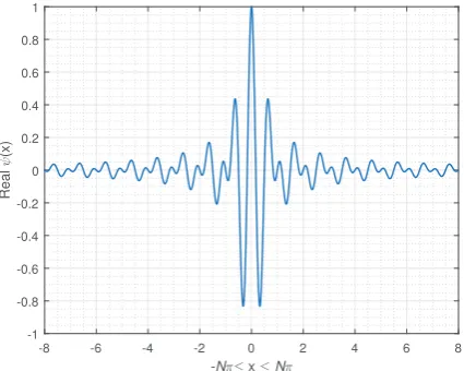
Figure 1: Real part of HW transform of a signal
where i = √−1 and (1) is the conventional FFT-OFDM. Unlike DFT, WT is an alternative design kernel for imple-menting OFDM-like multicarrier systems. WT are made up of low-pass filters (LPF) and high-pass filters (HPF) that weight the dilated scaling function, φ. The LPF is related to the scaling function and both are used to realize the approximate coefficients aof the signal while the HPF is concerned with the wavelet function,ψ, both of which are used to extract the detail coefficientsdof the signal.
A. OFDM Systems Design using WT
Given the time domain signal x[n],∀n = 0,· · ·, N −1
and 2m ∈ N, the WT of x[n] are the dilated (’stretched’)
and translated (’repositioned’) versions of x[n]. When only the approximate coefficient is dilated, only the discrete WT (DWT) are realized. On the other hand, when both the detail and approximate coefficients of x[n] are dilated at every decomposition level, m, the wavelet packet transform (WPT) are realized. A comparative study on the performance of DWT and WPT for OFDM systems has been documented in [11]. Besides, the implementation of WPT-OFDM for multi-antenna application has also been discussed in [12].
The aim of this study is to design an OFDM system using a different kernel other than FFT/IFFT. The alternative kernel uses the DFT tool except that there exists dilation (stretching) and translation (repositioning) of the signal coefficients. Since WT finds applications in communication systems design, WT-OFDM has been studied by different authors for wireless [13]–[16] and PLC [17], [18] systems. A major drawback in its adoption is that it is computationally inefficient and recent studies have led to different computationally efficient algorithms such as the ones reported in [9] and [19]. In the following, the basics of OFDM system design using WT as an alternative kernel to FFT are discussed.
B. Wavelet and Scaling Functions of HW Transform
From Section II-A, it is observed that there are two essential parts of a WT, namely the scaling function φ(·) and the
-8 -6 -4 -2 0 2 4 6 8
-Nπ≤ x ≤Nπ -1
-0.8 -0.6 -0.4 -0.2 0 0.2 0.4 0.6 0.8 1
Imaginary
ψ
[image:3.595.313.528.98.268.2](x)
Figure 2: Imaginary part of HW transform of a signal
wavelet functionψ(·). HW transform also has these important parts and will be required in the processing of the signal. Meanwhile, the advantages of HW are that it is simple and fast to compute [10]. HW is known to be faster than other WTs and up to four times faster than Daubechies wavelets [10]. These properties make HW attractive in many applications that require low complexity and low computational cost.
The wavelet function of HW was derived in [9] as
ψ(x) =exp(i4πx)−exp(i2πx)
i2πx , −π≤x≤π. (2) By observing (2) closely, one can easily separate the compo-nents ofψ into real and imaginary parts as follows
ψ(x) =ψe(x) +iψo(x), (3)
which is generally a complex number. Pictorially,ψe(x)and
ψo(x)can be illustrated as shown in Figs. 1 and 2, respectively.
It can be observed that the HW concentrates the energy of the signal (compact) around zero.
Recall that WT uses dilation and translations of signals. By replacingxin (2) with(2mx−t), the HW transform stretches
x byt at eachmth decomposition level. The implication of
(2mx−t)is that the scale of HW is compressed by the factor
2m while its position is translated (repositioned) by t time
units during every new scale. Similar to (3), the translated and dilated versions of (2) have a complex conjugateψ¯(2mx−t)
given in terms of Fourier transform [20] as
¯
ψ(2mx−t) = 1 2π
Z 4π2m 2π2m
1
2mexp(iωt/2
m) exp(−iωx)dω
(4)
Both ψ¯(2mx−t) and ψ(2mx−t) are required in the
real-ization of the detail coefficients ofx.
-8 -6 -4 -2 0 2 4 6 8 -Nπ≤ x ≤Nπ
-0.4 -0.2 0 0.2 0.4 0.6 0.8 1
Real
φ
[image:4.595.313.527.96.267.2](x)
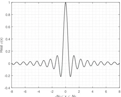
Figure 3: Real part ofφ(x)of HW transform of a signal
multi-resolution analyses of a signal using wavelet theory. The scaling function can be expressed as follows [9]
φ(x) = exp(i2πx)−1
i2πx , −π≤x≤π. (5)
Its translated version is realized from substituting x with
(x−t). Similar to (3), the scaling function can be decomposed into real and imaginary parts as follows
φ(x) =φe(x) +iφo(x), (6)
whereφe(x)andφo(x), respectively are shown in Figs. 3 and
4. Similar to the case of the ψ(·), it can as well be noticed that the energy of the transformed signal using the φ(·) is concentrated around zero (i.e. compact). In the study of HW, the scaling function φ(x−t) and its conjugateφ¯(x−t)as well as the wavelet functionψ(2mx−t)and its corresponding
conjugateψ¯(2mx−t)are required in the signal analyses. The
decomposition and stretching lead to subchannelization. Recall that the PAPR of OFDM signal, decreases with decreasing FFT sizes. In other words, due to the subchannelization, the peak power of sub-band signals at each decomposition level will be lower than the conventional; in general, this will cause HW-OFDM to exhibit lower PAPR than FFT-OFDM.
C. Orthogonality
In designing OFDM systems, the basis functions must satisfy the condition of orthogonality. HW of different (m)
decomposition levels are orthogonal; mathematically,
Z ∞
−∞
ψ(x) ¯ψ(2mx−t)dx= 0 (7)
where ψ¯(·) represents the complex conjugate of ψ(·). In addition, ∀t6= 0, all wavelets translated by any integert unit are orthogonal to each other. These are already proven in [9].
-8 -6 -4 -2 0 2 4 6 8
-Nπ≤ x ≤ Nπ
-0.8 -0.6 -0.4 -0.2 0 0.2 0.4 0.6 0.8
Imaginary
φ
(x)
Figure 4: Imaginary part ofφ(x)of HW transform of a signal
D. OFDM Signal from WT
In the analyses of HW, both φ(·) and ψ(·) are usually considered; including their corresponding conjugates. This involves combining the results in (4) and (6) to process the signal,x. In that case, the output signal can be expressed as
f(x) =
∞
X
t=−∞
x(φ,t)φ(x−t) + ¯x(φ,t)φ¯(x−t) +
∞
X
m=0
∞
X
t=−∞
x(ψ,t)ψ(2mx−t) + ¯x(ψ,t)ψ¯(2mx−t) , (8)
where x(ψ,t) is associated withψ(·)as follows [20]
x(ψ,t)= 2m
Z ∞
−∞
f(x) ¯ψ(2mx−t)dx
= 2m
−1 X
v=0
X(2m
+v)exp
i2πvt
2m
∀t= 0,1,· · ·,2m−1.
(9)
Clearly, (9) is the inverse Fourier transform ofX(2m+v)which
can be implemented using IFFT. Similarly, the amplitude of the corresponding complex conjugate of the wavelet can be written as
¯
x(ψ,t)= 2m
Z ∞
−∞
f(x)ψ(2mx−t)dx
= 2m
−1 X
v=0
X−(2m
+v)exp
−i22πvtm
. (10)
By using the circular property of DFT, it can be remarked that
X(−v)=X(N−v), ∀v= 0,1,· · ·,2m−1. (11)
Based on (11), we can rewrite (10) as follows
¯
x(ψ,t)= 2m
−1 X
v=0
XN−(2m+v)exp
−i22πvtm
[image:4.595.59.272.97.267.2]
4
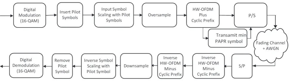
Figure 5: Block diagram for implementing HW-OFDM (P/S: parallel to serial conversion and S/P: serial to parallel conversion).
The approximate coefficients, namelyx(φ,t) andx¯(φ,t) are
obtained from φ¯(·) and its complex conjugate φ(·), respec-tively. From the foregoing discussion,
x(φ,t)= 2m
Z ∞
−∞
f(x) ¯φ(x−t)dx
= Z 2π
0
X(ω) exp(iωt)dω, (13)
where X(ω) =R∞
−∞f(x)e
−iωxdωand the scaling function is
φ(x−k) =
Z ∞
−∞
Φ(ω)e−iωkeiωxdx. (14)
Note thatΦ(ω) = 0except for0≤ω <2π. By lettingX(ω= 0)be replaced withX0,x(φ,t)=X0/2 andx¯(φ,t)=X0/2so
that
x0=x(φ,t)+ ¯x(φ,t)=X0. (15)
Lastly, to ensure that Parseval’s theorem holds i.e.,
1 2m
P2m−1
t=0 |x2m+t|2=
P2m−1
t=0 |X2m+t|2, we set
xN/2=XN/2. (16)
In summary, we require only (9), (12), (15) and (16) to imple-ment the HW transform in OFDM design. Useful MATLAB codes that implement HW transform can be found in [20].
E. Pilot-Assisted OFDM from HW-OFDM Symbol
PAPR reduction in OFDM systems is an important tool for increasing the power efficiency of HPA in digital communica-tion systems. OFDM symbols exhibit high peaks which may appear within the nonlinear region of operation of HPAs. By reducing these peaks to reside within the linear region, HPA consume less power. There are different techniques in the liter-ature for reducing the PAPR performance of OFDM systems. Examples include clipping [21], [22], companding [23], [24] and use of pilot symbols [18], [25]. In this study, pilot symbols scheme applied to reduce the PAPR in wavelet-OFDM system in [18] is adopted. By using pilot symbols, no additional over-head is introduced to the system since the pilot-symbols are used also for channel estimation purposes [25]. The system model is shown in Fig. 5. Consider some frequency domain
symbols,Dn¯ and some pilot symbols Muτ =Aτ,uexp (iθτ,u),
we express the modified symbol as
¯
X¯n=Dn¯⊗Muτ ∀τ ∈P,¯n∈N−P, (17)
whereAu
τ,∀u= 1,· · ·, U is the amplitude of Muτ with phase
θτ,u,∀¯n= 0,1,· · ·, N−P andX¯n¯∈C(N−P)×1. In (17), the
amplitudes of the pilot symbol,Aτ,u, scale the amplitudes of
frequency domain content of the HW-OFDM signal while the phase of the frequency domain content of the HW-OFDM is rotated byθτ,uwhich are drawn fromθτ,u= [0, π]. After that,
the pilot symbols which can be used for channel estimation are inserted as follows [26]
Xj= ¯Xn¯+ ¯Xup,j, ∀j= 0,1,· · ·, N−1, (18)
where P is the number of pilots and u ∈ U is the pilot sequence. After these, the HW-OFDM pilot-aided symbol is oversampled by a factorℓ to ensure that none of the symbol peaks is missed out, such that
Xn= [Xj 01×ℓN−N] ∀n= 0,1,· · ·, ℓN−1. (19)
The HW-OFDM that will be transmitted over the channel which includes pilot symbols and oversampling can be ex-pressed as
s[n] =W(Xn) ∀n= 0,1,· · ·, ℓN−1, (20)
whereW(·)is the HW transform of the input symbol which
is expressed in (8). Next, the signal that achieves the minimum PAPR amongr= 1,2,· · ·,r¯iterations from the following
¯
sup,r[n] = min1≤r≤r¯
!
PAPRup,r ∀u= 1,· · ·, U (21)
will be transmitted over the fading channel. In (21), the PAPR of the pilot-assisted HW-OFDM signal can be determined as
PAPRup,r= maxn=0,···,ℓN−1
|¯su p,r[n]|2
E
|s¯u p,r[n]|2
, (22)
whereE{·}is the expected value operator. Usually, the PAPR is reported in terms of CCDF and can be expressed as
Pr{PAPR>PAPR0}=
1− {1−exp (−PAPR)}ℓN
, (23)
where Pr{·}represents the probability of{·}.
6 7 8 9 10 11 12 13 PAPR0 (dB)
10-4 10-3 10-2 10-1 10
CCDF(Pr
(PAPR>PAPR
0
))
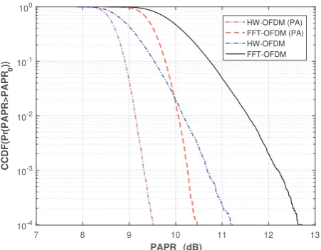
[image:6.595.56.285.96.275.2]HW-OFDM (PA) FFT-OFDM (PA) HW-OFDM FFT-OFDM
Figure 6: PAPR performance of pilot-assisted HW-OFDM in comparison with FFT-OFDM (ℓ= 4, 16QAM and N = 128)
7 8 9 10 11 12 13
PAPR 0 (dB) 10-4
10-3 10-2 10-1 100
CCDF(Pr
(PAPR>PAPR
0
))
HW-OFDM (PA) FFT-OFDM (PA) HW-OFDM FFT-OFDM
Figure 7: PAPR performance of pilot-assisted HW-OFDM in comparison with FFT-OFDM (ℓ= 4, 16QAM andN = 1024)
that the fading channel follows the Rayleigh distributions with variance σ2
h. The received signal in frequency domain after
the cyclic prefix is removed can be expressed as:Y =HX+ Z where H is the channel transfer function and X is the transmitted signal. The recovered signal after equalization can be written as
¯
X =HM M SE·Y =X+
H⋆
|H⋆|2+Ex
N0
−1Z, (24)
where Z ∼ N(0, σ2
z) is the AWGN and HM M SE is the
minimum mean square error (MMSE) channel equalizer given
by H⋆/
|H⋆|2+Es
N0 −1
. (24) is the MMSE estimate of
the transmitted OFDM symbol. MMSE equalization is used because it has the potential to minimize the impact of noise on the received signal.
0 5 10 15 20 25 30 35 Eb/N0 (dB)
10-5 10-4 10-3 10-2 10-1 10
Bit Error Ratio
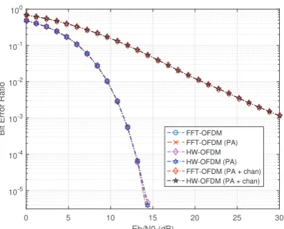
[image:6.595.314.539.96.277.2]FFT-OFDM FFT-OFDM (PA) HW-OFDM HW-OFDM (PA) FFT-OFDM (PA + chan) HW-OFDM (PA + chan)
Figure 8: BER performance of HW-OFDM in comparison with FFT-OFDM over a Rayleigh fading channel with AWGN (ℓ= 4,M = 16 QAM andN=128)
III. SIMULATIONRESULTS ANDDISCUSSION
To demonstrate the performance of the proposed HW-OFDM relative to FFT-HW-OFDM, we conducted an investigation using the model shown in Fig. 5. The model used in the simulation involvesN= 128 randomly generated input sym-bol which are digitally modulated using16-QAM (quadrature amplitude modulation). Signals realized from this process were scaled to ensure thatE{|s[n]|} ≈1. Afterwards, pilot symbols with property as discussed in Section II-E are constructed and inserted within the HW-OFDM symbol before transmission over the channel. The PAPR of the output symbols is estimated using (22). As shown in Fig. 5, only the HW-OFDM symbol with the minimum PAPR value among r = 1,· · ·,r¯ are transmitted over the channel. The fading channel assumes the Rayleigh distribution in which the channel state information are known at the receiver. At the receiver, we adopted MMSE equalization technique to recover the transmitted signals as shown in (24). These processes are repeated for N = 1024
and the results obtained over the Rayleigh fading channel with AWGN are reported in terms of BER in Figs. 8 and 9.
We find in Fig. 6 that the PAPR performance of HW-OFDM is lower than that of standard FFT-HW-OFDM system by about 0.5 dB. When the phase and amplitudes (Au
i = 1) of
the pilot symbols are exploited, this PAPR reduction further improves by an additional 2.5 dB at10−4 CCDF.
Fundamen-tally, increasing the number of OFDM sub-carriers increases PAPR degradation as also seen when comparing Figs. 6 and 7. However, by increasing the number of sub-carriers from
N = 128to N = 1024 for the two schemes, it is seen that
the proposed HW-OFDM further reduces the PAPR by 3 dB at
10−4CCDF relative to FFT-OFDM. Due to varying number of
[image:6.595.55.281.334.510.2]6
0 5 10 15 20 25 30
Eb/N0 (dB)
10-5
10-4
10-3
10-2
10-1
100
Bit Error Ratio FFT-OFDM
[image:7.595.63.269.94.260.2]FFT-OFDM (PA) HW-OFDM HW-OFDM (PA) FFT-OFDM (PA + chan) HW-OFDM (PA + chan)
Figure 9: BER performance of HW-OFDM in comparison with FFT-OFDM over a Rayleigh fading channel with AWGN (ℓ= 4,M = 16 QAM andN=1024)
In terms of BER performance, the FFT-OFDM and the HW-OFDM are seen to perform similarly at all Eb/N0 shown. Typically, PAPR reduction that uses symbol phase rotation has negligible impacts on the BER performance. We can see that although the proposed pilot-assisted scheme reduces the PAPR, it does not degrade the BER performances of the FFT-OFDM and HW-OFDM systems. However, as shown in Figs. 8 and 9, the results show that the BER performance is degraded when compared to the AWGN-only channel; this is expected due to the impacts of the dispersive channel on the OFDM symbols and the noise that is magnified due to channel estimation. One of the ways of improving this performance is through forward error correction.
IV. CONCLUSION
In this study, we have demonstrated a new WT de-sign scheme for processing OFDM symbols. The HW was implemented using the FFT/IFFT algorithm (that requires
O(Nlog2N)hence computationally efficient) and uses only
m = log2(N) decomposition levels given a data symbol
of length N. The design kernel is the HW and was found to exhibit 3dB better in PAPR performance than FFT-based OFDM. Over Rayleigh fading channels, we observed that the model performs similarly as the FFT-based OFDM in terms of BER. Since the HW-OFDM has equivalent BER performance as the FFT-OFDM and uses the FFT/IFFT tool, the HW-OFDM scheme can be applied in the design of communication systems henceforth; both wireless and wired. In the future, we shall assess the performance of the proposed kernel with other alternative design kernels for OFDM systems.
REFERENCES
[1] S. Weinstein and P. Ebert, “Data Transmission by Frequency-Division Multiplexing Using the Discrete Fourier Transform,”IEEE Trans. Com-mun. Technol., vol. 19, no. 5, pp. 628–634, Oct. 1971.
[2] R. N. Bracewell,The Fourier transform and its applications. McGraw-Hill New York, 1986, vol. 31999.
[3] G. Wunder, R. F. H. Fischer, H. Boche, S. Litsyn, and J.-S. No, “The PAPR problem in OFDM transmission: New directions for a long-lasting problem,”IEEE Signal Process. Mag., vol. 30, no. 6, pp. 130–144, 2013. [4] D. Mendlovic, Z. Zalevsky, and D. e. a. Mas, “Fractional wavelet
transform,”Applied optics, vol. 36, no. 20, pp. 4801–4806, 1997. [5] J. Shi, N. Zhang, and X. Liu, “A novel fractional wavelet transform
and its applications,”Science China Info. Sciences, vol. 55, no. 6, pp. 1270–1279, 2012.
[6] M. Martone, “A multicarrier system based on the fractional fourier trans-form for time-frequency-selective channels,” IEEE Trans. Commun., vol. 49, no. 6, pp. 1011–1020, Jun. 2001.
[7] K. O. O. Anoh, R. A. A. Alhameed, and S. M. R. Jones, “An investigation of FrFT modulation and FFT-OFDM for multiple input multiple output application,” in14th Annual Post Graduate Symposium on Convergence of Telecom., Network. Broadcast., 2013.
[8] A. Farhang, M. M. Kakhki, and B. Farhang-Boroujeny, “Wavelet-OFDM versus filtered-OFDM in power line communication systems,” in2010 5th Intl. Symposium Telecom., Dec. 2010, pp. 691–694.
[9] D. E. Newland, “Harmonic wavelet analysis,”Proc. R. Soc. Lond. A, vol. 443, no. 1917, pp. 203–225, 1993.
[10] J. I. Bonel-Cerdan and J. L. Nikolajsen, “An introduction to harmonic wavelet analysis of machine vibrations,” in ASME 1997 Intl. Gas Turbine and Aeroengine Congress and Exhibition. American Society of Mechanical Engineers, 1997, pp. V004T14A011–V004T14A011. [11] O. O. Anoh, N. T. Ali, R. Abd-Alhameed, S. M. R. Jones, and
Y. A. S. Dama, “On the performance of DWT and WPT modulation for multicarrier systems,” in2012 IEEE 17th Intl. Workshop on Computer Aided Modeling and Design of Commun. Links and Networks (CAMAD), Sept. 2012, pp. 348–352.
[12] K. O. O. Anoh, R. A. Abd-Alhameed, J. M. Noras, and S. M. R. Jones, “Wavelet packet transform modulation for multiple input multiple output applications,”Intl. J. Computer Appl., vol. 63, no. 7, pp. 46–51, 2013. [13] M. K. Lakshmanan and H. Nikookar, “A review of wavelets for digital
wireless commun,”WPC, vol. 37, no. 3-4, pp. 387–420, 2006. [14] K. O. O. Anoh, J. M. Noras, R. A. Abd-Alhameed, S. M. R. Jones, and
K. N. Voudouris, “A new approach for designing orthogonal wavelets for multicarrier applications,”AEU-Intl. J. Electron. Commun., vol. 68, no. 7, pp. 616–622, 2014.
[15] K. O. O. Anoh, T. T. Mapoka, R. A. Abd-Alhameed, O. Ochonogor, and S. M. R. Jones, “On the application of raised-cosine wavelets for multicarrier systems design,” Intl. J. Commun. and Propagation (IRECAP), vol. 4, no. 4, pp. 143–150, Aug. 2014.
[16] K. O. O. Anoh, R. A. Abd-Alhameed, O. Ochonogor, Y. A. S. Dama, S. M. R. Jones, and T. T. Mapoka, “Performance evaluation of raised-cosine wavelet for multicarrier applications,” Intl. J. Environmental Engineering, vol. 1, no. 3, pp. 1–5, Sept. 2014.
[17] S. Galli, H. Koga, and N. Kodama, “Advanced signal processing for plcs: Wavelet-OFDM,” inIEEE ISPLC 2008, 2008, pp. 187–192. [18] K. Anoh, A. Ikpehai, K. Rabie, B. Adebisi, and W. Popoola, “PAPR
reduction of wavelet-OFDM systems using pilot symbols,” in2018 IEEE ISPLC, Apr. 2018, pp. 1–6.
[19] S. G. Mallat, “A theory for multiresolution signal decomposition: the wavelet representation,” IEEE Trans. Pattern Analysis and Machine Intelligence, vol. 11, no. 7, pp. 674–693, 1989.
[20] D. E. Newland,An introduction to random vibrations, spectral & wavelet analysis. Courier Corporation, 2012.
[21] X. Li and L. J. Cimini, “Effects of clipping and filtering on the perfor-mance of OFDM,” in1997 IEEE 47th Veh. Technol. Conf.. Technol. in Motion, vol. 3, May 1997, pp. 1634–1638 vol.3.
[22] K. Anoh, C. Tanriover, B. Adebisi, and M. Hammoudeh, “A new approach to iterative clipping and filtering PAPR reduction scheme for OFDM systems,”IEEE Access, vol. 6, pp. 17 533–17 544, Sept. 2018. [23] B. Adebisi, K. Anoh, and K. M. Rabie, “Enhanced nonlinear
compand-ing scheme for reduccompand-ing PAPR of OFDM systems,”IEEE Systems J., vol. PP, no. 99, pp. 1–11, Jul. 2018.
[24] B. Adebisi, K. Anoh, K. M. Rabie, A. Ikpehai, M. Fernando, and A. Wells, “A new approach to peak threshold estimation for impulsive noise reduction over power line fading channels,”IEEE Systems J., vol. PP, no. 99, pp. 1–12, Mar. 2018.
[25] W. O. Popoola, Z. Ghassemlooy, and B. G. Stewart, “Pilot-assisted PAPR reduction technique for optical OFDM communication systems,” J. Lightwave Technol., vol. 32, no. 7, pp. 1374–1382, Apr. 2014. [26] K. Wesołowski, “On the PAPR minimization using selected mapping