Abstract—A novel idea of using giant magnetostrictive material (GMM) based actuators for journal bearing control is presented in this paper. Frequency response tests on GMM actuators and a journal bearing system were examined. The performances of the system running at various journal shaft rotational speeds under control were investigated. With the aid of GMM actuators, the performances on journal shaft positioning and vibration suppression were enhanced with the hydrodynamic effect of the oil film force inside the bearing. The results demonstrate that the novel concept is feasible and also show that GMM is an excellent material for driving function.
Index Terms—Giant magnetostrictive material, Frequency response, Journal bearing, Active vibration control
I. INTRODUCTION
Journal bearings are vital mechanical elements commonly used in rotary machinery, which have longer serving life and higher loading capacity than rolling bearings under long-term and heavy duty conditions. However, the main drawbacks of journal bearings are low accuracy of positioning and stability during high-speed rotation, which limit their high-speed and high precision applications. Since long service life and high loading capacity are essential for most rotary units, the applications of journal bearing can be extended if there are improvements in positioning accuracy and stability. To obtain the benefits of using hydrodynamic journal bearing but without forsaking the positioning and stability requirements, one can make use of active elements which should have the characteristics of easy to control, fast response, high accuracy, high dynamic force, and large control range of the same order of magnitude as the clearance between the journal shaft and the bearing ring.
Active vibration control of rotor-bearing system has aroused great interest in the world for years. Being an important engineering problem, vibration suppression on rotating machinery has been achieved through various types of control techniques and vibration damping devices. Active magnetic bearing under adaptive autocentering control [1] with efficient contact prevention strategy [2], active hydraulic bearing with adaptive control algorithm [3], active tilting-pad bearing [4], [5], active vibration control with piezoceramics [6]-[9] were utilized to reduce rotor vibration through active
Manuscript received on March 30, 2009. The work was fully supported by a grant provided by City University of Hong Kong SRG 7002238.
H. Y. Lau, K. P. Liu, and P. L. Wong are with Department of Manufacturing Engineering and Engineering Management, City University of Hong Kong, Kowloon, Hong Kong (e-mail: [email protected]; [email protected]; [email protected] )
W. Wang is with School of Mechatronics and Automation, Shanghai University, Shanghai, China (e-mail: [email protected] )
damping, adjustment of load stiffness, enhancement of rotor balancing capability, and compensation for misalignment during rotor operations. However, these active bearings can suffer from the problems of low loading capacity, complex, continuous high power consumption, small range of control, slow response or low accuracy when being used for typical journal bearing applications. These aforementioned drawbacks limit their application range.
The concept of using GMM for journal bearing control is new [10]-[11]. GMM is a type of material that can be activated to become longer with a given magnetic field, which is referred to as magnetostrictive effect. The research results of the application of giant magnetostrictive material on structural active vibration suppression were shown to be satisfactory in terms of easy for control, fast response, high accuracy and high dynamic force[12]-[14]. It is an excellent material for driving function. Using GMM for actuation is better than piezoelectric material for higher strain and higher loading capacity [15]. All these properties can overcome the main problems of the piezoelectric material and enhance the positioning control and stability of the journal bearing effectively.
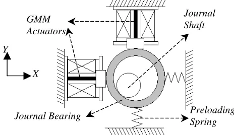
[image:1.595.312.544.624.758.2]II. CONCEPT OF THE NOVEL ACTIVE CONTROL TASK The concept of active-controlled journal bearing by GMM actuators introduced in this paper is shown in Fig. 1. Once the journal shaft oscillates about its center during operation, two orthogonal-placed GMM actuators can be activated to compensate and force the shaft back to its steady-state centre via the oil film through suitable input driving current. It is determined by the feedback signals from the sensors and the system model. Real-time data acquisition and signal monitoring of the system are undertaken as the basis of control. In this way, a complete two-dimensional positioning control of the shaft can be achieved actively and automatically by triggering GMM actuators in order to minimize the eccentric and vibrating problems caused by the rotary shaft.
Fig. 1: Conceptual drawing of active control system for the journal bearing
Feasibility of Using GMM Based Actuators in
Active Control of Journal Bearing System
H. Y. Lau, K. P. Liu,
Member, IAENG
, W. Wang, and P. L. Wong
Preloading Spring Journal Bearing
Journal Shaft GMM
Actuators Y
Fig. 2: Test rig (a) Side view (b) Front view: 1-lathe 2-cooling system 3-GMM actuator 4-oil inlet 5-journal bearing 6-spring set 7-eddy current sensor 8-housing
III. EXPERIMENTAL SETUP
Fig. 2 shows the setup of GMM-bearing test rig for this present work. Two GMM actuators were utilized for respective control of the bearing system in X- and Y-directions. The actuators are identical with 1800 turns of copper coil wiring around the GMM rod which is 10 mm in diameter and 60 mm in length to carry out the magnetostrictive effect. The inner diameter of journal bearing is 30 mm with the clearance of 60 µm and diameter-to-width ratio of 1. The diameter and length of the journal shaft are 30 mm and 400 mm respectively. The shaft was mounted on a lathe which can provide discrete rotational speeds ranging from 100 to 1700 rpm. The GMM-bearing system was monitored and controlled actively by National Instruments DAQ Board with LabVIEW software running on computer.
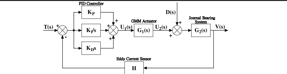
In this work, the implementation of active control on GMM-bearing system was based on PID control algorithm on LabVIEW programming structure. PID algorithm shows its satisfaction on suspension system including for automobiles [16]. The control overview for this work is explained by the block diagram shown in Fig. 3. The reference input T(s) is basically targeted to be zero in order to achieve zero-oscillating amplitude in the system. KP,KIand KD are the three PID controller gain values, where KP can be adjusted automatically in the control algorithm based on the experimental results from frequency response tests on the GMM-bearing system without shaft rotation. KIand KD are determined by trial and error method. G1(s)is the transfer
function of the GMM actuator, which is approximated by a first order system as discussed in the next section. G2(s) is the transfer function describing the dynamic behavior of the journal bearing. It is considered to be complex and believed to be highly non-linear. D(s) is the transfer function representing the external oscillating force due to the shaft eccentricity during rotation. When the shaft is stationary,
) (s
D is zero and the open-loop transfer function is simply represented by G1(s)⋅G2(s). Nevertheless, under operation, the shaft is in rotation and D(s) is non-zero. Due to the non-linearity of G2(s), the overall system is not analyzed from the first principle. As an alternative, the system will be controlled and evaluated through experimental means with the feedback loop. H is the feedback gain constant of the eddy current sensor whose response time is much faster than other mechanical components in the system.
IV. RESULTS AND DISCUSSION
In the experimental part of the work, both static and dynamic performances of GMM actuator were obtained. Besides, the dynamic performance of GMM-bearing system of the open-loop transfer function G1(s)⋅G2(s) was examined and the empirical model was put forward. The proportional gain value KP of the control algorithm was then calculated from the empirical equation, which is related to the journal rotational speed. Finally, the results on active positioning control were demonstrated.
Fig. 3: Block diagram for system control
3
4
5
6
8
2
7
(b) (a)
1
2
G1(s) G2(s)
-+
+ +
T(s) U1(s) U2(s) V(s)
D(s)
KI/s +
KP
KDs
+ +
H
PPPPIIIIDDDD CCCCoooonnnnttttrrrroooolllllllleeeerrrr
G G G
GMMMMMMMM AAccccttttuuuuaaaattttoooorrrrAA JJJJoooouuuurrrrnnnnaaaallll B SSSSyyyysssstttteeeemBBBeeeeaaaarrrriiiinnnnggggmmm
E EE
[image:2.595.61.547.651.777.2]A. Static Performance of GMM Actuator
The GMM actuators were built with a water jacket which permits cooling water to circulate around the GMM rod. The investigation of static and dynamic performances of GMM actuator with minimizing thermal effect was carried out. Fig. 4 indicates an aberrant change in the displacement of the actuator without cooling and the disordered magnetostriction of GMM, which greatly influences the control of GMM. In contrast, the GMM output is stable with the cooling system turned on, which proves the effectiveness of the employed water-cooling system.
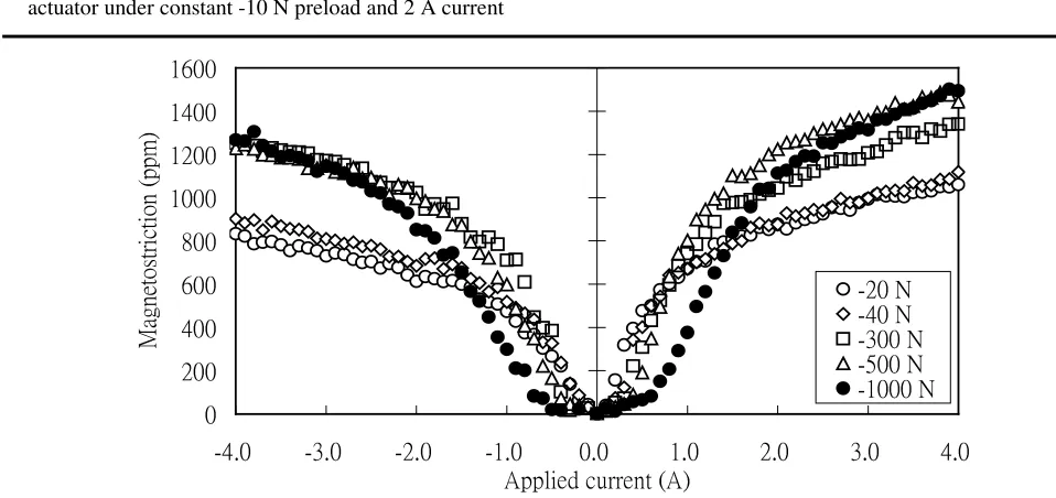
[image:3.595.52.288.371.525.2]The static performance of GMM actuator was tested under a constant compressive force-control mode with a material testing (MTS 810) machine. Fig. 5 illustrates the experimental results of the test corresponding to the supplied current range from 0-4 A in both positive and negative regions under different compressive preloading values. It shows that the saturated magnetostrictive strain can be up to 1400 ppm under the current of 4 A with suitable amounts of preload. Larger the magnitude of the preload, higher the saturated magnetostrictive strain under a given current can be achieved. Fig. 5 shows clearly that under relatively low applied current, the GMM rod of higher preloads requires a higher magnetizing energy to achieve certain levels of magnetostrictive. The same observation was also reported earlier [17]-[19].
Fig. 4: A graph of respective parameters again time for GMM actuator under constant -10 N preload and 2 A current
B. Dynamic Performance of GMM Actuator
It is recognized that one of the important properties of GMM is the generation of positive strain under either positive or negative magnetization (refer to Fig. 5). To achieve two-way actuation, a constant biasing current can be applied. The frequency response of a GMM actuator under a biasing current of 1 A was studied. It can be described as the first order input-output relationship, where the input is the applied alternating current u1(t)to the actuator and the output is the displacement of the actuator u2:
2 2 1
(
t
)
u
u
u
=
τ
&
+
(1)Equation (1) was then transformed into s-domain as the transfer function G1(s) in the concept of control algorithm referring to the block diagram in Fig. 3.
1 1 ) ( 1 + = s s G
τ
(2)Frequency transfer function can be achieved from (2) as the basis of the bode plot.
2 2
1
1
log
20
)
(
ω
τ
ω
+
=
M
(3))
(
tan
)
(
ω
1ωτ
φ
=
−−
(4)where
M
(
ω
)
is the gain in decibel,φ
(
ω
)
is the phase shift in degree,ω
is the driving frequency in radian per second, andτ
is time constant of the model.The value of time constant
τ
can be obtained from the relation with cut-off frequency ωn, which refers to “3 dB drop” from the gain plot:1 = τ
[image:3.595.324.507.476.531.2]ωn (5)
Table I: Measured frequency response of GMM under 1 A biasing current with various preloads
Preloading value (N)
ω
n (rad/s) -250 75.30 -300 55.82 -600 71.38Fig. 5: Measurements of magnetostriction of GMM actuator against applied current under different preloads
-5 0 5 10 15 20 25 30 35 40
0 5 10 15 20 25 30
Time (min) D isp la ce m en t (µ m ) -5 0 5 10 15 20 25 30 35 40 Te m pe ra tu re ( oC) Displacement without cooling
Displacement under cooling Temperature change
0
200
400
600
800
1000
1200
1400
1600
-4.0
-3.0
-2.0
-1.0
0.0
1.0
2.0
3.0
4.0
[image:3.595.48.527.544.770.2]After the experimental tests on GMM actuator, the frequency response of the actuator corresponding to different preloading values can be determined as shown in Table I. It shows that different preloading conditions provide a similar
n
[image:4.595.48.290.157.360.2]ω
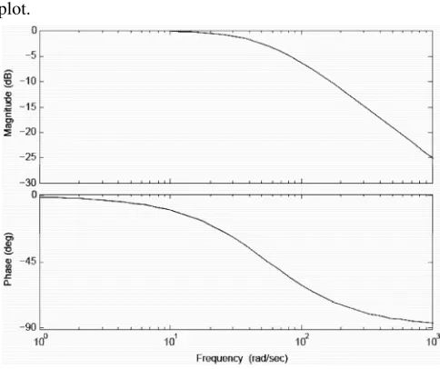
. Fig. 6 shows the bode plot of GMM actuator under -300 N preload. The bode plots for different preloads have been verified and show the agreement with experimental data, especially having the same slope of -20 dB/ decade in the gain plot.Fig. 6: Bode plot of the frequency response for GMM actuator at -300 N preload
C. Dynamic Performance of GMM-bearing System
The experimental results of the open-loop transfer function )
( ) ( 2 1 s G s
G ⋅ for GMM-bearing system are illustrated in Fig. 7. The data of the normalized gain and phase shift between input unit alternating current and output shaft displacement of two actuators were best fitted with empirical models. Two empirical equations of normalized gain G(ω)and phase shift
) (ω
P of the system are respectively expressed as (6) and (7) with the polynomial coefficients shown in Tables II and III:
J I F E C B A
G
ω
=ω
6 +ω
5 +ω
4 +ω
3+ω
2+ω
+ )( (6)
for 0.06 rad/s (0.01 Hz)≤ω≤188.50 rad/s (30 Hz)
W S R Q O N L
P
ω
=ω
6+ω
5+ω
4+ω
3+ω
2+ω
+ )( (7)
for 0.06 rad/s (0.01 Hz)≤ω≤43.98 rad/s (7 Hz)
It is noticed that (6) and (7) are limited to the specified frequency ranges for the reason that undesirable noise appeared in the measurement of the prototype system beyond the range.
Empirical equations (6) and (7) were implemented in the control system as the self-adjusted proportional gain KP for PID control algorithm and phase shift respectively, according to the shaft rotational speed. Since two GMM actuators for X- and Y-directions were identically fabricated, the same empirical models were used for describing the two actuators in the control algorithm.
The results of active positioning control on the journal shaft were demonstrated as the shaft orbit under three different rotational speeds in Figs. 8, 9 and 10. It is noted that all these figures are in the same scale under X- and Y-axes designating the voltage values from the eddy current sensors. The uncontrolled orbits in Figs. 8(a), 9(a) and 10(a) have their original size of about 20 µm. The outcome indicates the remarkable performance on journal shaft vibration suppression by the proposed idea. For the higher speed of 350 rpm, the control performance on shaft becomes more obvious. It is here to point out that the performance of GMM-controlled system was stable under operation with the fluctuation of only about 2 µm, as shown in Figs. 8(b), 9(b) and 10(b).
Fig. 8: Shaft orbit at 100 rpm (a) without control (b) with active control
Fig. 7: Frequency response of open-loop transfer function G1(s)⋅G2(s) for control system (a) Gain plot (b) Phase plot
-5.00 -4.00 -3.00 -2.00 -1.00 0.00
0.10 1.00 10.00 100.00
Driving frequency (rad/s) N
or m al iz ed g ai n (d B)
Experimental data along Y-direction Experimental data along X-direction Empirical fitting in Y-direction Empirical fitting in X-direction
-60.00 -50.00 -40.00 -30.00 -20.00 -10.00 0.00
0.10 1.00 10.00 100.00
Driving frequency (rad/s) Ph
as e ( o)
Experimental data along Y-direction Experimental data along X-direction Empirical fitting in Y-direction Empirical fitting in X-direction
(a) (b)
[image:4.595.311.542.413.516.2]Table II: Empirical model with corresponding coefficients for the system gain in decibel
Dir A B C E F I J
[image:5.595.54.288.142.298.2]Y 3.727*10-12 -2.183*10-9 4.759*10-7 -4.674*10-5 2.004*10-3 -5.190*10-2 -0.1336 X 2.095*10-12 -1.143*10-9 2.272*10-7 -1.952*10-5 6.969*10-4 -2.485*10-2 -2.229*10-4
Table III: Empirical model with corresponding coefficients for the system phase shaft in degree
Dir L N O Q R S W
Y -2.786*10-10 9.061*10-8 -9.568*10-6 4.295*10-4 1.887*10-3 -1.243 -2.465 X 2.375*10-7 -2.981*10-5 1.400*10-3 -3.072*10-2 3.434*10-1 -2.718 -2.482
[image:5.595.55.284.334.439.2]Fig. 9: Shaft orbit at 250 rpm (a) without control (b) with active control
Fig. 10: Shaft orbit at 350 rpm (a) without control (b) with active control
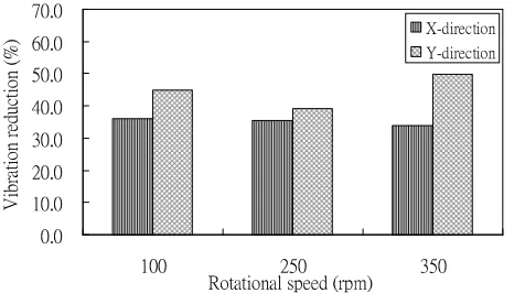
[image:5.595.53.286.591.724.2]Fig. 11 presents the summary of the tests under several rotational speeds in term of the percentage of vibration reduction of the system along two directions. The current set up is only a prototype, which is not rigid enough for higher speeds. Nevertheless, the outcome promoted the feasibility of using GMM actuators for actively controlled journal bearings. Also, the results do not show the optimal performance. There would have a large room for optimizing the system and its performance in the future study.
Fig. 11: Percentage reduction by the proposed idea under several rotational speeds
V. CONCLUSION
An idea of active control of journal bearing systems using GMM actuators has been proposed. The outcome shows that the shaft orbit is not exactly circular due to the non-linearity of the journal bearing dynamics. However, the size of the orbit can be significantly reduced by the GMM-based actuators in the control system. Thus, the experimental tests performed on this prototype system with actively controlled algorithm proved its feasibility. The next step should focus on the system performance test under transient mode of rotational speeds. At the same time, system performance optimization will also be one of the main goals in the future study.
ACKNOWLEDGMENT
We would like to extend our gratitude to Dr. Wu Chao of Zhengzhou Institute of Light Industry, China, for his constructive advice and comment on the work.
REFERENCES
[1] K. Y. Lum, V. T. Coppola, and D. S. Bernstein, “Adaptive
autocentering vontrol for an active magnetic bearing supporting a rotor with unknown mass imbalance”, IEEE Transactions on Control Systems Technology, vol. 4, no. 5, Sep. 1996, pp. 587-597
[2] M. N. Sahinkaya, A. H. G. Abulrub, P. S. Keogh, and C. R. Burrows, “Multiple sliding and rolling contact dynamics for a flexible rotor/ magnetic bearing system”, IEEE-ASME Transactions on Mechatronics, vol. 12, issue 2, Apr. 2007, pp. 179-189 [3] L. Sun, and J. M. Krodkiewski, “Experimental investigation of
dynamic properties of an active journal bearing”, Journal of Sound and Vibration, vol. 230, issue 5, Mar. 2000, pp.1103-1117 [4] Z. Cai, M. S. de Queiroz, and M. M. Khonsari, “On the active
stabilization of tilting-pad journal bearings”, Journal of Sound and Vibration, vol. 273, issue 1-2, May 2004, pp. 421-428
[5] A. Wu, Z. Cai, and M. S. de Queiroz, “Model-based control of active tilting-pad bearings”, IEEE-ASME Transactions on Mechatronics, vol. 12, issue 6, Dec. 2007, pp. 689-695
[6] A. B. Palazzolo, R. R. Lin, R. M. Alexander, A. F. Kascak, and J. Montague, “Piezoelectric pushers for active vibration control of rotating machinery”, Transactions of the ASME, Journal of Vibration Acoustics, Stress and Reliability in Design, vol. 111, issue 3, Jul. 1989, pp. 298-305
[7] H. G. Horst, and H. P. Wölfel, “Active vibration control of a high speed rotor using PZT patches on the shaft surface”, Journal of Intelligent Material Systems and Structures, vol. 15, issue 9-10, Sep.-Oct. 2004, pp. 721-728
[8] W. Li, P. Maißer, and H. Enge, “Self-learning control applied to vibration control of rotating spindles by piezopusher bearings”, Proc. Instn Mech. Engrs Part I: J. Systems and Control Engineering, vol. 218, 2004, pp.185-196
[9] R. C. Simões, and V. Steffen, “Modal active vibration control of a rotor using piezoelectric stack actuators”, Journal of Vibration and Control, vol. 13, issue 1, Jan. 2007, pp. 45–64
[10] C. Wu, W. Wang, B. F. Li, and P. L. Wong, “Smart journal bearing using giant magnetostrictive actuators, Part 1: Nonlinear stabiligy evaluation”, submitted to ASME Trans., J. of Tribo., 2009 0.0
10.0 20.0 30.0 40.0 50.0 60.0 70.0
100 250 350
Rotational speed (rpm) V
ib ra tio n re du ct io n (%
) X-direction
Y-direction
(a) (b)
[11] W. Wang, B. F. Li, C. Wu, K. D. Ma, and P. L. Wong, “Smart journal bearing using giant magnetostrictive actuators, Part 2: Experimental investigation”, submitted to ASME Trans., J. of Tribo., 2009 [12] T. L. Zhang, C. B. Jiang, H. Zhang, and H. B. Xu, “Giant
magnetostrictive actuators for active vibration control”, Smart Mater. Struct., vol. 13, issue 3, Jun. 2004, pp. 473-477
[13] H. M. Zhou, X. J. Zheng and Y. H. Zhou, “Active vibration control of nonlinear giant magnetostrictive actuators”, Smart Mater. Struct., vol. 15, issue 3, Jun. 2006, pp. 792-798
[14] S. J. Moon, C. W. Lim, B. H. Kim, and Y. Park, “Structural vibration control using linear magnetostrictive actuators”, Journal of Sound and Vibration, vol. 302, issue 4-5, May 2007, pp. 875-891
[15] S. John, J. Sirohi, G. Wang, and N. M. Wereley, “Comparison of piezoelectric, magnetostrictive, and electrostrictive hybrid hydraulic actuators”, Journal of Intelligent Material Systems and Structures, vol. 18, issue 10, Oct. 2007, pp. 1035-1048
[16] M. S. Kumar, “Development of active suspension system for automobiles using PID controller”, World Congress of Engineering 2008, vol. 1-3, 2008, pp. 1472-1477
[17] ETERMA Terfenol-D Data Sheet (ETERMA Products Inc., Ames, Iowa, USA)
[18] M. B. Moffett, A. E. Clark, M. Wunfogle, J. Linberg, J. P. Teter, and E. A. McLaughlin, “Characterization of Terfenol-D for magnetostrictive transducers”, Journal of Acoustical Society of America, vol. 89, issue 3, Mar. 1991, pp. 1448-1455