A Comparison of Induction Motor Speed
Estimation using Conventional MRAS and
AI-Based MRAS with a Dynamic Reference Model
Chao Yang and J. W. Finch
Abstract− The Model Reference Adaptive System (MRAS) is
probably the most widely applied speed sensorless drive control scheme. This paper compares induction motor speed estimation using conventional MRAS and AI-based MRAS with Stator Resistance Compensation. A conventional mathematical model based MRAS speed estimation scheme can give a relatively precise speed estimation result, but errors will occur during low frequency operation. Furthermore, it is also very sensitive to machine parameter variations. However, an AI-based MRAS-based system with a Stator Resistance Compensation model can improve the speed estimation accuracy and is relatively robust to parameter variations even at an extremely low frequency. Simulation results using a validated machine model are used to demonstrate the improved behaviour.
Index Terms− Dynamic Reference Model, Model Reference
Adaptive System (MRAS), Neural Networks, Induction Motor Control.
I. INTRODUCTION
Much effort has been devoted to speed-sensorless
induction machine drive schemes, with Model Reference
Adaptive System (MRAS) being the most popular [1]. In a
conventional mathematical-model-based MRAS, some state
variables are estimated in a reference model, (e.g. rotor flux
linkage components, ψrd, ψrq, or back e.m.f. components, ed, eq,etc.) of the induction machine obtained by using
measured quantities, (e.g. stator currents and perhaps
voltages).
________________________________________________
Chao Yang and Professor J.W. Finch are with the Electrical Drives Group, School of Electrical, Electronic & Computer Engineering, Newcastle University, NE1 7RU, UK. ([email protected], [email protected])
These reference model components are then compared
with state variables estimated using an adaptive model. The
difference between these state variables is then used in an
adaptation mechanism, which, for example, outputs the estimated value of the rotor speed (ωˆr) and adjusts the
adaptive model until satisfactory performance is obtained
[2-6].
Nevertheless, greater accuracy and robustness can be
achieved, if the mathematical model is not used at all and
instead, an AI-based non-linear adaptive model is employed.
It is then also possible to eliminate the need of the separate
PI controller, since this can be integrated into the tuning
mechanism of the AI-based model [7].
However, both the conventional MRAS and AI-based
MRAS scheme are easily affected by machine parameter
variations, which happen during practical operation [8,9]. In
this case, an online stator resistance estimator is applied to
the AI-based MRAS scheme which makes the whole scheme
more robust during computer simulation and could possible
make the scheme usable for practical operation [10, 11].
The comparison of schemes presented here is felt to be
valuable since much of the literature presents results for the
novel approach alone [1].
II. SPEED ESTIMATION USING CONVENTIONAL MODEL
REFERENCE ADAPTIVE SYSTEM
It is possible to estimate the rotor speed by using two
estimators (a reference-model-based estimator and an
adaptive-model-based one), which independently estimate
the rotor flux-linkage components in the stator reference
frame (ψrd, ψrq), and by using the difference between these
rq rd rd rq r
rψ ψ ψ ψ ψ
ψ
εω =Im( ′ˆ′*)= ˆ − ˆ
model to that of the actual speed [12]. The expressions for
the rotor flux linkages in the stationary reference frame can
be obtained by using the stator voltage equations of the
induction machine (in the stationary reference frame).
These give (1) and (2), which are now rearranged for the
rotor flux linkages:
] )
( )[ /
(
∫
− − ′= r m sD ssD ssD
rd L L u Ri dt Li
ψ (1)
] )
( )[ /
(
∫
− − ′= r m sQ ssQ ssQ
rq L L u Ri dt Li
ψ (2)
These two equations represent a so-called stator voltage
model, which does not contain the rotor speed and is
therefore a reference model. However, when the rotor
voltage equations of the induction machine are expressed in
the stationary reference frame, they contain the rotor fluxes
and the speed as well. These are the equations of the
adaptive model:
dt T i
L
Tr msD rd r r rq
rd (1/ ) ( ˆ ˆ ˆ )
ˆ ψ ω ψ
ψ = ∫ − − (3)
dt T i
L
Tr msQ rq r r rd
rq (1/ ) ( ˆ ˆ ˆ )
ˆ ψ ω ψ
ψ = ∫ − − (4)
The reference and adaptive models are used to estimate
the rotor flux linkages and the angular difference of the
outputs of the two estimators
is used as the speed
tuning signal. This tuning signal is the input to a linear
controller (PI controller) which outputs the estimated rotor
speed as shown in Fig. 1. The estimated speed can be
expressed as (5)
∫
+=Kp Ki dt
r εω εω
ωˆ (5)
Flux estimator, reference model
Flux estimator, adaptive model
Speed tuning signal
Kp+Ki/p
*) ˆ Im( ˆ
r r r
r ψ ψψ
ψ′× ′= ′ ′ r
ψ ′
r ψ ′ˆ
ω
ε
r ωˆ s u
s
i
Fig.1 MRAS-based rotor speed observer using rotor flux linkages for the speed tuning signal
III. ARTIFICIAL INTELLIGENCE-BASED
MODEL REFERENCE ADAPTIVE SYSTEM
The MRAS-based schemes described in the previous
section contain a reference model and an adaptive model.
However, greater accuracy and robustness can be achieved if
the mathematical model is partially replaced by a neural
network. It is then also possible to eliminate the need of the
separate PI controller, since this can be integrated into the
tuning mechanism of the neural network-based model.
The neural network-based model can take various forms:
it can be an artificial neural network (ANN) or a
fuzzy-neural network etc. and there is also the possibility of using
different types of speed tuning signals. It is believed that
some of these solutions can give high accuracy and are
relatively robust to parameter variations even at extremely
low stator frequency.
One specific implementation of the ANN-based MRAS
speed estimator system which is popular in academic work,
as shown in Fig. 2, which is similar to the conventional
MRAS system. In this new model, the adaptive model is
replaced by a simple two layer neural network, which
enables the whole system with fast response and better
accuracy than the conventional MRAS [13, 14].
Fig.2 MRAS-based rotor speed estimator containing a two-layer ANN
IV. MRAS BASED TWO-LAYER ANN SPEED ESTIMATOR WITH DYNAMIC REFERENCE MODEL
Compared to the conventional MRAS scheme, the MRAS
based rotor speed estimator containing a two-layer ANN
could give more accurate estimation result and relatively
replaces the adjustable model and adaptive mechanism in
the conventional MRAS, but the reference model is still
necessary for estimation the rotor flux which is used as
speed tuning signal. Several machine parameters are used to
build the conventional reference model, such as stator
resistance (Rs) and stator reluctance (Ls). These parameters
may change during the different periods of motor operating.
The values of these parameters are fixed in the reference
model. So the ANN speed estimator is still sensitive to
parameter variations especially during the motor low speed
running period.
To solve this problem and make this scheme more
independent to the machine parameters, a stator resistance
estimator is built in the new reference model, in which the
stator resistance Rs value could be estimated online. Fig. 3
shows the total scheme of neural network based MRAS with
a dynamic reference model.
In this new system, both the reference model and adaptive
model of the conventional MRAS system are modified for
better performance. The whole system can be divided into
two main parts, the dynamic reference model part and the
neural network part. The dynamic reference part consists of
the dynamic reference model derived from equations (1) and
(2), in which the stator resistance Rs is replaced by the
online estimated value Rˆ coming from equation (6) and (7), s
s i p s eR p K K
Rˆ =( + ) (6)
) ˆ ( ) ˆ
( rd rd sQ rq rq
sD
s i i
eR = ψ −ψ + ψ −ψ (7)
Dynamic Reference Model
Two-layer ANN Rs Tuning
Signal Adaptive Mechanism PI Controller Weight Adjustment Z-1 Z-1 Z-1 Z-1
W2Weight
usD usQ isD isQ rd ψ rq ψ + -+
-Fig.3 MRAS based ANN speed estimator with dynamic reference model.
The neural network part contains a simple two-layer
neural network, with only an input layer and an output layer.
Adjustable and constant weights are built in the neural
network, and the adjustable weights are proportional to the
rotor speed. The adjustable weights are changed by using
the error between the outputs of the reference model and the
adjustable model, since any mismatch between the actual
rotor speed and the estimated rotor speed results in an error
between the outputs of the reference and adaptive estimators.
To obtain the required weight adjustments in the ANN,
the sampled data forms of equations (3) and (4) are
considered. By using the backward difference method, the
sampled data forms of the equations for the rotor flux
linkages can be written as (8) and (9), where
T
is the sampling time. ) 1 ( ) / ( ) 1 ( ˆ / ) 1 ( ˆ / )] 1 ( ˆ ) ( ˆ [ − + − − − − = − − k i T L k T k T k k sD r m rq r r rd rd rd ψ ω ψ ψ ψ (8) ) 1 ( ) / ( ) 1 ( ˆ / ) 1 ( ˆ / )] 1 ( ˆ ) ( ˆ [ − + − − − − = − − k i T L k T k T k k sQ r m rd r r rq rq rq ψ ω ψ ψ ψ (9)Thus the rotor flux linkages at the kth sampling instant can
be obtained from the previous (k-1)th values as
) 1 ( ) / ( ) 1 ( ˆ ) / 1 )( 1 ( ˆ ) ( ˆ − + − − − − = k i T T L k T T T k k sD r m rq r r rd rd ψ ω ψ ψ (10) ) 1 ( ) / ( ) 1 ( ˆ ) / 1 )( 1 ( ˆ ) ( ˆ − + − − − − = k i T T L k T T T k k sQ r m rd r r rq rq ψ ω ψ ψ (11)
Introducingc=T/Tr, the following weights are given:
m r r r cL w T cT w c w = = = − = 3 2 1 1 ω
ω (12)
It can be seen that w1 and w3 are constant weights, but w2
is a variable weight and is proportional to the speed. Thus
equations (10) and (11) take the following forms:
) 1 ( ) 1 ( ˆ ) 1 ( ˆ ) (
ˆrd k =w1ψrd k− −w2ψrq k− +w3isD k−
) 1 ( ) 1 ( ˆ ) 1 ( ˆ ) (
ˆrq k =w1ψrq k− +w2ψrd k− +w3isQ k−
ψ (14)
These equations can be visualized by the very simple
[image:4.612.321.534.57.213.2]two-layer ANN shown in Fig. 4.
Fig. 4 Neural network representation for estimated rotor flux linkages
The neural network is training by the backpropagation
method; the estimated rotor speed can be obtained from:
) 1 ( ) / ( / )} 1 ( ˆ )] ( ˆ ) ( [
) 1 ( ˆ )] ( ˆ ) ( [ { ) 1 ( ˆ
) 1 ( ) / ( / ) ( ) 1 ( ˆ ) ( ˆ
2 2 2
− Δ + − −
+
− −
− + − =
− Δ + Δ
+ − =
k w T T k k k
k k k
k
k w T T k w k
k
rd rq rq
rq rd rd
r r r
α ψ
ψ ψ
ψ ψ ψ
η ω
α ω
ω
(15)
Where η is the learning rate and α is a positive constant
called the momentum constant. The inclusion of the
momentum term into the weight adjustment mechanism can
significantly increase the convergence, which is extremely
useful when the ANN shown in Fig. 4 is used to estimate in
real time the speed of the induction machine.
V. SIMULATION RESULTS AND DISCUSSION
To compare the conventional MRAS and the AI-based
MRAS with dynamic reference model, simulations are
established by using Matlab-Simulink software, based on
the standard well established validated 2-axis machine
model [6].
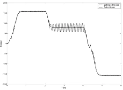
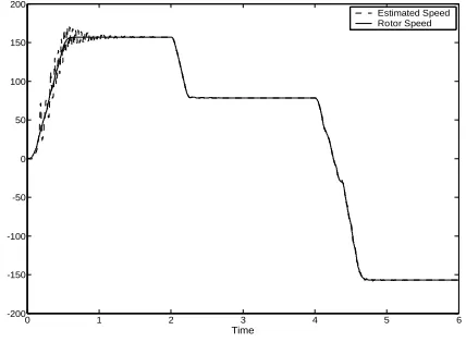
Speed estimation results using conventional MRAS and
neural network based MRAS are shown in Fig. 5 and Fig. 6
respectively. These results assume the machine parameters
are correctly measured and unchanged during operation.
Both of the two schemes can give good speed tracking
[image:4.612.73.291.107.256.2]results.
Fig. 5 Speed estimation using Conventional MRAS
Fig. 6 Speed Estimation using Two-layer ANN MRAS
Further simulation has been carried out with changed
stator resistance to test how much the parameter changing
would affect the speed estimation results.
[image:4.612.329.533.257.410.2] [image:4.612.320.535.514.672.2]Fig. 8 Speed Estimation using Two-layer ANN MRAS (with stator resistance Rschanged 2%)
In Fig. 7 and Fig. 8, simulations are carried out with the
stator resistance changed by a small amount, 2%. Obviously,
both schemes are still sensitive to parameter variations.
A final simulation for AI-based MRAS with the dynamic
reference model is shown in Fig. 9. The online estimated
stator resistance is displayed in Fig. 10. From the
simulation result in Fig. 9, the effect caused by the stator
resistance variation has been considerably improved.
0 1 2 3 4 5 6
-200 -150 -100 -50 0 50 100 150 200
Time Sp
e e d
[image:5.612.80.294.53.206.2]Estimated Speed Rotor Speed
Fig. 9 Speed Estimation using Two-layer MRAS with dynamic reference model
0 1 2 3 4 5 6
-0.5 0 0.5 1 1.5 2 2.5
Time R
s
Estimated Rs Rs
Fig. 10 Estimated Rsin the dynamic reference model
Comparing all the above simulation results shows that the
conventional MRAS scheme works well when the
parameters are precisely measured and do not change during
operation. The MRAS with adaptive model replaced by the
two-layer neural network can slightly improve the
performance when working in the same situation. But both
schemes can still be easily affected by parameters variations,
which do occur during practical operation. By introducing
the stator resistance online estimator, the performance is
much improved which should enable the scheme usable for
practical operation.
VI. CONCLUSION
The main objective of this paper is to compare
conventional MRAS and AI-based MRAS for induction
motor speed sensorless speed estimation. The conventional
MRAS can give good speed estimation in most of the
operation period, but errors will occur during low frequency
operation mainly caused by the machine parameter
variations. An AI-based MRAS system can give improved
accuracy and bypasses the PI controller tuning problems.
The simple structure of the two-layer neural network shown
in Fig. 4 yields a speed estimation system working online
with a fast response. Also the simple two-layer neural
network does not require a separate learning stage, since the
learning takes place during the on-line speed estimation
process. This is mainly due to the fact that the development
time of such an estimator is short and the estimator can be
made robust to parameter variations and noise. Furthermore,
[image:5.612.78.292.425.582.2]direct use of a speed-dependent mathematical model of the
machine.
However, the Two-layer neural network MRAS lies more
in the realm of adaptive control then neural networks. The
speed value is not obtained at the output, but as one of the
weights. Moreover, only one weight is adjusted in the
training. Therefore, it would still be sensitive to parameter
variations and system noise.
In the new approach, an online stator resistance estimator
is used to compensate the parameter variations. From the
comparison of the computer simulation results, it is obvious
that this new approach makes the whole scheme more robust
to parameter variations, which also gives the possibility of
practical use of the neural network based MRAS scheme.
The stator resistance estimator is working under adaptive
mechanism (PI controller). Further study could be carried
out for replace the PI controller with another simple neural
network which could also estimate more machine
parameters.
REFERENCES
[1] Finch, J. W. and Giaouris, D., Controlled AC Electrical Drives, IEEE Transactions on Industrial Electronics, Feb. 2008, 55, 1, pp. 1-11,. [2] Landau, Y.D., Adaptive Control the Model Reference Approach. 1979:
Marcel Dekker.
[3] Vas, P., Sensorless Vector and Direct Torque Control, 1998: Oxford University Press.
[4] Shauder, C., Adaptive Speed Identification for Vector Control of Induction Motors without Rotational Transducers. IEEE Transactions on Industry Applications, 1992, 28.
[5] Yang, G. and T. Chin, Adaptive-Speed Identification Scheme for a Vector-Controlled Speed Sensorless Inverter-Induction Motors. IEEE Transactions on Industry Applications, 1993, 29.
[6] Fitzgerald, A.E., C. Kingsley, and S.D. Umans, Electric Machinery.
6th ed., 2003: McGraw-Hill International Edition.
[7] Vas, P., Artificial-Intelligence-Based Electrical Machines and Drives. 1999: Oxford University Press.
[8] Kumara, I.N.S., Speed Sensorless Field Oriented Control for
Induction Motor Drive. PhD Thesis, 2006, University of Newcastle upon Tyne.
[9] Leonhard, W., Controlled AC drives, a successful transition from
ideas to industrial practice. Elsevier Science, 1996.
[10] Zhen, L. and L. Xu, Sensorless Field Orientation Control of Induction
Machines Based on a Mutual MRAS Scheme. IEEE Transactions on
[11] Holtz, J. and J. Quan, Drift-and Parameter-Compensated Flux Estimator for Persistent Zero-Stator-Frequency Operation of
Sensorless-Controlled Induction Motors. IEEE Transactions on Industry Applications, 2003, 39.
[12] Ohtani, T., N. Takada, and K. Tanaka, Vector Control of Induction Motor without Shaft Encoder. IEEE Transactions on Industry Applications, 1992, 28.
[13] Peng, F.Z. and T. Fukao, Robust Speed Identification for
Speed-Sensorless Vector Control of Induction Motors. IEEE Transactions on Industry Applications, 1994, 30.
[14] Vasic, V. and S. Vukosavic, Robust MRAS-based Algorithm for Stator