Abstract: An experimental micromagnetoflowcell viscometer was fabricated to enable viscosity measurements for microscopic quantities of liquid. The device uses measurement of the terminal velocity of superparamagnetic microparticles to determine the fluid properties. Motion of these particles is controlled by the magnetic field generated from microscopic electromagnetic loops. Analytical modelling has been carried out to predict the pattern of the magnetic field. Magnetic forces in the range of 10-9 to 10-12 N are generated at a current density of 109A/m2. An experimental micromagnetoflowcell has been designed and fabricated and initial experiments have been conducted, using high speed video microscopy. These demonstrate local control of the particles using the magnetic fields, but there is a tendency for the particles to agglomerate in water based fluids, requiring surfactant treatment in future experiments.
Keywords: Superparamagnetic microparticles, viscometer
I. INTRODUCTION
The advantages of microfluidic systems for analytical applications are [1]:
1. The possibility of using minute quantities of fluids (down to picoliters)
2. Short reaction times when molecular diffusion lengths are of the order of the microchannel dimension
3. A large surface to volume ratio, for surface based assays. Superparamagnetic microparticles have been used extensively in magnetic separation, immuno-assays, magnetic resonance imaging, drug delivery and hyperthermic tumour therapy [2]. Such small particles can be used in bio-assays, or even in vivo
applications. The microparticles used in this work (M450 Dynabeads ®) are spheres of approximately 5 μm diameter with embedded superparamagnetic regions and can, therefore, be manipulated using permanent magnets or electromagnets independently of microfluidic or biological processes. Each microparticle consists of individual monodomain superparamagnetic nanoparticles (γ –Fe2O3) encapsulated by a polystyrene surface which is highly hydrophobic. It is
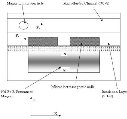
[image:1.612.316.539.347.556.2]magnetized in the presence of a magnetic field and demagnetized once the magnetic field is removed [3]. By combining magnetically driven superparamagnetic microbeads with microchannel fluidics, it is in principle possible to drive the beads through the microchannel and, by monitoring their transport properties, to measure the viscosity of the microscopic quantity of fluid in the channel. This is the principle of the micromagnetoflowcell, which is similar in some respects to systems used to study the elasticity of gelatine gels [4].
Figure 1: Schematic cross section through the micromagnetoflowcell showing one of the linear array of microcoils. The NdFeB permanent magnet is used to saturate the superparamagnetic particles which are transported along the channel by the action of the magnetic coils.
II. THEORYANDPRINCIPLEOFOPERATION In operation, the magnetic particles are saturation magnetized using a uniform magnetic field from a NdFeB permanent magnet of strength ~50mT. Transport of the particles is effected through a non-uniform magnetic field generated from the array of microcoil electromagnets. Motion of the particles is recorded and measured using video microscopy.
The Micromagnetoflowcell - A Microfluidic
Viscometer
C S Lo1, P. D. Prewett1, G J Davies1, C J Anthony1 and K Vanner 2
1 MicroEngineering and Nanotechnology Group, School of Engineering, University of Birmingham,
Transport of the particles is driven by the non-uniform magnetic field along the microchannel, due to the microcoils. Resistance to this transport is due to viscous drag and the balance between drive and drag enables the viscosity to be determined.
The magnetic moment of a particle can be derived from the derivative of the magnetic energy, U. In the case of the superparamagnetic particle, the magnetic moment in a non-magnetic medium is defined as [5]
H
H
M
i i mN
χ
χ
χ
+
=
=
1
(1)where V (m3) is the volume of the particle, µ
0 =4π × 10-7 N/A2 is the vacuum magnetic permeability, χm is the measured magnetic susceptibility and H (A/m) is the external applied magnetic field in the absence of the magnetizable object. N represents the demagnetizing factor for a spherical particle with a value of N=1/3. The particle becomes magnetized when it acquires sufficient magnetic potential energy to overcome its thermal energy barrier [6].
Um =
-
m.B
≥ kBT (2) where kB is the Boltzmann’s constant, T (0K) is the ambient temperature and B(T) is the external magnetic field. Magnetic induction generated from the microcoil is in the range of 1-10mT; the maximum current which can be used to drive the coil is limited by the effects of Joule heating and electromigration [7]. An additional difficulty is that the magnetic susceptibility χm of the beads is rather weak, due to the effects of demagnetization and the small magnetic core volumes.The magnetic induction, B of a coil can be determined from the magnetic vector potential A, where
B =
∇
× A (3)The magnetic vector potential, A of a microcoil is [8]
φ
π
θ
μ
a
A
0 24
sin
r
m
=
(4)where m (A/m2) is the magnetic dipole moment, πr
t2I , rt is the radius of the ring, r is the position vector and aø is the unit
vector. The external field imposes a permanent magnetic moment on the particles and the coils generate the magnetic field gradient which manipulates the movement of the particles. The key parameter is therefore
∇
B, due to the coils, which produces a magnetic force, Fm on the particle.(
B.)
BF = ∇
0
μ χm m
V
(5)
If the flow has low Reynold’s number, the inertial effect can be ignored. As the particles are transported along the x-direction, the motion is resisted by the hydrodynamic drag force which is determined through Stokes’ equation:
v
6
F
drag=
−
π
r
bη
(6)where η (Pa.s) is the viscosity of the fluid, rb (m) is the radius of the particle and v (m/s) is the velocity of the particle in the fluid. When the magnetodrive and fluid drag forces are equal, equations (5) and (6) predict the maximum particle velocity that can be generated by magnetic force in an initially stationary fluid:
( )
η μ χ 0 2 9 B B. 2v= R ∇ (7)
The particle attains its terminal velocity when all the forces cancel out after a time of the order of 1μs [9].
η
ρ
τ
9
2
2 bead br
=
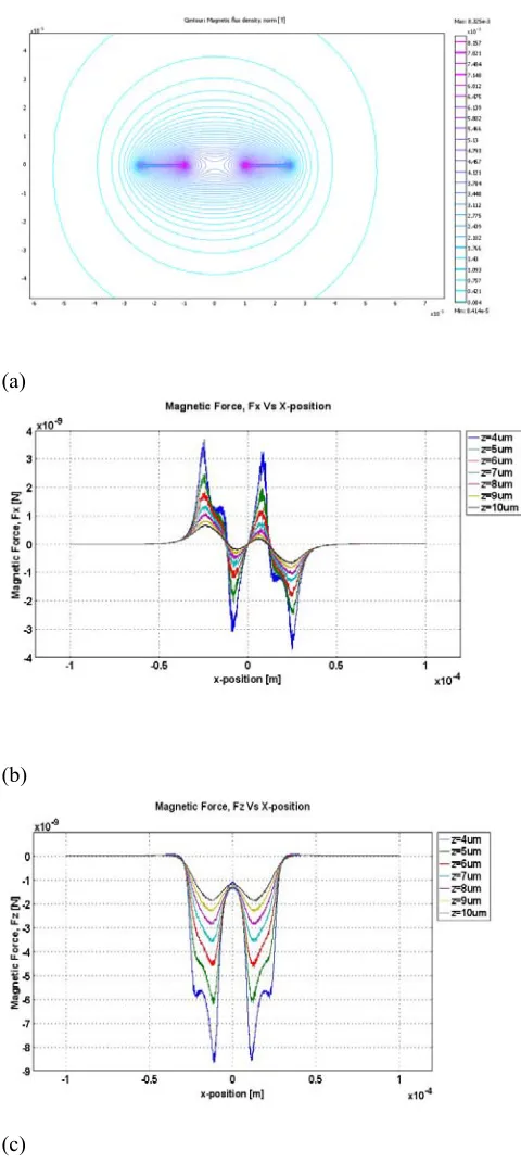
≈ 10-6 s (8)where ρbead (kg/m3) is the density of the magnetic particle. The results of this analytical model are shown in Figure 2. The magnitude of the average magnetic forces range from 10-9 N to 10-11 N. Based on these average forces, the viscosities of various fluids may be determined by measuring the time of flight of the particle trajectory in different media.
m b
F
r
D6
π
η
=
flight
t
(9)where D is the distance traveled between coils.
The force generated by the magnetic coils may be resolved into that in the plane of the channel and that perpendicular to it. The former will generate the required transport along the channel axis, but the latter produce the unwanted effect of trapping the particles at the interface between the channel and the microcoils.
magnetic particles would concentrate at the corners of the coil where the magnitude of the magnetic force is highest.
(a)
(b)
[image:3.612.46.286.91.627.2](c)
Figure 2: (a) Contour plot of the normalized magnetic flux density at J =109 A/m2 (b) Magnetic drive force X (translational force) and (c) Z (trapping force) values at varying z-height measured along the x-axis.
III. DESIGNANDFABRICATION
The layout of the micromagnetoflowcell is shown in Figure 3. Several identical microchannels are located between input and output reservoirs and the single loop microcoils are accessed via current drive lines, connected to bond pad arrays. The optical micrograph shows an array of microcoils of outside diameter 50 µm, with track width 50 μm and thickness 1 μm; the microchannel width is nominally 400 µm with a depth of 50µm and length 20mm. The coils are separated by 65µm. An insulation layer on top of the micro-coils prevents electrical shorting by the fluid under test. The microchannels are sealed with a layer of poly-dimethylsiloxane (PDMS).
Figure3: (a) Top: CAD schematic of the magnetoflowcell viscometer. (b) Middle: Micrograph of the microcoils embedded underneath a layer of SU-8 resist. (c) Bottom: SEM image of the microfluidic channel with several parallel filters.
resist , spun to a thickness of 2µm and soft-baked. Once the pattern is transferred, by photolithography, the substrate is hard baked and developed. The first layer is cured and a second layer of SU-8 50 is spun over the insulation surface to form the microfluidic channel. Similar processing steps are used to form a 50µm layer of SU-8. The device is bonded onto a PCB board with wire bonded feedthroughs to the chip contact pads. Finally, the microchannel is sealed using a PDMS lid. The key steps in the fabrication process are outlined schematically in Figure 4.
(a)
(b)
(c)
(d)
(e)
S1813 Pyrex 7740
Au/Cr SU-8 50
SU-8 2002 PDMS
Figure 4: Microfabrication steps for the micromagnetoflowcell (a) A layer of S1813 is deposited over the surface of the gold to provide a mask layer before the proceeding to the wet-etching process. (b) Unwanted gold is removed, leavigt the coil pattern. (c) A layer of SU-8 2002 is deposited over the surface of the coils. (d) The microfluidic channel is fabricated in a layer of SU-8 50 deposited on the surface of the microcoil insulation layer. (e) The microfluidic channel is sealed with a layer of PDMS.
IV. EXPERIMENTS
The magnetic properties of the paramagnetic microparticles were determined using a vibrating sample magnetometer (VSM). The saturation magnetization is in the range 400-600 A/m, as seen from Fig 5, which shows the antihysteresis curve typical of paramagnetic materials.
Volume Magnetization Vs Magnetic Flux Density
-800 -600 -400 -200 0 200 400 600 800
-2.5 -2 -1.5 -1 -0.5 0 0.5 1 1.5 2 2.5
Applied Magnetic Flux (T)
Vol
u
m
e M
agne
tizatio
n
(A
/m
)
[image:4.612.42.297.173.517.2]M-450
Figure 5: VSM measurement of microbeads showing antihysteresis due to superparamagnetism.
The final experimental micromagnetoflowcell chip, as shown in the photograph in Figure 6, was mounted on an optical microscope stage and the coils were activated using a PICAXE microcontroller, providing a drive current of 0.1 A. Movement of the particles along the microchannels was viewed by microscope through the capping layer of PDMS, which is transparent to visible light. Video images of the particle trajectories were captured using a high speed CCD camera at 250 fps. Prior to the experiment, the microbeads were dispersed in de-ionized water containing 1% by weight Triton X-100 (~ 4 × 10⁸ beads/ml). Triton X-100 is a non-ionic surfactant which prevents the particles from aggregating and helps to stabilize the beads in suspension. [11]
Small bubbles started forming when the coils were activated, thus creating an air gap in the microchannel. This is a result of poor sealing between the SU-8 microfluidic channel and the PDMS lid. Due to low magnification, the image resolution of the particles was quite poor causing difficulties in studying bead trajectories when the dimensions of the microfluidic channel are large compared to the bead diameter and in the absence of agglomeration. However, the images were adequate to show that most of the particles were close packed on the edges of the coil, as is evident from Figure 7.
SU-8 is highly hydrophobic due to its chemical structure which consist of an aromatic ring and epoxy functional part resulting in a large water contact angle after cross-link [12]. Consequentially, there was a certain degree of difficulty in transmitting fluid through the narrow microchannel. Furthermore, due to the hydrophobic surface of the particles, there was a tendency for these particles remain attracted to the SU-8 microfluidic channel wall which could ultimately result in blockage in the microchannels.
Figure 6: Photomicrograph showing the experimental arrangement. Microchannels are sealed using PDMS. Fluid is transferred through an inlet tube connected to the chip through the PDMS capping layer.
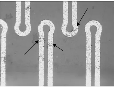
There is a tendency for the particles to stick upon arrival at the coil edges. This is not an edge effect as the coils are separated from the channels by a layer of SU-8. We believe it to be due to the hydrophobic nature of the particles surfaces which leads to agglomeration of particles, as seen from the magnified image in Figure 8.
Field gradient induced local motion has clearly been observed, but there is still work to be done if this is to be extended to longer range motion along the complete length of the microchannel. This will require a “phased” electrical drive current distributed among the coils to drive particles in a quasi-continuous fashion. In addition, the tendency for the particles to agglomerate must be overcome, through modification of the surface chemistry of the styrene coating of the paramagnetic microparticles and/or improved surfactant, if the system is to work as planned in water based fluids.
V. CONCLUSIONS
The concept of the micromagnetoflowcell, for use inter alia as
a microviscometer, has been explained and its design and theoretical analysis presented. The microparticles should reach their terminal velocity within a microsecond and measurement of their transport between coils should enable measurement of viscosity from microscopic quantities of fluids.
An experimental micromagnetoflowcell has been fabricated and experiments have begun. Initial results show that the microparticles can be controlled locally through the action of the microcoil array, but more work is required to produce constant velocity flow along the length of the channel. This will require further development of the electrical control circuit and the addition of a surfactant to overcome the tendency of the microparticles to agglomerate in water based fluids. Techniques such as wet-chemical or plasma based process could be used to modify the surface of the SU-8. Both processes would render the surface hydrophilic by reacting
[image:5.612.314.506.121.505.2]with the SU-8 epoxy group [13, 14]. As a result, the surface would display a low contact angle which should allow liquid to be transmitted more easily into the microfluidic channel through capillary pressure. [15,16]
[image:5.612.313.512.561.710.2]Figure 8: Optical micrograph at 50X magnification, showing agglomeration of microparticles arriving at the activated coil regions.
REFERENCES
[1] Darwin R. Reyes, Dimitri Iossifidis, Pierre-Alain Auroux and Andreas Manz: Micro Total Analysis Systems. 1. Introduction, Theory and Technology, Anal. Chem. 74, (2002) 2623-2636.
[2] Martin A. M. Gijs, Magnetic bead handling on-chip: new opportunities for analytical applications, J.
Microfluidics and Nanofluidics, 2004, 1 pp. 22-40. [3] Sinclair, B. To Bead or Not to Bead: Applications of
Magnetic Bead Technology The Scientist , 1998
12(13):17
[4] H. Freundlich & W. Seifriz, Zeitschriff fur Physikalische Chemie 104 (1922) 233
[5] Christian Mikkelsen, Mikkel Fougt Hansen and Henrik Bruus, Theoretical comparison of magnetic and hydrodynamic interaction between magnetically tagged particles in microfluidic systems J. Magn.
Magn. Mater. (2005) 293 pp 578-83
[6] Robert C. O’ Handley, Modern Magnetic Materials: Principles and Applications, Wiley, New York, 1942.
[7] S.M. Sze, VLSI Technology Mc Graw Hill, New
Jersey, 1983.
[8] B.I. Bleaney and B Bleaney, Electricity and Magnetism, Clarendon, Oxford, 1965.
[9] Kristian Smistrup, Ole Hansen, Henrik Bruus, Mikkel F. Hansen, Magnetic separation in microfluidic systems using microfabricated electromagnets – experiments and simulations. J. Magn. Magn. Mater.
(2005) 293 pp 597-604.
[10] H. Lee, A.M. Purdon, and R.M. Westervelt,
Manipulation of biological cells using a microelectromagnet matrix. App. Phys. Lett. 79
(2004) , pp 3308-3310
[11] R, Bubeck, S. Neser, C. Bechinger, and P. Leiderer, Prog. Colloid Polym. Sci. 110, 41 (1998)
[12] C.L Wung, M.H. Chen, F.G.Tseng, SU-8 Hydrophilic Modification by Forming Copolymer with Hydrophilic Epoxy Molecule, 7th Inter. Conf. M.C. &
B. Anal. Syst. (2003) pp 117-1120
[13] M. Nordstorm, R. Marie, M. Calleja and A. Boisen,
Rendering SU-8 hydrophilic to facilitate use in micro-channel fabrication, J. Micromech. Microeng.,
14, (2004) pp. 1614-1617.
[14] F. Walther, P. Davidovskaya, S. Zurcher, M. Kaiser, H. Herberg, A. Gigler, R. W. Stark, Stability of the hydrophilic behaviour of oxygen plasma activated SU-8 J. Micromech. Microeng.
[15] Dong M and Chatzis I 1995 J. Colloid Interface Sci. 172 278-88.