Digital Transceiver using H-Ternary Line Coding Technique
A. MahadevanAbstract – In this paper “Digital Transceiver using Hybrid Ternary Technique” gives the details about digital transmitter and receiver with the design of a hybrid ternary line coding. Current applications of line codes are enormous in data transmission networks and in recording and storage of information systems. The applications include local and wide area networks both wireless and wire connected and the technology of the digital subscriber loops networks. A coding technique named hybrid ternary line code can be derived from three popular line codes NRZ-L, dicode NRZ and polar RZ.
Keywords: - Binary Line Code, Ternary
Line Code, FSK Modulation, FSK Demodulation, VCO, PLL and Power Spectral Density (PSD)
1 Introduction
Line coding is the process of converting a sequence of 1s and 0s to a time domain signal (a sequence of pulses) suitable for transmission over a channel.
Manuscript submitted on December 30, 2006; accepted January 30, 2007.
A.Mahadevan, PG Student, Department of ECE, Adhiyamaan Engineering College, AERI, Hosur, Tamil Nadu, India 635 109 (e-mail: [email protected])
using simple combinational logic circuits. The digital modulation technique called Frequency Shift Keying (FSK) is used in the modulator and demodulator. Then, the Power Spectral Density (PSD) of the H-Ternary code is analyzed by comparing with other line codes like as unipolar NRZ, Bipolar NRZ and Manchester coding etc. with the help of MATLAB programming.
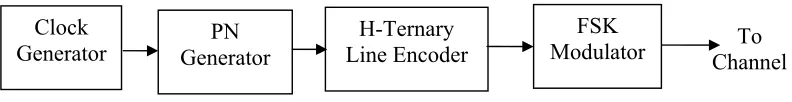
2 Design of Digital Transmitter
The transmitter has consisted of three major blocks. One is the binary random data signal generator. This can be constructed by Pseudo-Noise (PN) or Pseudo-Random sequence generator. Second is the H-Ternary line encoder stage. This stage is mainly concentrated in this project. And finally it has a digital
modulator (FSK) stage which is used to transmit the encoded PN sequences through the channel. In this project, the channel is considered as a wired channel. A block diagram of the transmitter is as shown in the Fig. 2.
3 Principles and Design of
H-Ternary Line Encoder
This code worked on the basis of hybrid principle that combines three binary codes. The polar NRZ (NRZ-L), dicode NRZ and Polar RZ codes are involved in the Hybrid Ternary line coding [1]. Three levels are used to represent the H-Ternary output. These are positive (+), negative (-) and zero (0). The state of the line code is in any one of the three levels. The state of the next level of the line code is depends on the input binary 1 or 0 and present
Clock
Generator Generator PN Line Encoder H-Ternary
FSK Modulator
Fig. 2 Block diagram of Transmitter
To Channel Error Coding
for security / Multiplexing
Line Coder
Low-Pass Channel
Band-Pass Channel Modulator
or Input
signal
Fig.1 Place of line coding in the communication system
[image:2.612.106.523.66.160.2] [image:2.612.128.524.615.666.2]Leveling
Circuit VCO H-ternary
Encoded data
FSK output
Fig. 3 Block diagram of FSK modulator state of the line code. There is no
mathematical relation between this H-ternary line code and the basic three codes NRZ-L, dicode NRZ and polar RZ codes. When the PN sequence is occurs like as 10101010…, the H-ternary code will acts as NRZ-L code. If the sequence of PN signal is occurs like as 1111111… or 000000…, the H-ternary code will be act as polar RZ and dicode NRZ. The function of the encoder is as shown in state table 1.
Table 1 State table for encoder Input Binary Output H-Ternary
Present State Next State
1 0 + 1 - + 1 + 0 0 - 0 0 + - 0 0 -
In order to get the design of the encoder, the above table is modified as a truth table by assigning values to +, 0 and – signs. The values for +, 0 and – are assigned as 10, 00 and 01 respectively. The encoder circuit is designed from the Boolean expression which is obtained from the truth table. The encoder circuit is designed by simple combinational circuit and analog subtractor.
4
Design of FSK Modulator
The simplest method to generate the FSK signal is Voltage Controlled Oscillator (VCO). The VCO is a free running multivibrator and operates at a setfrequency f0 called free running frequency. This frequency is determined by an external timing capacitor and an external resistor. It can also be shifted to either side by applying a dc control voltage vc to an appropriate terminal of the VCO IC. The frequency deviation is directly proportional to the dc control voltage and hence it is called a Voltage Controlled Oscillator or, in short, VCO. The block diagram of FSK modulator using VCO is as shown in Fig. 3.
5 Design of Digital Receiver
The receiver has consists of three major blocks. One is the FSK demodulator for detecting the signal from the FSK output. Second stage is H-ternary line decoder. And finally it has a clock recovery signal for proper decoding process. The clock recovery circuit is essential for making synchronisation between transmitter and receiver. A block diagram of the receiver is as shown in the Fig. 4.FSK Demodulator
H-Ternary Line Decoder
Clock Recovery Circuit
Fig. 4 Block diagram of receiver
From channel
[image:3.612.101.304.314.433.2]6
Design of FSK Demodulator
The block diagram of FSK demodulator using Phase Locked Loop (PLL) is as shown in Fig.5. FSK demodulation ordetection can be directly achieved by using PLL circuit. If the PLL center frequency is designed at the FSK carrier frequency, the filtered output voltage of the circuit is the desired demodulated signal, varying in value proportional to the variation of the signal frequency.
[image:4.612.325.533.60.249.2]7 Principles and Design of
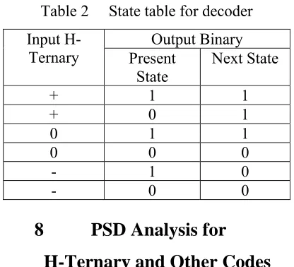
H-Ternary Line Decoder
The design of the H-ternary decoder is based on the state table 2. The decoding is a reverse process of the encoding operation. The decoder input is in the form of three bit H-ternary code and its output is a two state binary signal. In order to design the decoder circuit , the state table is modified to truth table by assigning the values for +, 0, and – signs. The decoder circuit consists of a clock recovery circuit. This is used to synchronize the transmitter circuit with receiver circuit.Table 2 State table for decoder Input
H-Ternary Present Output Binary State
Next State
+ 1 1 + 0 1 0 1 1 0 0 0 - 1 0 - 0 0
8
PSD Analysis for
H-Ternary and Other Codes
Since, considering the input data sequence is random, stochastic analysis technique is adopted to find the PSD. The PSD general expression of a digital signal is given by, [image:4.612.103.291.158.230.2]where, S(f) is the Fourier transform of the pulseshape and R(k) is the autocorrelation function of the data. The spectrum of the digital signal depends on two things: (1) the pulse shaped used and (2) statistical properties of the data. And the above equation (1) can be rewritten in a simpler series form as follows
Fig. 5 Block diagram of FSK demodulator
FSK signal
Demodulated signal
PLL LPF Comparator
| S(f) |2
Pc(f) = --- Σ R(k)e j 2π f k Tb (1) Tb
+∝
k = -∝
| S(f) |2
Pc(f) = ---[R(0)+2ΣR(k) cos (2πkfTb)]
Tb (2)
+∝
k = 1
For the basic pulse s (t), has a rectangular pulse of unit amplitude and duration Tb. Hence, the Fourier transform of s(t) equals
S(f) = Tb sinc (fTb) (3)
The statistical properties of the data is referenced to the autocorrelation function of the line code that is given by
R(k) = Σ ( A m A m + k ) i Pi (4)
l
i = 1
where, Am and Am+k are the signal levels that correspond to the mth and m+kth symbol positions that represent the line code respectively and Pi is the probability of having the ith A
m and Am+k product. To
calculate the autocorrelation function of symbols, it needed to calculate the value of R(0). The probability of occurrences of each symbol of the H – Ternary line code is equal. This gives the probability of the three transmitted code levels are equal. Therefore the probabilities are given as P+ = P0 = P- = 1/3. The autocorrelation R(k) can be calculated by using the eqn. (4).
If k = 0, R(k) is calculated for N signal symbols and averaging the same signal symbols. If k ≠ 0, R(k) can be determined
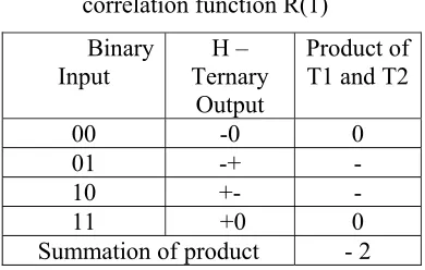
[image:5.612.337.532.202.326.2]by using the following method. The following table 3 shows the binary input and it’s H – Ternary outputs with the product of the designated signal levels. The probability of each case is also
Table 3 Determination of the auto- correlation function R(1)
Binary Input
H – Ternary
Output
Product of T1 and T2
00 -0 0 01 -+ - 10 +- -
11 +0 0
Summation of product - 2
depending on the number of H – Ternary symbols that are considered. For example, from the above tables, the probabilities of each symbols are P1=¼, P2=1/8, P3=1/16 and so on. By using the eqn (5), the autocorrelation function for each case is calculated as R(1)=(-2) ( ¼) = - ½ , R(2) = (+2)(1/8)=¼ and R(3) = (-2) (1/16) = -1/8. The overall autocorrelation functions for all values of k excluding k = 0, is given as R(k) = 2 [-1k / 2k+1] = (-1/2) k (6)
Substituting the eqn. (5) and eqn. (6) together with eqn. (3) into eqn. (2) gives the PSD of the H – Ternary line code that is,
(Tb) sinc2 (fTb)[R(0)+2ΣR(k)cos(2πkfTb)] (7)
+∝
k = 1 R(k) = Σ ( A m A m + k ) i Pi
R(0) = 1/N [N/3 (+1)2 + N/3 (-1)2 + N/3
The PSD of the H–Ternary line code is a re-shaped form of the Fourier transform of a rectangular pulse having ±A amplitude and duration of Tb. So, the above equation can be rewritten as
A2(Tb)sinc2(fTb)[R(0)+2ΣR(k)cos(2πkfTb)]
(8)
The above eqn. (8) is known as the power spectral density (PSD) of the H-Ternary line code. Similarly, the PSD for the other codes are calculated and given as follows,
Polar NRZ = A2 T
b sinc2 (fTb)
Bipolar NRZ = A2T
bsinc2(fTb) sin2(πfTb)
Unipolar NRZ = [(A2Tb)/4][sinc2(fTb)] [1+ (1/Tb) δ(f) ]
BipolarRZ =A2Tb/4sinc2(fTb/2)sin2 (πfTb)
9
Simulation Results And
PSD Analysis
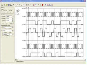
The simulated graph is as shown in figure 6. The PN signal and H-ternary encoded signals of the implemented system are shown in figure 7. The transmitted and received PN signals are as shown in figure 8. The results are giving 2 bit time delay
due to involving memory elements in the circuits. PSD analysis of the H-ternary line coding is done by MATLAB 7.0
References
[1] Glass, A., Ali, B. and Bastaki, E. “Design and modeling of H-Ternary line encoder for digital data transmission”. International Conference on Info-Tech & Info-Net, Beijing, China, 2001, pp 503-507.
Fig. 8. Transmitted and Received PN signals
[image:6.612.340.524.122.609.2]Fig. 7 PN signal and H-Ternary encoded signal
[image:6.612.108.292.594.732.2]Figure 9 PSD for various line codes
Fig. 6 Simulation results of encoder and decoder