James C. Hirschi
William M. Leue
2Walter H. Berninger
2Richard H. Hamilton
3Gerald F. Abbott
1Received May 5, 1980; accepted after revision July 17,1980.
I Department of Radiology, New York Hospital-Cornell Medical Center, New York, NY 10021. Address reprint requests to J. C. Hirschy, 61 E. 66th St., New York, NY 10021.
2 General Electric Corporate Research and De-velopment Center, Schenectady, NY 12301.
3 Department of Radiology, New York Univer-sity School of Medicine, New York, NY 10021.
This article appears in November/December 1980 AJNR and January 1981 AJR.
AJNR 1 :551-556, November/December 1980 0195-6108/80/0016-0551 $00.00
© American Roentgen Ray Society
551
CT of the Lumbosacral
Spine:
Importance of Tomographic
Planes Parallel to Vertebral End Plate
An experimental computer program capable of reformatting stored display data from a CT scanner into true cross-sectional images of the spine has been clinically tested over a 1 year period. With this program, tomographic planes exactly parallel to the vertebral end plate can be imaged at the lumbosacral level even in patients who are markedly rotated or have scoliotic deformities. The reformatted image planes are tilted in the dorsoventral and mediolateral directions to compensate for lordosis or scoliosis. The reformatting can also produce images in coronal and sagittal planes on axes other than true horizontal or vertical. The program has been used in the examination of 269 spines and has been found to be valuable in demonstrating the spinal canal and the intervertebral foramina.
The computed axial tomogram should be the ideal instrument for the exami-nation of the spine, particularly for the evaluation of the size and shape of the spinal canal and the intervertebral disc. However, several technical limitations have hindered its completely successful application and, in a recent report by Mankin and Teng [1], preoperative evaluation of the spinal canal by CT was described as unreliable compared with the myelogram.
One of the problems with CT examination of the spine has been the inability to determine the exact position of an axial image within the spine. The placement of radiopaque catheters of graduated length on the patient's skin and correlating the number of catheters seen in the cross section on the CT image with the number of catheters at a specific level seen on the preliminary radiograph provided a useful but somewhat awkward solution to the problem of localization
[2-4 ].
A better solution is the digital projection radiograph (GE-Scout View) that can be viewed on the CT monitor. An electronically generated line can be precisely located on the digital radiograph and the CT scanner can be programmed to obtain an axial image at that level [5].
Excessive thickness of the tomographic section has also been a problem, since small abnormalities become lost in the summation of data from a thick slice [6-8]. The recent availability of 1.5-2.0 mm scan collimation has surmounted this obstacle.
A further problem has been the inability to align the plane of the cross section at right angles to the long axis of the spinal canal or parallel to the vertebral end plate [9]. This problem is overcome in the upper four-fifths of the lumbar spine by tilting the gantry. The digital radiograph can then be used to determine the desired angle of gantry tilt for each axial slice. Unfortunately, the tilt has been insufficient to enable the plane to become parallel to the lumbosacral disc (L5-S1) in more than 96% of the patients in this series. Many patients also have lateral curvatures (scoliosis) and there is no mechanical means of making the scan plane parallel to the laterally tilted vertebrae.
552 HIRSCHY ET AL. AJNR:1, November/December 1980
•
Fig. 1.-Axial CT slices of lumbosacral spine can give images of normal lumbosacral spine that have different appearances depending on where slice is made in relation to spinal curve. Crosshatch lines represent various slices and boxes represent axial images. Slice A represents a normal disc. Slice B mimics herniated disc. Slice C shows disc material between two bones.
Fig. 2.-0n lateral digilal radiograph of lumbar spine, electronic line (a) is true vertical. Line b is -150 from vertical and represents mechanical limit of ganlry tilt. Line c passes through interverlebral disc space at 54.30 from vertical.
stored display data from adjacent, nonoverlapping tomo-graphic sections to be reformatted into planes different from those originally set with the gantry. The application of similar techniques was reported by Lancourt et al. [10] and Glenn et al. [11]. With this program, the image plane can be tilted in the coronal and sagittal planes, and the entire plane can be rotated. A tomographic plane exactly parallel to the vertebral end plate can be selected to show an undistorted cross section of the spinal canal or the intervertebral disc.
An axial slice that is not at right angles to the neural canal can give the false impression of a disc extruding into the neural canal. This is particularly true at L4-L5 and L5-S1, when the projected image includes the posterior margin of the intervertebral disc (fig. 1). However, what appears to be a soft-tissue density disappears when the image is refor-matted to be perpendicular to the spinal canal and parallel to the intervertebral disc space.
Fig. 3.-Line C on lateral digital radiograph passes through the L5-S1 intervertebral disc space. In order to examine disc space, contiguous 5 -mm-thick nonoverlap ping axial slices are taken. Information is rearranged to synthesize new image representing line C.
.
,
1.5mmN
'f----: 1---f---- l
-'I - -
Ir
,C
ll:=:
I
t::
~,I'MULTIPLE SCANS
(.Smm -GAPPING" I
-G.E.BBOD
120~V. 760mAS 19.6 Secolld5 J
-10.~
-
-
-S.Omm
-~
Il
l
l
I
-Ir==
I
t::
~
I
I=::
! ' ~/'~
MULTIPLE SCAN~
ICONTIGUOUS)
: 1
-
II
I
-
I---Ir
c
I
~
SINGLE ~CAH ,,'
MULTIPLE SCANS (CONTIGUOUS)
Fig. 4.-Peak skin dose varies in relalion to thickness of CT slice. It is also affected by number of slices and whether they are isolated or contiguous. X-ray kilovoltage and amperage are also contributing factors. All doses were calculated assuming 120 kV at 760 mAs. With all technical factors remaining constanl, narrowing slice width lowers peak skin dose.
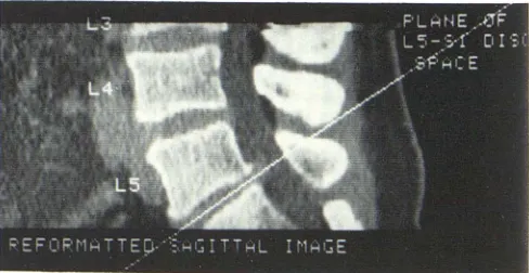
Fig. 5.-Reformatted sagittal image of L5-S1 level has electronic linE
[image:2.612.53.295.87.222.2] [image:2.612.316.557.90.284.2] [image:2.612.54.295.290.484.2] [image:2.612.317.556.350.519.2] [image:2.612.316.560.585.711.2]AJNR: 1, November IDecember 1980 CT OF LUMBOSACRAL SPINE 553
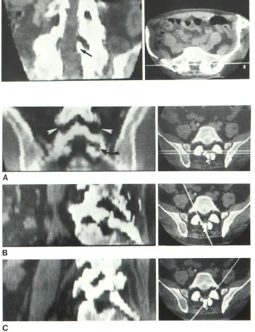
Fig. 6.- A, Metrizamide myelogram. Defect (arrow) along the posterior aspect of neural canal at L4. B, Axial CT image taken through L4-L5 disc. Displaced
bone fragment (arrow) within neural canal. Patienl
was prone. C, Reformatted tilted sagittal image. Bone fragment within neural canal.
Materials and Methods
All 269 scans were performed with a GE CT IT 8800. A 25 cm
algorithm was used for detail. Scanning details were: speed, 9.6
sec; 120 kVp; 760 mAs; and 1.5-or 5-mm-thick slices.
The patient is placed supine on the table. The hips are flexed and the knees supported with pillows to reduce the lumbar lordotic curves. The patient's hands are placed on the chest or under the
head. A lateral digital radiograph is taken and used to determine
necessary gantry angulation and scan positions. Then, 1.5-mm
-thick axial scans are taken parallel to the individual vertebral bodies
and the intervertebral disc spaces.
If the inclination of any intervertebral body or disc space exceeds
the limitations of gantry tilt (fig. 2), or when there is a lateral vertebral tilt, that region is scanned with the gantry in a neutral
(vertical) position in preparation for later image reformatting. Axial
slices 5 mm thick are taken at 5 mm intervals (fig. 3). Scans are not overlapped. About six slices are adequate for examination of L5
-S1, or 10 slices for L4-S1. The examination takes about 30 min. At this point the patient may leave, and the image can be formatted
later.
Overlapping 5 mm sections at 2.5 mm intervals improves image
quality; however, this has the undesirable effects of both higher
patient radiation dose and a lengthier examination period. Slices
1.5 mm thick each taken at 2 mm intervals seem promising for
future evaluation, as it would reduce patient radiation (fig. 4).
c
A reformatted image plane with dorsoventral tilt is generated as
follows. The reformatting program is invoked and the computer instructed to display several (up to four) of the axial slices from the
original study. Using a trackball positioned cursor, a line is drawn
on one of the images in a true sagittal plane in the patient's spine. The equivalent line appears on all the displayed images. The com
-puter program is then instructed to reformat the stored display data
into the sagittal plane which includes the electronic line and is also
perpendicular to the axial plane. Next, a second line is electronically
drawn on the sagittal image through the disc space to be examined
(fig. 5), and the computer program is instructed to reformat the
stored display data into the plane which is both perpendicular to
the true sagittal image and also includes the new electronic line.
Mediolaterally tilted image planes are defined in a similar manner.
The second reformatting operation is carried out by defining a line on a true coronal image.
Coronal, sagittal, or oblique image planes can be specified to the
computer program by either of two techniques. The starting point
for both is the simultaneous display of three axial images. In one
technique, the trackball cursor is used to define three points, one in each of the three axial images. These three points are mat
he-matically sufficient to define a plane. For the second technique, a
point and a line are respectively defined in two of the axial images
in planes defined by either technique.
554 HIRSCHY ET AL. AJNR:1, November/December 1980
A
B
c
range 1 -250 pixels (pixel size is 0.8 mm). All computations are performed using the computer system supplied with the scanner.
Reformatting multiplanar images is done while "off-line" because the reconstruction process cannot be performed while patients are being scanned. The procedure is performed by the physician with-out assistance from the technologist. The time required to reformat
the images varies with the thickness of the desired reformatted
image, and with the number of rotated or tilted reformatted planes. A simple nontilted coronal or sagittal plane that is one pixel thick takes about 10 to 15 sec of computer time. Tilting the image in one plane increases computer time to about 20 sec while biplane tilt takes about 30 sec. Increasing the width of the reformatted image to 2 pixels doubles the time necessary for the reconstruction.
Further increase in pixel width proportionately increases reco
n-Fig. 7.-Reformatted coronal image
of lumbar spine. Bone spur (arrow) and displacement of dura. No evidence of bone disruption in lateral spinal fusion.
Fig. 8.- A, Reformatted tilted coronal image. Spinal fusion at L4-L5 (ar
row-heads) is disrupted bilaterally. Fusion at L5-S1 (arrow) is also disrupted. Right (B) and left (C) tilted oblique views refor-matted through lamina. Bilateral disrup-tions of ununited spinal fusion.
struction time. With the initial scanning time of 1 5-20 min including setting up the patient and preparing the computer, a patient is scheduled every 30 min. Five separate reformatted images, two angles of coronal, two different pixel widths of sagittal, plus a reformatted axial image at L5-S1 seems to be adequate for a total spine study. The reconstruction time with doctors' input is about 5-7 min. The reformattting is done immediately after the scan, or if time does not permit, at the next break or at the end of the day. The total time for scanning, reformatting, and filming is about 30 min.
Representative Case Reports
[image:4.612.51.424.90.575.2]AJNR:1 , November/December 1980 CT OF LUMBOSACRAL SPINE 555
A
B
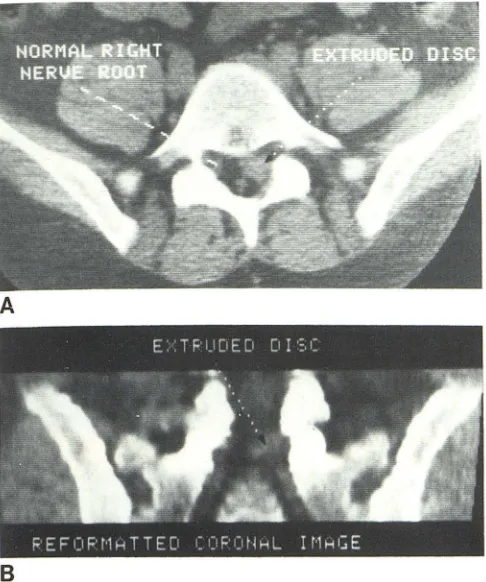
Fig. 9.-A, Direct axial CT image through L5-S1 level. Herniated nucleus pulposus obliterates nerve root (arrow). B, Reformatted tilted coronal view
through lower dura and nerve roots confirms extruded disc (arrow).
Case 1
A 32-year-old woman had bilateral Harrington rods placed from 05 to L2 on the left, and from 07 to L4 on the right to correct a
lumbar scoliosis. After the procedure, low back pain developed and
it was discovered by standard radiographs that the right Harrington
rod had broken through the posterior lamina of L4. The rod
respon-sible for the fracture was then surgically removed, but the localized
low back pain persisted at the L4 level. Myelograms were
sugges-tive but not conclusive for an extradural defect at L4 (fig. 6A), and
the patient was referred for a CT scan. The patient's scoliosis and
pain prevented her from lying flat on the table. Computed
tomog-raphy with axial slices (fig. 68) and sagittal reformatting showed
that there was a bone fracture of the lamina of L4 which was displaced into the neural canal. Reformatting with mediolateral and dorsoventral tilt was necessary to best visualize the neural canal
and bone fragments without distortion (fig. 6C).
Case 2
A 38-year-old man with an old spinal fusion and persistent back pain was referred for CT evaluation. The examination was to
ascer-tain whether the fusion was solid and/or whether there was another
cause for his persistent neuralgia. Dorsoventral reformatting was
done in order to correct for the lumbar lordosis. The reformatted
images showed that the fusion was solid. They also demonstrated
a bone spur arising from the spinal fusion projecting into the neural
canal. The spur was displacing and deviating the dural sac and the
neural roots (fig. 7).
Case 3
A 47-year-old man with a spinal fusion from L3 to S 1, and
persistent back pain after surgery was referred for CT evaluation. The autograft was identified on the axial slices, but it could not be determined whether the fusion was solid. There was evidence of a mild spinal stenosis secondary to facet joint hypertrophy. Without
rescanning, the area of the spinal fusion was reformatted and the
coronal plane was displayed. The coronal plane view permits visu -alization of the entire area of spinal fusion on one plane, permitting distinction between undulation of the fusion bone and gaps indi cat-ing nonfusion. The posterior and lateral elements from L3 to S1
were examined by tilting the coronal plane in the dorsoventral
direction to compensate for lordosis. The coronal reformattting
demonstrated that there was a disruption of the fusion at both the
L3-L4 and L4-L5 levels (fig. 8A). Oblique reformatting confirmed
the diagnosis (figs. 88 and 8C).
Case 4
A 44-year-old man with left sciatic nerve pain was suspected to
have a herniated disc. The CT study with axial slices showed that
there was degeneration of the L4-L5 disc and herniation of the
nucleus pulposus on the left side at L5-S1 (fig. 9A). Using lateral tilt and dorsoventral angulation, the initial study was reformatted in the coronal plane. The reformatted image showed a soft-tissue
mass at the intervertebral disc space which obliterated the nerve roots on the left at L5-S1. Although the diagnosis was possible on the axial projections, the ability to see the lesion in two planes made the diagnosis more secure (fig. 98).
Case 5
A 49-year-old man was referred for CT evaluation of low back
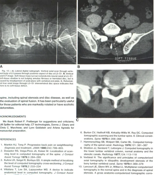
pain. Axial slices suggested an extruded disc at the L5-S1 (figs. 10A and 10B). Reformatting a true axial plane through the L5-S1 intervertebral disc space showed that the dural sac was normal and that there was no evidence of a herniated disc (fig. 10C).
Discussion
Until recently, CT of the spine, especially in the lumbar region, has been limited in its usefulness by uncertainty about the exact location of an axial slice in the spine, the inability to angle the scanning gantry perpendicular to the long axis of the neural canal, the partial-volume effects with thick slices, and the difficulties encountered in patients with
a scoliosis or lumbar lordosis. Digital radiography allows
proper positioning. A new computer program permits
refor-matting of images in mediolateral tilt plus dorsoventral tilt
and also reformatting of axial images through areas that
exceed the mechanical limitations of gantry tilt.
These reformatting procedures have been found
[image:5.612.53.296.91.382.2]556
HIRSCHY ET AL. AJNR:1, November/December 1980A
Fig. 10.- A, Lateral digital radiograph. Vertical axial scan through vert e-bral body of LS passes through posterior aspect of disc at LS-S1 . B, Vertical axiat CT image. Soft-tissue mass (arrow) extends into neural canal at LS-S1. Soft-tissue shadow is not bulging annulus fibrosus or herniated disc, but is caused by misalignment of axial plane with vertebral end plate. C, Reformat-t d true axial image through LS-S 1 intervertebral disc space indicates that there is no soft-tissue defect.
spine, including spinal stenosis and disc disease, as well as
the evaluation of spinal fusion. It has been particularly useful
for those patients who are markedly rotated or have scoliotic
deformities.
ACKNOWLEDGMENTS
We thank Robert F. Freiberger for suggestions and criticisms;
Jill Spiller for editorial help; CT technologists, Donna J. Cleary and
Chris C. Marchese; and Lynn Goldstein and Arlene Agresta for
manuscript preparation.
REFERENCES
1. Mankin HJ, Teng P. Progressive back pain on weightbearing: diagnosis and treatment. JAMA 1980;243: 799-803. 2. Dossetor RS, Veiga-Pires JA, Kaiser M. Localization of sca
n-ning level in computed tomography of the spine. J Comput
Assist Tomogr 1979;3: 284-285
3. Kuhns LR, Seigel R, Borlaya GS. A simple method of localizing the level of computed tomography cross-sectioning. J Comput
Assist Tomogr 1978;2: 233-234
4. Villafana T, Lee SA, Lapayowker MS. A device to indicate
anatomical level in computed tomography. J Comput Assist
Tomogr 1978;2:368-371
5. Williams AL, Haughton VM, Syvertsen A. Computed tomogra -phy in the diagnosis of herniated nucleus pulposus. Radiology
1980;135:95-99
B
C
6. Burton CV, Heithoff KB, Kirkaldy-Willis W, Ray DC. Computed
tomographic scanning and the lumbar spine. II. Clinical consid
-erations. Spine 1979;4: 356-368
7. Hammerschlag SB, Wolpert SM, Carter BL. Computed
tomog-raphy of the spinal canal. Radiology 1976;121 : 361-367
8. Sheldon JJ, Sersland T, Leborgne J. Computed tomography in the lower lumbar vertebral column, normal anatomy and the stenotic canals. Radiology 1977; 124: 113-118
9. Verbiest H. The significance and principles of computerized
axial tomography in idiopathic development stenosis of the
bony lumbar vertebral canal. Spine 1979;4: 369-378 10. Lancourt JE, Glenn WV Jr, Wiltse LL. Multiplanar computerized
tomography in the normal spine and in the diagnosis of spinal stenosis. A gross anatomic-computerized tomographic corre
-lation. Spine 1979;4:379-390
11. Glenn WV Jr, Rhodes ML, Altschuler EM, Wiltse LL, Kostanek
C, Kuo YM. Multiplanar display computerized body tomography
[image:6.612.55.562.111.682.2]