Autonomous Model Building Using Vision and
Manipulation
A thesis submitted in partial fulfilment of the requirements of the
University of the West of England, Bristol for the degree of Doctor
of Philosophy
Author:
Alan B
ROUNSupervisors:
Prof. Tony P
IPEProf. Majid M
IRMEHDIProf. Chris M
ELHUISHJanuary 3, 2016
Abstract
Robotic systems often require models in order to successfully control themselves, and to interact with the world. Models take many forms and include kinematic models to plan motions, dynamics models to control forces, and models of 3D geometry to check for collisions, to name but a few. Traditionally, models are provided to the robotic system by the designers that build the system. However for long-term autonomy, it becomes important for the robot to be able to build and maintain models of itself, and of objects it might encounter.
This thesis advances and explores the argument for enabling robotic systems to autonomously build such models, and the main contribution of this research is to show how a layered approach can be taken to building these models. To begin with a system is presented which enables a robot starting with a limited amount of information to first build a Surfel based model of its hand using the Iterative Closest Point (ICP) algorithm. The system is then able to use the hand model and the ICP algorithm to track the movement of the hand in order to autonomously construct a kinematic model which describes the robot’s body. This kinematic model can in turn be used to plan and perform future movements.
Key to the incremental, autonomous approach is the use of exploratory actions. These are actions that the robot can perform in order to gain information, either about itself, or about an object with which it is interacting. Another contribution is the presentation of a method whereby a robot, after being powered on, can use exploratory actions to home its joints using just vision, i.e. traditional methods such as absolute encoders, or limit switches are not required.
The next contribution of this research is to look beyond the robot’s body and to present methods with which a robot can autonomously build models of objects in the world around it. The first class of objects examined are flat pack cardboard boxes, a class of articulated objects with a number of interesting properties. It is shown how exploratory actions can be used to build an edge based model of a flat pack cardboard box and to locate any hinges the box may have. Specifically, it is shown how when interacting with an object, a robot can combine haptic feedback from force sensors, with visual feedback from an edge based tracking system to get more information from an object than would be possible using just a single sensor modality.
Acknowledgements
The journey involved in studying for a PhD and in writing up this thesis has been long and arduous, and I could not have made this journey without the help of many different people. Firstly, thank you to my supervisor Tony Pipe for helping me to find my thesis topic and for providing much useful advice along the way. The Leverhulme Trust, provided financial support for this work, and funded my PhD under project number F/00182/CI, and for this I am very grateful. Thank you also to my PhD partner Chris Beck, who has been a true friend over the years, and someone with whom I can commiserate with on the stress of PhD work, and on the woes of robotics research. We did not quite achieve our initial plan of completing a PhD in 3 weeks, but occasions such as trying to wrestle robots into submission at 3am in a German hotel room, have made the whole process very memorable, and great fun.
Thank you to Majid Mirmehdi for the many hours spent reading and suggesting corrections to my papers, they benefited immensely from your input. Thank you to Chris Melhuish, head of the BRL, for inspiration, keeping the lights on and also for the upgrade to the labs midway through my PhD, which made working conditions immeasurably more comfortable. Thank you to Tom Rooney, for diverting me with talk of whiskers and underwater robotics, and for showing me the vast number of uses for Gaffa tape. Thank you to Ian Horsfield and the rest of the technicians in the lab for all your help, and for your patience with me as I advanced from my previous life as a software engineer to becoming a bit more practical. Also, thank you to Matt Studley, who is always a great person to bounce ideas off and a continuing source of advice and inspiration.
Contents
Contents 1
List of Figures 4
List of Symbols 8
Glossary 12
1 Introduction 15
1.1 Motivation . . . 15
1.1.1 Model Based Robotics . . . 16
1.1.2 Behavioural Robotics . . . 17
1.1.3 Autonomous Model Building . . . 19
1.2 Thesis Overview . . . 21
1.2.1 Aims and Objectives . . . 21
1.2.2 Contributions . . . 22
1.2.3 Outline . . . 23
2 Background and Existing Work 24 2.1 Models Within Biological Systems . . . 25
2.1.1 Body Schema and Body Image . . . 25
2.1.2 Internal Models for Motor Control . . . 26
2.2 Calibration of Kinematic Models . . . 26
2.3 Building Models of Robotic Systems . . . 28
2.4 Object Models . . . 30
2.5 Relevance to Thesis . . . 31
3 Robotic Platform 32 3.1 Hardware Description . . . 32
3.2 Developed Control Software . . . 34
3.2.2 Software Developed for the Baxter Robot . . . 36
3.2.3 Other Software Developed for the Robots . . . 37
3.3 Evaluating Accuracy and Repeatability . . . 37
3.3.1 Accuracy and Repeatability of the BERT Robot . . . 38
3.3.2 Accuracy and Repeatability of the Baxter Robot . . . 40
3.3.3 Discussion . . . 41
3.4 Controlling the Movement of the Robots . . . 42
4 Autonomously Building Models of the Robot’s Arm 43 4.1 Background and Related Work . . . 44
4.1.1 Exploratory Motion and Active Vision . . . 44
4.1.2 Object Modelling and Tracking . . . 45
4.1.3 Kinematic Identification . . . 45
4.2 Method . . . 46
4.2.1 Finding the Hand . . . 47
4.2.2 Centring the Hand . . . 52
4.2.3 Building a Model of the Hand . . . 53
4.2.3.1 Point Cloud Alignment with ICP . . . 55
4.2.3.2 Updating the Surfel Model . . . 56
4.2.3.3 Tracking the Hand . . . 57
4.2.4 Building a Kinematic Model . . . 59
4.2.4.1 Constructing a Screw Transformation . . . 60
4.2.4.2 Obtaining the Screw Decomposition . . . 61
4.2.4.3 Constructing the Kinematic Model . . . 63
4.3 Validating the System . . . 64
4.3.1 Hand Location and Centring . . . 64
4.3.2 Hand Tracking Accuracy and Precision . . . 65
4.3.3 Assessing the Hand Model . . . 66
4.3.4 Assessing the Kinematic Model . . . 67
4.4 Summary . . . 68
5 Visual Homing 71 5.1 Visual Homing . . . 73
5.1.1 The Exploratory Joint Space . . . 74
5.1.2 Homing the Neck Joints . . . 75
5.1.3 Making the Hand Visible . . . 76
5.1.4 Finding the Hand . . . 78
5.1.5 Locating Joint Axes . . . 78
5.1.6 Kinematic Calibration . . . 79
5.2 Experiments . . . 80
6 Hinge Exploration for Building Articulated Object Models 85
6.1 Building Articulated Models of Flat Pack Cardboard Boxes . . . . 86
6.2 Background and Related Work . . . 88
6.3 Robotic Platform . . . 88
6.4 Method . . . 90
6.4.1 Representing the Cardboard Box Model . . . 92
6.4.2 Visually Tracking the Box Model . . . 92
6.4.2.1 Camera Model . . . 93
6.4.2.2 Evaluating Box States with a Fitness Function . 94 6.4.2.3 Frame to Frame Tracking . . . 97
6.4.3 Initialising Tracking . . . 98
6.4.4 Autonomously Building a Cardboard Box Model . . . 99
6.4.4.1 Identifying Potential Hinges . . . 99
6.4.4.2 Testing Potential Hinges . . . 100
6.4.4.3 Haptic Evaluation . . . 102
6.4.4.4 Visual Evaluation and Refining the Location of a Hinge . . . 104
6.5 Experimental Evaluation . . . 105
6.6 Summary . . . 108
7 Object Text Models 109 7.1 Background and Related Work . . . 110
7.2 Overview of Application . . . 111
7.3 Methods . . . 113
7.3.1 Exploration Process . . . 113
7.3.1.1 Object Filtering . . . 113
7.3.1.2 Gaze Control . . . 114
7.3.1.3 Text Detection and Recognition . . . 115
7.3.2 Search Strategies . . . 115
7.3.2.1 Preprogrammed Poses . . . 115
7.3.2.2 Planar Alignment . . . 116
7.3.2.3 Text Centring and Zooming . . . 117
7.4 Experiments . . . 119
7.5 Summary . . . 122
8 Conclusion 123 8.1 Thesis Summary . . . 123
8.2 Contributions . . . 124
8.3 Future Work . . . 125
List of Figures
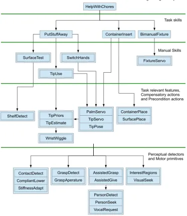
1.1 An example of how a complex task such as ‘help with chores’ was programmed for the Domo robot (Edsinger (2007)) by
hierarchically composing simpler tasks. . . 18
1.2 Chain of dependencies which shows how a robot with a model of its hand is able to perform actions which allow it to build a kinematic model of its body and then ultimately pick up an object . . . 20
2.1 A Smith predictor is a controller that makes use of an internal model of a controlled system, and a model of the delays within that system in order to provide good control. Miall et al. (1993) propose that the cerebellum may use something similar to Smith predictors. . . 26
3.1 The BERT robot examining its hand. . . 33
3.2 The Rethink Robotics Baxter research robot. . . 33
3.3 The hardware and software systems used to control BERT. . . 34
3.4 This graph showing the nodes (processes) running for a hand tracking program, developed by the author, used for part of the work presented in Chapter 4. The directed edges between nodes represent communication channels, with /tf for example representing 3D transformation data, and /rosout representing status output from each of the nodes. . . 36
3.5 The possible combinations of accuracy and repeatability. . . 38
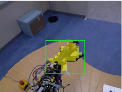
4.2 An example of performing NCC on the input signal and on optical flow from an 8x8 block of the camera image that contains the hand. NCC is repeatedly applied to compare the output signal to delayed versions of the input signal, with each application giving a point on the Cross Correlation line. . . 50 4.3 Typical output from the wave detection process. The regions in
yellow represent blocks where the NCC response was above a preset thresholdλhand. . . 51 4.4 A 3D model is formed from a collection of surfels. . . 53 4.5 Points not part of the hand are filtered out with a box that moves
with the tracked model. . . 54 4.6 A surfel model obtained by aligning, and merging, multiple point
clouds. . . 58 4.7 The effect of varyingdmaxandϕmodel. Subfigures a) to c) show that
asϕmodelthe angle between model updates is increased, the number of surfels used in the model decreases. Eventually ifϕmodelgets too high, then interframe tracking of the hand will fail. Subfigures d) to f) show how varyingdmax can affect the quality of the produced model. Subfigure d) (highlighted in blue) show the parameters that subjectively gave the best models. . . 59 4.8 Screw decomposition of a Euclidean transformation. . . 60 4.9 A point on the intersection of the bisecting planes is used forso. . 62
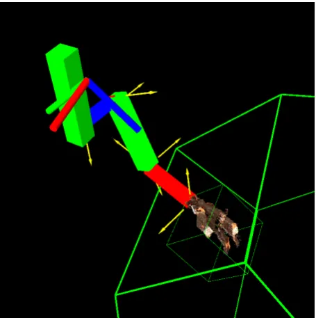
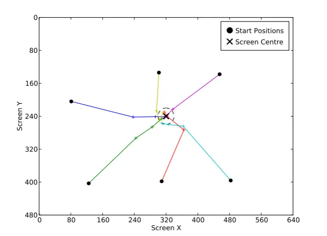
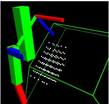
4.10 The constructed kinematic model and hand model in camera space. The yellow arrows represent the estimated joint axes used to construct the model. . . 63 4.11 The result of running the visual servoing procedure for 3 steps from
6 different starting points. . . 64 4.12 The grid of test points used for assessing precision. . . 65 4.13 A higher resolution model of the hand captured with a 3dMD scanner. 67 4.14 Error histograms showing the distribution of absolute errors in
5.3 The coloured points in this image show the position of the wrist in camera space for 50,000 random positions in joint space. The green camera frustum represents the space viewable by the camera, and it can be seen that the majority of possible wrist poses fall outside this frustum (and will therefore not be visible). . . 76 5.4 The effect of varying the number of measured wrist poses in
simulation. Different lines reflect the results that were obtained for different levels of zero mean Gaussian noise, added to the simulated measurements of the wrist frames position and orientation. These are the results for homing the entire skeleton (including neck joints) by locating the hand. . . 81 5.5 Also showing results from simulation - much better results were
obtained when the neck joints were homed separately before attempting to home the rest of the skeleton. . . 82 6.1 The Baxter robot used for this work. A vacuum gripper on the left
arm is used to move the box, the right arm is used to try to bend hinges, and the camera mounted to the front of the robot observes the hinge bend motion. . . 90 6.2 The process used to autonomously build a box model. . . 91 6.3 An example of how edge points and hinges form a box model, and
how the coordinate frames of each face are positioned. For clarity, only a few elements of each type are labelled. . . 93 6.4 The process used to match model edge points, projected into image
space with edge pixels. . . 95 6.5 A typical set of internal and external sample points used to build
histograms of the colour inside and outside of the box model when projected into image space (some sample points have been omitted for clarity). . . 96 6.6 The measured box pose is shown in green, and the potential hinge
is shown in orange. The ideal hinge position (shown in red) is defined when setting up the system and allows the ideal pose of the box (shown in blue) to be calculated. . . 101 6.7 The effort exerted by the right end effector as the exploratory hinge
move is made is compared to a pre-recorded baseline effort profile in order to determine the presence or absence of a hinge. . . 103 6.8 The boxes used in the experiments. Hinges have been marked with
dashed lines. . . 106 6.9 Internal edges are those which cannot deduced from the outline of
7.1 The BERT robot with added high resolution camera. . . 112 7.2 The exploration process used to read text from an object. . . 113 7.3 By combining a depth filter, a kinematic model of the robot, and
a model of the robot’s hand, the point cloud from the Kinect is filtered to leave just the object. . . 114 7.4 The TCZ strategy in action - the top image shows the text
List of Symbols
A wave amplitude.
Q a set of quadrilaterals.
Z a set of zoom levels.
[ˆs]× skew symmetric matrix.
Ψ set of exploratory poses. α a homing offset angle.
β angle between Kinect camera axis and the instantaneous velocity vector at an
observed point.
˙
θ acceleration in joint space.
ψ exploratory pose.
θ position in joint space, a vector of joint angles.
εhand threshold used when centring robot’s hand.
η(i) a surfel indicator function.
γ wrist actuator angle.
ˆ
φ visual homing measured exploratory angle. λdepth depth threshold used in Chapter 7.
λhand threshold used to detect a robot’s hand.
λmodel model distance threshold used in Chapter 7.
E Euclidean transformation matrix.
Gi SE(3)generator matrix.
I identity matrix.
J(θ) joint Jacobian matrix.
K intrinsic camera matrix.
M interframe motion transformation matrix.
R rotation matrix.
T transformation matrix.
˙x acceleration in Cartesian space.
ˆn(ei) edge point normal.
ˆn(pi) point normal.
ˆn(si) surfel normal.
ˆnimage Kinect image plane normal.
ˆs screw axis normal.
b the state of a flat pack cardboard box.
o a homing offset.
so point on a screw axis.
v(ei) edge point position.
v(pi) point position.
v(si) surfel position.
x position in Cartesian space. E a set of edge points.
S a surfel model. ei an edge point. fi a box face. hi a box hinge.
pi a point from a point cloud. si a surfel.
m(i) a surfel matching function. B cardboard box model histogram.
C calibration index for a kinematic calibration method. E cardboard box external colour histogram.
H a histogram.
I cardboard box internal colour histogram. M mobility index.
S number of sensed joints.
E an edge image.
I image from a camera.
ω angular velocity.
φ visual homing exploratory angle. π pi.
ρ(X,Y) correlation coefficient between two random processes.
θ rotation angle.
ϕmodel surfel model update angle.
c(pi) point colour.
c(si) surfel colour.
dmax distance threshold used when building surfel models.
f wave frequency.
k constant gain.
l focal length.
q a quadrilateral.
r(si) surfel radius.
r distance of point from actuator axis.
t time.
vimage linear velocity on image plane.
v linear velocity.
Glossary
active computer vision refers to a computer vision system that can change the viewing parameters of the camera (such as its position, or zoom level for example) in order get more information from the observed scene.
Augmented Reality (AR) marker a computer generated marker, designed so that its position and orientation can be easily and reliably estimated using computer vision algorithms.
Bayesian network a probabilistic graphical model that uses a directed acyclic graph to represent random variables and their dependencies.
BERT Bristol and Elumotion Robotic Torso - an upper torso humanoid robot used in this work.
block matching algorithm an algorithm that estimates the movement of small blocks (typically 8x8 or 16x16 pixels) between consecutive video frames.
body schema a sensory and motor systems representation of the body, that is used for performing actions.
CAN Controller Area Network - a communication bus standard commonly used in automation and robotics.
closed world assumption a simplifying assumption made about some robotic systems that the internal models used by the robot are complete, and contain everything about the world that the robot needs to know.
CMM Coordinate Measuring Machine - a device for performing precision 3D measurements.
exploratory action an action taken by a robot to try to extract information about itself, its environment, or about an object it is interacting with.
IBVS Image Based Visual Servoing - a technique whereby visual feedback from a camera is used to control the motion of a robot.
ICP Iterative Closest Point - an algorithm for aligning point clouds.
internal model an abstract computer model describing some aspect of the robot, the environment the robot operates in, or an object in the environment. Used to allow the robot to reason about the world and to plan actions.
kinematic calibration the process of refining an existing kinematic model so that it better describes the movement of a robotic system.
kinematic identification the process of building a kinematic model for a robotic system.
kinematic model a model that mathematically describes a robot’s motion without considering the forces that affect the motion.
lazy learning methods methods for machine learning that delay the task of generalising from their training data.
LWPR Locally Weighted Projection Regression - a lazy learning method that performs linear regression using training samples close to the input to predict an output.
motor babbling a series of random motor commands often used with machine learning to learn about a robotic system.
MSER Maximally Stable Extremal Regions - a technique for detecting blobs in images.
OCR Optical Character Recognition - a technique which can extract text from images.
optical flow a 2D vector field describing the apparent motion seen between camera image frames as the camera moves relative to the environment or objects in the environment.
ROS Robot Operating System - an open source set of software libraries designed to aid in the writing of distributed robotic software.
SEA Series Elastic Actuator - a compliant actuator formed by inserting a spring element between the gearbox and the load.
SLAM Simultaneous Localization and Mapping - a technique whereby the location of a robot within a map is estimated, at the same time that the map is being constructed.
Smith predictor a predictive controller that makes use of an internal model of a controlled system, and a model of the delays within that system in order to control the system.
Chapter 1
Introduction
In modern robotic systems, models are often used to help control the robot, and to help the robot to interact with the world. For example, a robot may have kinematic and dynamic models of its body to help it plan motions, and 3D models of its body parts to check motion plans for potential collisions. The robot may also have models of its environment and the objects around it.
In a lot of systems, these models are provided by the system designers. This approach works well for fixed systems working in a known environment, but can face problems if the robot encounters unfamiliar objects, if its body degrades, or if its body is modified by a user.
This thesis looks at using active computer vision, and exploratory actions in order to enable a robot to progressively build a series of internal models. It starts by looking at how a robot can build models of itself, and then extends this work to show how a robot can build models of objects that it encounters in its environment. In particular, emphasis is placed on how interacting with an object can give a robot more information for building a model than it would be able to obtain by just passively observing the object.
1.1
Motivation
To put the problem which this thesis tries to tackle into some kind of context, consider the situation where a robot with one or more arms is switched on, and the goal is to try to get it to pick up and identify an object in front of it.
where repetitive actions are performed on identical objects. It is also easy to see however that because of its inflexibility, it is not a suitable way to provide a robot with the ability to manipulate unfamiliar objects in arbitrary poses.
1.1.1
Model Based Robotics
One way to introduce more flexibility into the system is to use a model based approach (also called a sense-plan-act approach) to design the robotic system. Here the robot maintains one or more models of itself, its environment, and the object it is trying to manipulate. The robot uses sensors to try to determine as well as possible the current state of the world, and to try to define the world state in terms of the available models it has. With its estimate of the world state, the robot plans its actions and then attempts to execute them by moving its actuators. The models provide an advantage over simply using raw sensor data to plan actions, as they help to provide much more information about the state of the world.
Many robotic systems presented in the literature make use of models in their operation. Two examples which illustrate well the way in which internal models can help a robotic system interact with the world are the ARMAR-III robot (Asfour et al. 2006) and the work of Scholz et al. (2011). The ARMAR-III robot is a recent robotic system that has used pre-built 3D models of objects in order to aid its perception system in the task of identifying objects and estimating their position and orientation in 3D space. Scholz et al. (2011) equip a PR2 robot with a model of a small cart and thus enable the PR2 to navigate around an office environment whilst pushing the cart.
Often, the models that the robotic system uses to plan its actions are created for it by human operators, with models of the robot and the objects it manipulates, being derived from CAD models. A key problem with this approach detailed by Murphy (2000) is the closed world assumption. The closed world assumption assumes that the models are complete, and contain everything about the world that the robot needs to know. If the robot encounters a new object that it does not have a model for, or if one of its existing models turns out to be inaccurate, then the plans that the robot creates for manipulating objects may fail and cause damage to both the environment and the robot.
1.1.2
Behavioural Robotics
Before continuing down the path of building and maintaining models, it is important to be aware of a more radical approach to the problem of having incomplete or inaccurate models. Behavioural robotics as popularised by Brooks (1991), argues that maintaining models of the world and the robot is unnecessary, and that intelligent and useful behaviour can be obtained from a robot by grounding its actions in the real world. The principle is that ideally, actions should be directly linked to sensor inputs. The aim is to allow the robot to use the world itself as a model, and this is certainly appealing as the world is always up to date and correct.
HelpWithChores
BimanualFixture ContainerInsert
PutStuffAway
SurfaceTest SwitchHands
FixtureServo
TipUse
ShelfDetect TipPriors
TipEstimate
WristWiggle
PalmServo
TipServo
TipPose
SurfacePlace ContainerPlace
ContactDetect
StiffnessAdapt
CompliantLower GraspAperature GraspDetect
VocalRequest PersonSeek PersonDetect AssistedGrasp
AssistedGive VisualSeek
InterestRegions
Single integrated system
Task skills
Manual Skills
Task relevant features, Compensatory actions and Precondition actions
[image:21.595.140.514.153.585.2]Perceptual detectors and Motor primitives
Figure 1.1: An example of how a complex task such as ‘help with chores’ was programmed for the Domo robot (Edsinger (2007)) by hierarchically composing simpler tasks.
model is used to provide predictions for where the robot’s hands will appear in camera space. Therefore this thesis argues, that even if they are implicit in the implementation of a system, models are important to allow a robot to perform a variety of high level tasks. Furthermore this thesis also argues, that making models explicit offers certain advantages in that they become easier to reason about, and thus decouple from the rest of the robotic system.
1.1.3
Autonomous Model Building
Accepting that models are important for enabling robots to plan and perform a wide range of actions in unstructured environments, the focus of this research is therefore on getting a robot to automatically build models of both itself and of objects of interest. With these models the robot should be able to plan and execute actions that move its body, and then successfully manipulate the objects. The aim is to enable a robot to cope with the two problems of encountering unfamiliar objects, and of its existing models becoming too inaccurate to be useful.
It is interesting to consider both the order in which models should be constructed, and the order in which they can be constructed. Models as well as being seen as a representation of some aspect of the world, can also be seen as enabling artefacts which can improve a robot’s performance in some actions, or even allow it to perform new actions that it was unable to perform before. Being able to perform some new action may in turn enable the robot to build a new type of model, allowing knowledge and competence to be built up progressively.
As an example, consider the problem of trying to pick up a cup. If the robot does not know where its hand is, then it will be almost impossible for it to pick the cup up safely. Therefore a kinematic model describing how the robot’s hand relates to its vision system, becomes very useful for the robot as it would enable, or at least greatly assist, the robot to position its hand to pick up the cup. Now, in keeping with the theme of autonomous model building, the kinematic model should be constructed by the robot itself. One method for doing this could be to first have the robot track the movement of its hand with its camera. The robot could then use the tracked movements to infer the dimensions of its arm, and the position of the joints that come between the vision system and the hand.
Hand Model
Kinematic Model
Position Hand With IK
Grasp Object Track Hand
Model
Build Kinematic Model
Model
Action Key:
Figure 1.2: Chain of dependencies which shows how a robot with a model of its hand is able to perform actions which allow it to build a kinematic model of its body and then ultimately pick up an object
once the robot can pick up the cup, it can examine it more closely and build a model of it. This is not to say that the robot would not be able to start to build a model describing the cup before it picks it up, but being able to pick up and manipulate the cup, offers the chance to obtain a lot more information about the cup than would be possible from a purely passive observation. For example, whilst manipulating a bottle the robot may discover that the bottle has a cap, which can be twisted off. Perhaps if the robot is equipped with a text reading system it may be able to discover that the bottle contains water. This is all information that could be added to a model of the bottle. Also this extra information may suggest other actions, such as pouring a drink, which could be performed with the bottle.
The chain of actions and models can also be extended backwards in the sense that the model of the hand must come from somewhere, and so it is possible to look for actions that the robot can perform in order to autonomously build the model. These actions may in turn require further models, or it may be possible to implement the actions as purely reactive behaviours.
in the effort to increase long term autonomy for robots.
1.2
Thesis Overview
This thesis attempts to tackle the problem of enabling a robot to autonomously build models of itself and of objects around it by using vision and manipulation. In particular
• it proposes that a layered approach to model building will allow a robot to proceed progressively from a state of very little knowledge, to having rich representations of itself, and objects in the world.
• it proposes that an active approach to learning, whereby a robot gains information by performing exploratory actions, provides an effective way of obtaining information for building models.
1.2.1
Aims and Objectives
To support the hypotheses set out above, the aim of this work is to build a series of systems that allow a robot to build models of itself, and models of objects in the world around it. Specific objectives of this work are
• to create a system that allows a robot to progressively build models that describe the physical dimensions and kinematics of its hand and arm.
• to extend the system so that the robot can build models of objects in the world around it.
• to explore the use of exploratory actions as a means of enabling a robot to gain information about itself, or about an object it is examining.
1.2.2
Contributions
The main contributions of this thesis, along with the chapters in which they can be found are as follows:
• A method for enabling a robotic system to build a kinematic model of itself using a series of exploratory actions is described and evaluated. It is shown how the robotic system can start with a very limited amount of information, and then use exploratory actions to gather information about its body via its visual (depth camera) and proprioceptive systems. As far as the author is aware this is the first markerless system that allows a robot to build a kinematic model of itself with a depth camera. (Chapter 4)
• A novel method is presented that makes use of vision in order to home the joints of a robot when it is powered on. This method reduces the need for traditional methods of homing a robot, such as absolute encoders, or limit switches, and so offers the possibility of building cheaper and more reliable robotic systems. (Chapter 5)
• In the context of visual homing, the concept of an exploratory joint space that a robot may safely move in whilst attempting to home itself is described. This new concept is important for ensuring that robots can visually home themselves without damaging themselves. (Chapter 5)
• A novel edge based tracker is presented that incorporates colour cues and can be used to track the motion of articulated flat pack cardboard boxes. (Chapter 6)
• A hinge exploration strategy that combines both visual and haptic feedback in order to evaluate the presence or absence of a hinge is described and evaluated. (Chapter 6)
• A novel robotic text reading system is described, which makes use of exploratory actions in order to find and read any text which may be on an object. This system, to the best of the author’s knowledge, is the first system that attempts to give to a robot the general purpose skill of reading an object in its hand, in a form that would be recognisable to a human. (Chapter 7) Much of the work in this thesis has been presented separately as conference or journal papers, with the work for these papers being done by the author of this thesis.
• Alan Broun, Chris Beck, Tony Pipe, Majid Mirmehdi, and Chris Melhuish (2014a). Bootstrapping a robot’s kinematic model. In: Robotics and Autonomous Systems62.3, pp. 330–339
• Alan Broun, Chris Beck, Tony Pipe, Majid Mirmehdi, and Chris Melhuish (2013). Robotic manipulation strategies for detecting and reading text. In:
ICRA Interactive Perception Workshop
• Alan Broun, Chris Beck, Tony Pipe, Majid Mirmehdi, and Chris Melhuish (2014b). Visual homing of an upper torso humanoid robot using a depth camera. In: Towards Autonomous Robotic Systems, pp. 114–126
• Alan Broun, Chris Beck, Tony Pipe, Majid Mirmehdi, and Chris Melhuish (In preparation). Active visual search strategies for robotic text reading.
The author of this thesis also coauthored the following publication, with the work being done by Chris Beck.
• Chris Beck, Alan Broun, Majid Mirmehdi, Tony Pipe, and Chris Melhuish (2014). Text line aggregation. In International Conference on Pattern Recognition Applications and Methods, pp. 393–401
1.2.3
Outline
Chapter 2
Background and Existing Work
This chapter reviews existing work that motivates, and provides some background for the task of autonomously building models for robotics. Robotic systems can be applied to a truly vast array of applications, and so the types of models that may be built are similarly diverse. In this work though, the focus is on autonomously building models of the robots themselves, and of small objects in their local vicinity that can be held in, and manipulated by, the robot’s end effectors.
The review starts in Section 2.1 by looking at some of the work in the fields of neuroscience, and developmental psychology that suggests that the human brain may make use of internal models. In particular, the concept of the body schema is examined, along with the possibility that internal models are used for motor control.
In robotics, a broad spectrum of approaches can be used to build and maintain models that a robotic system can use to control itself. This ranges from the calibration of existing models, supplied by the system designer, to machine learning systems that attempt to learn how to control a robotic system using methods inspired by nature. Section 2.2 starts at one end of this spectrum by looking at work that has been done on the kinematic identification and kinematic calibration of robotic systems. This work is mature, and has found heavy application in the field of industrial robotics. The emphasis is very much on refining kinematic models that have been built by the designers of a system, but the techniques presented will find use in any system that attempts to build its models autonomously. In Section 2.3 an overview is given of the many different techniques used to build models for robotics systems. Section 2.4 looks at approaches that have been taken to building models of objects for robotics, and in particular looks at the wide range of sensor modalities that have been used to provide data for these models. Finally, Section 2.5 concludes the chapter with a brief discussion of how the work reviewed is relevant to this thesis.
Existing Work’ sections have also been added to a number of other chapters. The reason for doing this is to provide additional background material, and to reference any relevant techniques used at the most appropriate point.
2.1
Models Within Biological Systems
Much of the work that has been done in the field of robotics, has been inspired by findings in biology, neuroscience, and developmental psychology as scientists attempt to understand the workings of natural creatures. Robotic systems are built to act as test-beds in order to examine hypothesised workings for specific biological mechanisms, or else ideas are taken directly from nature and incorporated into more traditionally engineered robotic systems.
Consequently, some of the models which it may be advantageous to learn for controlling a robotic system are analogous to models which are proposed to exist with biological systems.
2.1.1
Body Schema and Body Image
The body schema, is a term arising from the study of biological systems. It is defined by Vignemont (2009) as a sensorimotor representation (meaning that it incorporates both sensory and motor systems) of the body that is used for performing actions. Vignemont (2009) distinguishes the body schema from a related concept called the body image which provides a way of grouping other representations of the body which are not related to performing actions.
One key feature of the body schema in a lot of animals, but most notably primates and humans, is the plasticity of the body representation, meaning that the representation is not fixed, but can instead adapt over time. This is studied in (Rochat 1998) as young babies learn to use and control their bodies by making exploratory actions, and then over time children are able to cope as their body grows and changes, adapting and incorporating modifications into their body schema. Meltzoff and Moore (1997) describe how young babies use motor babbling (random movements which exercise the body) to learn how to control their bodies and to imitate adult facial expressions.
It has been shown that people’s body schemas can adapt and change over quite short time periods. One of the most famous examples of this is the ‘rubber hand illusion’ investigated by Botvinick and Cohen (1998) in which subjects started to believe that touches they felt on their hand (which was hidden), were actually taking place on a rubber hand which they could see.
2.1.2
Internal Models for Motor Control
There is strong evidence that internal models are used for motor control in biological systems. Kawato (1999) gives a good review of the evidence for the use of internal models for motor control, along with proposed forms which these models might take.
The view presented by Kawato (1999) is that internal models are needed, because feedback delays in biological systems can be large (visual feedback can involve delays of 150 to 250ms) and even fast spinal feedback loops have delays in the order of 30 to 50ms. Therefore it would be infeasible to execute fast movements accurately using nothing but feedback control. If the biological system is able to learn forward and inverse models of its body, then it can use the forward model to predict the results of its actions, and inverse models can be used to generate control inputs for feed-forward control.
Miall et al. (1993) describe how the behaviour of the cerebellum might be described as a Smith predictor, which is a controller that uses both feedforward and feedback control to control a system which contains delays (see Figure 2.1). Also, Wolpert et al. (1998) present evidence that the cerebellum generates predictions using a forward model and show how multiple paired forward and inverse models could be advantageous for motor learning and control.
Controller Plant OutputDelay
Plant Model Delay Model
Input Delay
+
- + -+ +
Input Output
Figure 2.1: A Smith predictor is a controller that makes use of an internal model of a controlled system, and a model of the delays within that system in order to provide good control. Miall et al. (1993) propose that the cerebellum may use something similar to Smith predictors.
2.2
Calibration of Kinematic Models
which make up a robot, are positioned and orientated by varying the position of the actuators of the robot. A kinematic model assists in determining the forward kinematics of a robot (the mapping from joint angles to an end effector pose), and the inverse kinematics of a robot (the mapping from end effector pose to joint angles).
In the general case, a rigid body in 3 dimensional space requires 6 parameters to fully define its position and orientation. However, by making use of the fact that the position of a link is partially determined by connected links, and carefully placing the coordinate frame for each link, Hartenberg and Denavit (1955) were able to show that the pose of each link can be specified by just 4 parameters, now known as the Denavit-Hartenberg parameters.
Kinematic calibration is the process of refining the kinematic model so that predictions made about the pose of the robot using the model agree as closely as possible with measurements taken of the robot pose. Errors between the predicted and measured poses are divided by Whitney et al. (1986) intogeometricerrors and
non-geometric errors. Geometric errors arise from differences between the geometry of the robot and the kinematic model. The excessive cost of manufacturing systems to within very tight tolerances means that there are always slight differences in link lengths, and with regards to the orientation of joint axes. Non-geometric errors are all of the other possible errors that can occur and amongst other things includes the effect of backlash in gearboxes and the fact that the robot’s links may not be entirely rigid, but may bend.
Mooring et al. (1991) gives a good overview of the general process of kinematic calibration which involves measuring the end effector’s pose for a variety of positions in joint space, and then modifying the kinematic model, usually using non-linear optimisation methods to minimise the error between the predicted and measured poses. Variations on this theme include closed loop
methods such as (Bennett et al. 1992) and (Hollerbach and Lokhorst 1995) where the end effector is attached to the environment, either directly, or through a force sensor, which gives constraints on the geometry of the robot which can be used in the non-linear optimisation step. There are alsoscrew axismethods such as (Stone et al. 1986) and (Hollerbach, Giugovaz, et al. 1993) which identifies and refines the position and orientation of joint axes by measuring the position of the end effector as a joint is moved through its range of motion, and then fitting a circle to the measured points. The plane normal at the centre of the circle corresponds to the axis of the joint being measured.
nearly parallel axes and so a number of modified Denavit-Hartenberg representations such as that presented by Hayati and Mirmirani (1985) have been proposed to remove this discontinuity.
Hollerbach and Wampler (1996) brought together a lot of work on kinematic calibration by presenting a taxonomy of calibration methods, and also by defining a calibration indexC as
C =S −M (2.1)
WhereS is the number of sensed jointsa robotics system has (i.e. where a sensor is available that can be use to measure a joint’s angle), andM is the mobility index of the system which represents the number of degrees of freedom of the system. The calibration index of a kinematic calibration method varies fromC =6 where the full position and orientation of the end effector is measured, down to C =1 where just 1 dimension of the end effectors 6 dimensional pose is measured.
2.3
Building Models of Robotic Systems
Some researchers have been inspired by evidence for the body schema, and taken techniques from classical kinematic calibration and used this to construct models of humanoid robots. Hersch et al. (2008) described a system able to learn a kinematic model of itself by observing the movement of its end effectors. Sturm, Plagemann, et al. (2009) used Gaussian processes as a method for estimating the most likely transformations to describe the motions of observed robot links.
Work has also been done to look at how robots can use some ideas from developmental psychology to learn how to control themselves. Dearden and Demiris (2005) presented a robotic system that used dynamic Bayesian networks to learn how its actions affected its body, and then used the same model to imitate the actions of a human.
Machine learning provides a promising array of tools for tackling the problem of autonomous model building as it explores the process of learning from data. Nguyen-Tuong and Peters (2011) try to classify the different types of models that can be learnt as different types of graphical models, and discuss attempts that have been made to apply machine learning to building models for robotic systems.
they could provide predictions of potential wheel slip for a path planner designed for use on a Martian rover.
Models for robotics often need to change and to be adapted over time, as the robotic system and the environment it operates in are unlikely to be constant, and are liable to change. Lazy learning methods are methods for machine learning that delay the task of generalising from their training data, i.e. in general, they keep all of their training samples, and do not transform it into an intermediate form such as the weights of a neural network. Instead, when a query is received, lazy learning methods will make use of a set of relevant training samples in order to provide an answer. Lazy learning methods are flexible in the face of a changing environment, as new training samples can be incorporated with little effort over time and, optionally, old training samples can be discarded.
One class of lazy learning methods are locally weighted learning algorithms, which provide outputs by using a weighted combination of training samples that are physically close to a given input. Locally weighted learning algorithms can take a variety of forms, based on the methods used to combine training samples and are described in detail by Bellamy (2006). In a companion paper Atkeson et al. (1997) also describe experiments showing how locally weighted learning algorithms can be used for learning control policies for a number of robotic systems.
This line of research was used successfully by D’Souza et al. (2001) to learn an inverse kinematics model of a 30 degree of freedom humanoid robot using a method called Locally Weighted Projection Regression (LWPR). Rather than learn a general inverse kinematics function, which for a redundant manipulator is almost never a one-to-one mapping, they instead learnt the mapping
f(˙x,θ)7→θ˙ (2.2)
which given a position in joint space θ along with a desired instantaneous velocity in Cartesian space ˙x provides the necessary change in joint space θ˙. D’Souza et al. (2001) were able to show that not only could LWPR learn the inverse kinematics needed to draw a figure of eight from a period of motor babbling (semi random exploratory motions), but also it could greatly improve the accuracy of the motion through a process of online learning as it tried to perform the motion. LWPR was also used by Schaal et al. (2002) to learn the inverse dynamics of a robot.
particular their work showed that robot was able to recover from the loss of a leg and to use its model to generate new gaits.
2.4
Object Models
Alongside the work that has been done to build models of a robot’s body, work has also been done to build models of objects in the world around the robot. The need for building these models autonomously has perhaps been felt more keenly than the need for autonomously building models of the robot’s body, as the vast array of objects that a robot operating in a human environment may encounter makes the notion of providing the robot with models of everything it is likely to encounter obviously unrealistic.
The problem of building 3D rigid models of objects as described by Bernardini and Rushmeier (2002) is well studied and has been the subject of intense research due to its many applications in areas such as industrial design, 3D graphics and archaeology to name but a few. With the advent of lightweight depth cameras it is possible to give robots a 3D view of the world and to enable them to build 3D rigid models of objects held in their hands, as shown by Krainin et al. (2011).
One advantage that robotic systems have when building models of objects is that the model building process does not have to be passive, with the robot just observing the object. This has led to many researchers exploring the idea of
interactive perception, with the robot performing actions in order to gain more information about the object it is interacting with, and to clarify potentially ambiguous sensor data. Christiansen et al. (1990) built a system that was able to build motion models for the movement of planar objects on a tilting tray. Fitzpatrick and Metta (2003) adapted the Cog robot so that it could use pushing motions in order to help segment an object from the background. More interestingly, they also used the pushing motions to build models of how different objects move in response to pushes from different directions, and so given an object and a desired motion, the robot was able to choose potential push actions that would allow it to move the object in the desired fashion.
Katz and Brock (2008) extended the work of Fitzpatrick and Metta (2003) and used interactive perception in order to build models of articulated objects. Sturm, Pradeep, et al. (2009) used a probabilistic approach to determine the most likely joint type (such as revolute, or prismatic) that described the relative motion of two rigid bodies and was thus able to build kinematic models of articulated objects.
distinguish between objects based on joint torque readings, and the sounds that were heard whilst performing a variety of interactions such as crushing, pushing and dropping objects. Griffith, Sinapov, et al. (2009) built models capturing the extent to which an object was a container by observing the motion of a cube that was dropped onto the object.
Finally, Griffith, Sukhoy, et al. (2012) showed how a robot could learn to classify objects based on the sounds heard as they were held in various orientations under running water in a sink. This demonstrates that the very tasks that a robot might be called upon to perform, such as washing up dishes, provide a rich environment for learning and enhancing object models in order to potentially improve the reliability of those tasks.
2.5
Relevance to Thesis
This chapter has attempted to lay out the foundational research upon which the rest of the thesis is built. What sets this thesis apart from work that has gone before, is an attempt to take a layered approach to enable a robotic system to progressively build models of itself and of objects in the world around it, coupled with an emphasis on active learning in the form of devising exploratory actions which allow a robotic system to obtain the information needed for those models.
Chapter 3
Robotic Platform
This chapter describes the robotic platforms used for the experimental work in this thesis and provides details of the supporting software which was written to control the robots.
3.1
Hardware Description
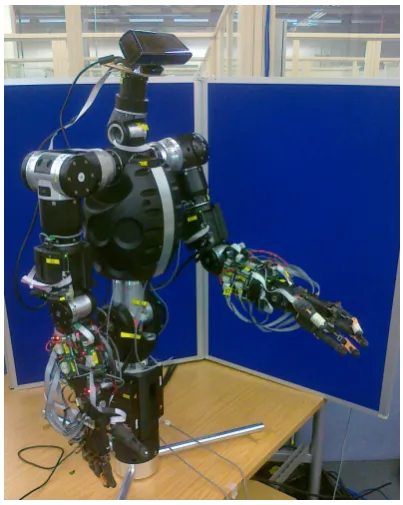
The majority of work presented in this thesis was done with a Bristol and Elumotion Robotic Torso (BERT) robot, shown in Figure 3.1. This is an upper torso humanoid robot, which is composed of harmonic drives and brushless DC motors. The motors are controlled with EPOS motor controllers and these in turn are driven by higher level software, running on a PC with communication over a Controller Area Network (CAN) bus. To give the robot a 3D vision system, a Microsoft Kinect has been used for the robots head. The Kinect is an affordable depth camera developed by the company Primesense, that uses an infra-red projector coupled with an infra-red camera as a stereo pair. The Kinect builds depth maps of the world with a resolution of 640x480 pixels at a frequency of 30Hz. The depth maps are fairly noisy, but a Kinect is very reliable and a lot easier to set-up than an equivalent stereo camera system.
estimate the forces being experienced by the robot’s arms.
Figure 3.1: The BERT robot examining its hand.
[image:36.595.225.427.470.691.2]3.2
Developed Control Software
A range of software systems were developed to support the experimental work carried out using the BERT and Baxter robots.
3.2.1
Software Developed for the BERT Robot
Figure 3.3 shows how the software systems that drive the BERT hardware are organised.
Figure 3.3: The hardware and software systems used to control BERT.
At the start of the project, the hardware shown in Figure 3.3 was already available. The software stack in Figure 3.3 was then built on top of it over the course of the first year. Adopting a bottom up approach, the first thing written was a library that controls the EPOS motor controllers by communicating over the CAN bus. The EPOS motor controllers are sophisticated pieces of hardware, which provide a range of options for controlling the motors attached to them. Options include position control, velocity control and current control. For now, the EPOS communication library exposes just the position control functionality of the motor controllers. The library provides the ability to set the desired position and speed of the actuators of the robot, as well as the ability to read back the current position of the actuators at a rate of 100Hz.
means to network together a number of individual software processes, in order to build robotic applications. The flexibility of being able to compose an application from a number of different processes, makes it very easy to distribute the processing over a number of machines. It also allows a number of other open source libraries to be used as services. For example, ROS provides wrapped versions of a number of planning libraries, which makes it very easy to incorporate inverse kinematics into the robotic system.
/kinect_base_link1
/rosout /kinect_base_link2
/kinect_base_link3 /kinect_base_link /root_broadcaster
/KinectToHandCalibrator
/RobotControlServer
/openni_node1
/MultiViewTracker
/rob_st_pub /rosout
/rosout
/rosout
/rosout
/rosout
/rosout
/rosout
/rosout
/rosout
/rosout /tf
/tf
/tf
/tf
/tf
/tf
/camera/rgb/points /processPositionCommandList /setMotorProfileVelocity /sendFaultReset
/joint_states
/tf /joint_states
[image:39.595.164.496.180.554.2]/actuator_states
Figure 3.4: This graph showing the nodes (processes) running for a hand tracking program, developed by the author, used for part of the work presented in Chapter 4. The directed edges between nodes represent communication channels, with /tf for example representing 3D transformation data, and /rosout representing status output from each of the nodes.
3.2.2
Software Developed for the Baxter Robot
low level work that had to be done to support the BERT robot, and to get it to move, was not necessary for the Baxter robot. In particular, Rethink Robotics provide a ROS interface for the Baxter robot that makes it easy to move the robot in position, velocity, or torque control modes. Therefore, the main work done to support the Baxter robot was to retarget some of the higher level programs to work with both it, and the BERT robot. This was straightforward, as the ROS interfaces the robots use for controlling motion are very similar.
3.2.3
Other Software Developed for the Robots
Alongside the software detailed in the previous sections, other software packages were developed for each of the other chapters in this work. This software made use of a number of open source 3rd party libraries such as Eigen (Guennebaud, Jacob, et al. 2010) for manipulating matrices and SciPy for numerical optimisation (Oliphant 2007). In general though, unless noted in a specific chapter, all software systems presented as part of this work were implemented by the author.
3.3
Evaluating Accuracy and Repeatability
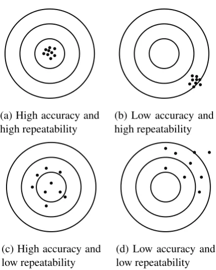
(a) High accuracy and high repeatability
(b) Low accuracy and high repeatability
(c) High accuracy and low repeatability
[image:41.595.219.433.140.408.2](d) Low accuracy and low repeatability
Figure 3.5: The possible combinations of accuracy and repeatability.
For industrial robots, the methods and procedures for measuring accuracy and repeatability are laid out in great detail in (ISO 9283 1998). To be done properly, these tests require a temperature controlled environment, and expensive equipment such as a 3D Coordinate Measuring Machine (CMM), and specially manufactured test load. For the work done in this thesis, it was only necessary to obtain a general indication of the accuracy and repeatability of the robots, and so it was decided that it was not worth the cost and effort required to perform the ISO 9283 (1998) tests in full. Instead some less complicated, easier to perform tests were devised and are described below.
3.3.1
Accuracy and Repeatability of the BERT Robot
position measurements. After each move the actual (x,y,z)position of the robot’s wrist joint relative to its base was measured with a tape measure, and compared to the commanded position. This showed that the BERT robot was accurate to within 3cm, in that all measured positions were within 3cm of the corresponding commanded positions.
The accuracy of a robot can be improved a lot with an accurate kinematic model, and so the relative inaccuracy of the BERT robot is not really something to be concerned about, especially considering that it was originally commissioned for recreating gestures for human robot interaction which do not generally require a high degree of accuracy. More important is the repeatability. Given a set of N
position measurements, with coordinates (x,y,z), the repeatability r of a robot is defined by ISO 9283 (1998) as follows.
r=l¯+3σ, (3.1)
where
¯
l= 1 N
N
∑
j=1lj, (3.2)
lj=
q
(xj−x¯)2+ (y
j−y¯)2+ (zj−z¯)2, (3.3) ¯
x= 1 N
N
∑
j=1xj,y¯= 1 N
N
∑
j=1yj,z¯= 1 N
N
∑
j=1zj, (3.4)
and
σ=
s
∑Nj=1(lj−l¯)2
N−1 . (3.5)
The repeatability of the BERT robot was measured by attaching a pen to the BERT robot’s left hand, and commanding it to a pose that made a mark on some graph paper, secured with tape in front of the robot. Making marks on paper meant that the repeatability was only measured in 2 dimensions (i.e. z=0 for all measurements), but this made measuring the repeatability easier and it was felt that repeatability in the z-axis was likely to be very similar to repeatability in the
3.3.2
Accuracy and Repeatability of the Baxter Robot
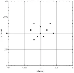
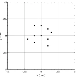
The tests carried out on the BERT robot were repeated for the Baxter robot, and the results obtained gave an accuracy of 1cm along with a repeatability of 3.02mm. The marks recorded for the repeatability test are shown in Figure 3.7
y
(m
m
)
−5
−2.5
0
2.5
5
x (mm)
[image:43.595.199.456.225.478.2]−5 −2.5 0 2.5 5
y
(m
m
)
−5
−2.5
0
2.5
5
x (mm)
[image:44.595.203.455.141.396.2]−5 −2.5 0 2.5 5
Figure 3.7: Marks made when measuring the repeatability of the Baxter robot.
3.3.3
Discussion
The repeatability values measured for the BERT and Baxter robots are not good compared with the repeatability quoted on datasheets for modern industrial robots. For example, the repeatability given for the ABB IRB 120 robot (a small industrial robot arm) is 0.01mm (ABB (2012)) which is 2 orders of magnitude better than the repeatability values measured for the BERT and Baxter robot.
Part of this discrepancy undoubtedly comes from deficiencies in the testing process that was used to measure the repeatability, which is much less rigorous than the ISO 928 method used to characterise the IRB 120 robot. However the main reason that the BERT and Baxter robots are less repeatable than the IRB 120 is that they have not been designed for high repeatability and are much less rigid than the IRB 120. The BERT robot has been constructed using 3D printed parts, and after a number of years there is fair amount of play in some of its joints. The Baxter robot is specifically designed to be compliant so that it is safe to work alongside, and in close proximity to humans (unlike the IRB 120 which must be installed in a safety cage). Indeed, the data sheet for the Baxter robot (RethinkRobotics (2015)) makes no mention of repeatability instead emphasising the safety of the compliant arms.
the robot to learn about itself, and manipulating hand held objects in ways which do not require very precise and repeatable motion.
3.4
Controlling the Movement of the Robots
The focus of this work is on building systems that allow robots to autonomously build models of themselves, and objects in the world around them using active computer vision and exploratory actions. Overall, the models built focus on characteristics such as appearance, or physical dimensions. The dynamic characteristics of the robot and examined objects, i.e. how they respond to forces and torques are largely ignored and considered beyond the scope of this thesis. This is because it was felt that incorporating dynamic effects into the model building process would over-complicate things.
Chapter 4
Autonomously Building Models of
the Robot’s Arm
This work focuses on building robots and robotic systems which can autonomously construct models of themselves and the external objects with which they interact. In particular, active 3D vision is used as a tool that a robot can use to explore itself, and its surroundings, in order to autonomously construct models.
The increasing availability of reasonably priced depth cameras such as the Mesa Imaging SwissRanger, or the Microsoft Kinect has made it easier for robotic systems to perceive the world in 3D. These cameras provide depth values for pixels in the image, and so produce a 3D point cloud in camera space. The quality of the point clouds produced by these cameras reduces the need for researchers to setup technically challenging stereo camera systems, which often rely on the presence of highly textured areas in order to achieve reasonably similar results.
A practical problem for a robot with 3D vision, is the task of relating the movements of its body to the Cartesian space of its camera system, so that it can interact with objects it sees. More fundamental than that, it may also be a problem for the robot to work out which parts of a 3D image belong to its body and to its hand.
This chapter presents a solution to both of these problems in the form of a system that allows a robot to reliably identify its hand in its field of view, and then to build a kinematic model of its arm in camera space. Building the kinematic model in camera space implicitly determines the transformation between camera space and the model. Once the kinematic model is built, inverse kinematics can be used to accurately move the manipulator of the robot in camera space. In effect, the robot is therefore able to ‘bootstrap’ itself, from a state of fairly limited knowledge, to having a kinematic model of its arm, which it can then use to further interact with, and to explore, the world.
identify the location, and extents of the robot’s hand in its field of view. It then uses a simple form of visual servoing to move the hand to the centre of the field of view, in order to maximise the quality of the subsequent processes. Once centred, the system builds a model of the robot’s hand by turning the hand in front of a Kinect depth camera, whilst aligning and merging the point clouds obtained from the Kinect into a common reference frame. The model is then used to track future movements of the hand, by aligning the model against incoming point clouds. This system has the useful property of not just providing an estimate for the transformation of the hand in camera space, but also providing a 3D model of the hand which can be useful for other tasks such as planning grasps, or checking for collisions between the robot and the environment.
Once a model of the robot’s hand has been built and is being tracked, it is then used to automatically build a kinematic model of the robot’s arm by tracking the movement of the hand as each revolute joint in the arm is rotated in turn. This allows the robotic system to build an accurate model of its arm, starting with very little information. This is an advantage, as a robot that can deduce information for itself, is potentially more robust, and requires less work to commission.
The rest of the chapter proceeds as follows. Section 4.1 describes related work and reviews the techniques which were used to build the system. Section 4.2 provides a description of how the robotic hand is modelled and tracked along with details of automatically building a kinematic skeleton for the robotic system. Section 4.3 evaluates the accuracy of the system, and Section 4.4 presents conclusions along with ideas for future work.
4.1
Background and Related Work
4.1.1
Exploratory Motion and Active Vision
The work of Ballard (1991) was amongst the first to look in depth at camera systems which were not simply passive. Ballard observed that more information may be obtained from a visual scene, or obtained at a lower computational cost, through the process of moving the camera system and observing the scene from a number of different viewpoints. Such systems are often termed active vision systems to distinguish them from passive vision systems.
motion could be reliably detected, even in the presence of a large amount of distracting motion. Work has also been done by Katz and Brock (2008) on using exploratory motions to autonomously identify the structure of articulated objects.
4.1.2
Object Modelling and Tracking
When building models from range data, such as that obtained from a laser scanner or depth camera, the Iterative Closest Point (ICP) algorithm presented by Y. Chen and Medioni (1991) and Besl and McKay (1992) is a widely used algorithm for aligning one depth camera frame with either another frame, or with a reference model.
The ICP algorithm has been the subject of much research since its initial presentation. Rusinkiewicz and Levoy (2001) identified the key stages that make up the ICP algorithm, outlining a number of techniques for making the algorithm more efficient and speeding up convergence. The ICP algorithm was used as a key part of an object modelling and tracking system built by Weise et al. (2009), and a very similar system was used to build models of objects held in a robot’s hand by Krainin et al. (2011). In both of these systems, models were constructed by first aligning point clouds from a depth camera into a common coordinate frame, using the ICP algorithm. Subsequently, corresponding points from the point clouds were averaged together to form surfel (surface element) models. Surfels as described in (Pfister et al. 2000) are orientated 3D points, which can be used to describe complex geometric objects without explicit connectivity information. The advantage of averaging point clouds together to form a surfel model is that it smooths out a lot of noise that would otherwise accumulate as a result of estimating lots of small transformations (Henry et al. 2010).
Tracking a robot’s hand in camera space is a special case of tracking an arbitrary 3D object in camera space, and this is an active area of research with Lepetit and Fua (2005) providing a comprehensive survey of the main techniques. Fiducial tracking (Sturm, Plagemann, et al. 2009) involves tracking markers attached to the object of interest. Model based tracking involves posing a 3D model of the object of interest to best match the information coming from the camera. This method has been used extensively in human hand tracking applications, such as (Sudderth et al. 2004).
4.1.3
Kinematic Identification
for a revolute joint. Another method for identifying the joint axes of a robot is the Jacobian Matrix Method of Bennett et al. (1992), this method requires either joint torque sensors or a method of estimating the linear and angular velocity of the robot’s end link.
More recently, the field of developmental robotics has taken an interest in kinematic identification. Here, it has been explored as part of more general efforts to enable robots to build and maintain a body schema for themselves. In the context of robotics, Hoffmann et al. (2010) describe a body schema as a group of body representations, which allow an embodied agent to control its actions, and to integrate sensory information such as vision or touch into common frames of reference. These representations may include kinematic and dynamic models, and the emphasis is on building the models autonomously. The aim is to give a robot the ability to adapt to changes in its body due to damage, or to dynamically extend its body schema to allow the use of tools. Hersch et al. (2008) built a kinematic model of a robot by observing end effectors using an iterative gradient descent approach. Sturm, Plagemann, et al. (2009) presented a system that uses a Bayesian network to learn arbitrary kinematic chains, which can also cope with changes in the kinematic chains as the system runs. This system however, requires observations of all joint positions to build the kinematic chain, whereas the system presented here only needs to observe the movement of the end of the chain.
Finally, recent work by Hart and Scassellati (2011) takes a similar approach to the one presented here. The difference lies in the fact that the method of Hart and Scassellati requires an Augmented Reality (AR) marker to track the hand, whereas the method presented here builds and tracks a complete model of the robot’s hand, and so can operate without AR markers.
4.2
Method
As this work is largely concerned with the development of self-learning robots, an attempt is made to reduce the amount of a priori information available, while making certain assumptions to ensure that the task remains tractable. It is assumed that an attainable starting pose for the robot is given, such that the robot’s hand is visible to the robot’s vision system. It is also assumed that the range of motion, and gearing ratio (used to convert from encoder ticks, to angles), of all of the robot’s actuators are known. Finally, it is assumed that the relative order of the robot’s actuators is available, i.e., that it is known that the elbow actuators come after the shoulder actuators etc. Everything else the robot needs to know, it deduces in a series of steps.
BERT robot can damage itself if it attempts to move beyond its range of motion. It would be interesting however to consider how this initial set of assumptions could be reduced still further, but discussion of how th