II
II
II
II
II
II
|
II
il
II
II
II
II
II
II
II
II
|
I!
|
I m p l e m e n t i n g a Sense Tagger in
a General A r c h i t e c t u r e for Text Engineering
H a m i s h C u n n i n g h a m , M a r k S t e v e n s o n a n d Y o r i c k W i l k s D e p a r t m e n t o f C o m p u t e r Science,
U n i v e r s i t y o f Sheffield,
R e g e n t C o u r t , 211 P o r t o b e l l o S t r e e t , Sheffield S1 4 D P , U K
{hamish, marks, yorick}@dcs.shef.ac.uk
http://www, des. shef. ac.
uk/research/groups/nlp/gate/
Abstract
We describe t w o systems: GATE (General Ar-
chitecture for Text Engineering), an architec- ture to aid in the production and delivery of language engineering systems which signifi- cantly reduces development time and ease of reuse in such systems. We also describe a sense tagger which we implemented within the GATE architecture, and which achieves high accuracy (92% of all words in text to a broad semantic level). We used the implementation of the sense tagger as a real-world task on which to evaluate the usefulness of the GATE architecture and identified strengths and weak- nesses in the architecture.
1 I n t r o d u c t i o n
This paper is about two things: a novel hybrid sense tagger for unrestricted text (Wilks and Stevenson, 1997), and the experience of developing this sys- tem within GATE - a General Architecture for Text Engineering (Cunninham et al., 1997; Cunningham, Wilks, and Gaizauskas, 1996a).
We hope you can forgive this mild schizophrenia
- we feel that both topics are relevant to the sub-
ject of new methods in NLP: the first because both the problem of arriving at methods for sense tag- ging and of tuning those methods to specific domains and lexical resources is an increasingly active topic in the field (Basili, Della Rocca, and Pazienza, 1997; Harley and Gleanon, 1997); the second because work on NLP components shares a heap of problems with other language processing work to do with reusabil- ity, data visualisation, and software-level robustness and efficiency that, we feel, are best solved by the provision of a inclusive and general architecture and development environment for the field.
We begin with a review of the general concept behind GATE (section 2), then describe the practi- calities of the system that are relevant to the sense tagging system we have developed (section 3). Next
we discuss the sense tagging problem (section 4), and then our system (section 5). Finally we look at the experience of developing the tagger within the architecture (section 6), and draw out some lessons for the future (section 7).
2 G A T E -
t h e concept
GATE is an architecture and development environ- ment for research and development workers in NLP and Language Engineering 1. It is an architecture in the sense that it specifies a macro-level organisa- tionai pattern for the various components and data resources that make up a language processing (ac- tually at present only text processing) system (Shaw and Garlan, 1996). It is also a development envi- ronment that adds a rich set of graphical tools to the architecture enabling the developer to easily in- tegrate new processing componemts, to manage flow of control between components, to visualise the data produced by and passed between components, and evaluate the contribution of components to some ex- ternally defined and measured language processing task.
As w e ' v e noted elsewhere (Cunningham ,
Gaizauskas, and Wilks, 1995; Cunningham,
Wilks, and Gaizauskas, 1996b), the motivating factors behind development of the architecture included the facilitation of reuse of components (which has previously been successful in NLP only
tThe application of NLP and CL theory to the cre- ation of practical applications software has recently be- come known as Language Engineering, or LE, or NLE, and has been defined in various ways in e.g. (Mitkov, 1996; Thompson, 1985; Boguraev, Garigiiano, and Tait, 1995; Gazdar, 1996). Our gloss on these various defin- itions is that Language Engineering is the discipline or act of engineering software systems that perform tasks involving processing human language. Both the con- struction process and its outputs are measurable and predictable. The literature of the field relates to both application of relevant scientific results and to a body of practise.
Cunningham, Stevenson and Wilks 59 Implementing a Sense Tagger
Hamish Cunningham, Mark Stevenson and Yorick WilEs (1998) Implementing a Sense Tagger in a General Architecture for
for data resources (Curmingham,, Freeman, and Black, 1994; Cunningham, 1994)), comparative and task-based evaluation, collaborative research, and software-level robustness, efficiency and portability. The design we arrived at in support of these aims is sketched in the rest of this section.
NLP systems produce information about texts (which may sometimes be the results of automatic speech recognition) and existing systems that aim to provide software infrastructure for NLP can be clas- sifted as belonging to one of three types according to the way in which they treat this information:
a d d i t i v e , o r m a r k u p - b a s e d : information pro- duced is added to the text in the form of markup, e.g. in SGML (Thompson and McKelvie, 1996);
r e f e r e n t i a l , o r a n n o t a t i o n - b a s e d : information is stored separately with references back to the original text, e.g. in the T I P S T E R architecture (Grishman, 1996);
a b s t r a c t i o n - b a s e d : the original text is preserved in processing only as parts of an integrated data structure that represents information about the text in a uniform theoretically-motivated model, e.g. attribute-value structures in the ALEP system (Simkins, 1994).
A fourth category might be added to cater for those systems that provide communication and control infrastructure without addressing the text-specific needs of NLP (e.g. Verbmobil's ICE architecture (Amtrup, 1995)).
As noted at a previous conference in this series (Cunningham, Wilks, and Gaizauskas, 1996b), we believe that performance and other considerations favour the referential approach, but also that SGML is a key part of any general text processing strategy. The first design decision we made, then, was to base GATE on a referential core using the T I P S T E R ar- chitecture, and to cater for SGML via I / O format conversion filters. This led to the development of one of three key pillars of the system: GDM, the GATE Document Manager. GDM and the TIP- STER API that it implements forms a buffer be- tween processing modules in a GATE-based NLP system. Modules no longer talk to each other, with the coherence and coupling implications that direct unrestricted communication can imply, but to GDM via the T I P S T E R API.
One of the key benefits of adopting an explicit ar- chitecture for data management is that it becomes possible to easily add a of layer graphical interface access to architecural services and data visualisation
tools, and such a layer is our second pillar: GGI, the GATE graphical interface. GGI has functions for creating, viewing and editing the collections of doc- uments which are managed by the GDM and that form the corpora which LE modules and systems in GATE use as input data. It also has facilities to display the results of module or system execution - new or changed annotations associated with the doc- ument. These annotations can be viewed either in raw form, using a generic annotation viewer, or in an annotation-specific way, if special annotation view- ers are available. For example, named entity annota- tions which identify and classify proper names (e.g. organization names, person names, location names) are shown by colour-coded highlighting of relevant words; phrase structure annotations are shown by graphical presentation of parse trees. Note that the viewers are general for particular types of annota- tion, so, for example, the same procedure is used for any POS tag set, Named-Entity markup etc. Thus developers reuse GATE data visualisation code with negligible overhead.
Lastly, the third pillar of the system is the one that does all the real work of processing texts and discov- ering information about their content: CREOLE, a Collection of REusable Objects for Language Engi= neering. In a sense CREOLE isn't part of GATE at all, but is the set of resources currently integrated with the system, but we also use the term to refer to the mechanismss available for integrating modules into GATE. This process has been automated to a large degree and can be driven from the interface. The developer is required to produce some C + + or Tcl code that uses the GDM TIPSTER API to get information from the database and write back re- sults. When the module pre-dates integration, this
is called a wrapper as it encapsulates the module in
a standard form that GATE expects. When mod- ules are developed specifically for GATE they can embed T I P S T E R calls throughout their code and dispense with the wrapper intermediary. The under- lying module can be an external executable written in any language (the current CREOLE set includes Prolog, Lisp and Perl programs, for example).
CREOLE wrappers encapsulate information about the preconditions for a module to run (data that must be present in the GDM database) and post-conditions (data that will result). This information is needed by GGI, and is provided by the developer in a configuration file, which also details what sort of viewer to use for the module's results and any parameters that need passing to the module. These parameters can be changed from the interface at run-time, e.g. to tell
Cunningham, Stevenson and Wilks 60 Implementing a Sense Tagger
II
II
II
II
II
II
II
II
II
II
II
II
II
II
II
II
a parser to use a different lexicon. Aside from the information needed for G G I to provide access to a module, GATE compatibility equals T I P S T E R compatibility - i.e. there will be very little overhead in making any T I P S T E R module run in GATE. Given an integrated module, all other interface
functions happen automatically. For example,
the module will appear in a graph of all modules available, with permissible links to other modules automatically displayed, having been derived from the module pre- and post-conditions. At any point the developer can create a new graph from a subset of available CREOLE modules to perform a task of specific interest.
The integration mechanisms also reduce the doc- umentation load: users can reference the T I P S T E R A P I to describe the interchange format of the data they produce and the G A T E documentation for in- tegration details. Of course GATE doesn't solve all the problems involved in plugging diverse LE mod- ules together. There are three barriers to such inte- gration:
• managing storage and exchange of information
about texts;
• incompatibility of representation of information
about texts;
• incompatibility of type of information used and
produced by different modules.
GATE provides a solution to the first two of these, allowing the integrator to concentrate on the core issue of the meaningful content of the information exchanged.
3 G A T E - p r a c t i c a l i t i e s
A main purpose of G G I is to allow execution of the modules within GATE and to provide a graphical access point to the results they produce. Section 3.1 describes the meaning of the primitives in the graph and how it is executed, section 3.2 describes the method used to autogenerate the graph, sec- tion 3.3 discusses the method of creating manageable subgraphs, and section 3.4 discusses results visuali- sation facilities.
3.1 G r a p h S y n t a x a n d S e m a n t i c s
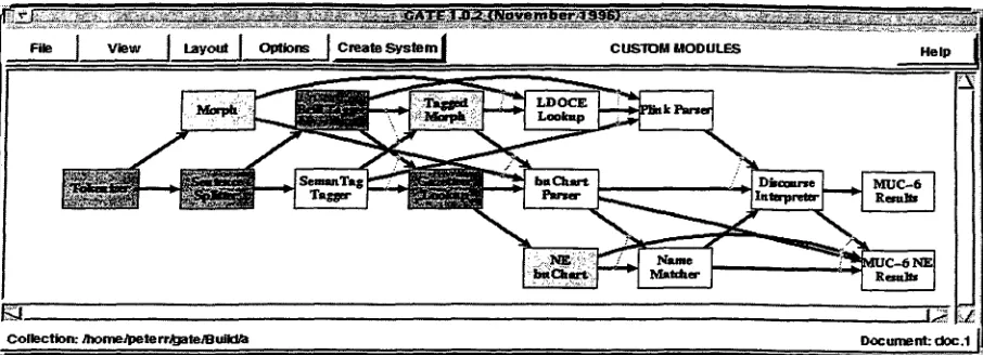
An example of a system graph is shown in figure 12. A system graph is an executable graph, and is
~These and other screen dumps below look better in colour! The description below will be a bit like the TV snooker commentator who said "For those of you watch- ing in black and white, the pink is behind the blue".
a simple data flow program. Modules are shown as nodes in the graph, with the data flow indicated by the arcs. Each incoming arc to a module indicates a dependency on results of previous processing. All modules at the source of arcs connecting to a de- pendent module must be run before the dependent module is executed, except where the incoming arcs are connected by lines, in which case the module re- quires the execution of only one of the modules at the other end of the arc (these arcs are then termed or-arcs). Thus, in the example graph of figure 1,
the buChart Parser module may only be run if the
results of the G a z e t t e e r Lookup module and either the Tagged Morph module or the Morph module are available. They in turn have earlier dependencies. The T o k e n i z e r module has no dependencies and so begins execution. There are two modules with no downstream children: MUG-6 R e s u l t s and MUG-6 NE R e s u l t s , so either of these must produce an end result. However, because results from modules in the middle of the graph may be of interest to a NLP researcher, any module can be chosen as the final one that will be executed. ,e ~..
At any point in time, the state of execution of the system, or, more accurately, the availability of d a t a from various modules, is depicted through colour- coding of the module boxes. Figure 1 shows a sys- tem window. Light grey modules (green, in the real display) can be executed. Modules that require in- put from others not yet executed, and so cannot be executed yet, are shown with a white background (amber, in reality). The modules that have already been executed are shown in dark grey (red), at which point their results are available from a menu associ- ated with each box (see below).
The system graph can either be run in batch mode or in an interactive manner. To run in batch mode, the user selects a path though the graph and clicks on the final module. The current state of the graph, and the document (or collection of documents) cur- rently undergoing execution is shown. The system ensures that the path chosen by the user is valid by only allowing a module to be selected if all its inputs have already been selected. Selected modules are ex- ecuted in a d a t a driven manner, with modules being executed as soon as their input data is available.
The interactive mode is designed for module de- velopers. The modules under development can be executed as with the batch mode then the module or modules to be retried (after the underlying code or resources have been changed) can be reset by a mouse click. This clears the database of the post- condition annotations and allows the modules to be rerun.
Collection: Jhome/IPete rr/gatelB m'kl~
Figure 1: The G A T E System Graph
The nature of-the database (where each module produces a specific set of annotation types) means that it is possible to view partial results of execu- tion without recourse to buffering intermediate data
(Woodruff and Stonebreaker, 1995).
3.2 A u t o g e n e r a t i o n
The graph shown in figure 1 is in fact the custom
graph. This is the system graph that shows all the modules in the particular GATE environment. The custom window is automatically generated from the configuration information that is associated with each module, e.g., for the buChart module:
seZ creole_config(buchart) {
title {buChart Parser} pre_condi~ions {
document_attributes {language_english}
annotations {token sentence morph lookup} }
post_conditions {
document_attributes {language_english} annotations {name syntax semantics}
}
viewers {
{name single_span} {syntax t r e e } {semantics raw}
} }
This d a t a structure (actually a Tcl array (Ouster- hout, 1994)) describes the T I P S T E R objects that a module requires to run, the objects it produces, and the types of viewers to use for visualising its re- sults. Along with code that uses the T I P S T E R API to get information from the database and to store results back there, this configuration file is all that an integrator need produce to connect a module to GATE. Typically the biggest overhead here is con- verting pre-existing modules to preseve byte-offset information. See (Cunningham et al., 1996) for de- tails.
The autogeneration algorithm creates data flow arcs from modules that have an annotation type in their postconditions to the other modules that have the same annotation type in their precondition. For example, G a z e t t e e r Lookup has the annotation type lookup in its postconditions, so an arc connects it with buChart P a r s e r , which has that annotation type in its preconditions. Arcs are not created be- tween modules that operate on different languages, however in figure 1, all the modules operate on Eng- lish language documents. When more than one mod- ule has the same annotation type in its postcondition then it is assumed that either module may produce
the required result, and so the two arcs are or-arcs
and are connected by a line (both l~orph and Tagged
Horph produce the same annotation and so have or-
arcs into buChart
Parser).
The most computationally expensive part of auto- generation goes into discarding redundant arcs. Re- dundant arcs are those that connect an upstream module to a downstream module where it can be deduced that the preconditions of modules between the two given modules cover the annotation types that the arc represents. For example, the T o k e n i z e r produces annotation types required by b u C h a r t P a r s e r , but there is no need for a data flow arc be- tween these modules as modules between them also require these annotation types.
The autogeneration facility allows easy integration of new modules into GGI. Most NLP tasks can be expressed in the simple data flow techniques of this system, but it is currently not possible to integrate NLP tasks that require iteration.
Some modules have the same annotation t y p e in both pre- and postconditions. These modify the re- sult of previous computation and pass the d a t a flow
Cunningham, Stevenson and Wilks 62 Implementing a Sense Tagger
II
II
II
II
II
II
II
II
II
II
II
II
II
II
II
II
II
[image:4.612.83.536.63.227.2]|
m
N
II
B
m
B
B
B
g
|
B
I
|
down stream. This kind of module, termed a filter,
cannot be automatically positioned in the diagram, instead the user selects the position of filters from the arcs on which they m a y appear (arcs from mod- ules that produce the annotation type the filter op- erates on). During execution filters are treated as normal modules.
3.3 C u s t o m i s i n g G r a p h s
The system graphs are displayed with a graph draw- ing tool which is is also used in tree based visuali- sation tools available for display of e.g. syntactic parse results. This tool allows commands to be as- sociated with nodes, hence it can be used for data flow graphs. It has a layout algorithm based on the method used by daVinci (FrShlich and Werner, 1995) to minimise arc crossing.
G G I suffers from the scaling problem (Burnett et al., 1987), as the size of the custom graph quickly becomes unmanageable. This can be alleviated by creating new system graphs from specified subgraphs of the custom graph. A later release will allow col- lapsing of graph sections.
It is possible to group these derived system graphs together so t h a t the user m a y chose from a selection of tasks at the top level of G G I (not shown here for space reasons). Having chosen a task (e.g. parsing), an intermediate level display appears, presenting the user with a selection of icons, one for each of the one or more specific systems capable of performing the selected task (e.g. the buChart parser or the Plink parser). Once a particular system is selected, a final window appears displaying the appropriate system graph.
3.4 Visuallsing Results
NLP data is wide ranging in scope but has specific characteristics that mean the problems with visual- ising large amounts of d a t a (Burnett et al., 1987) are less significant. This is because either the infor- mation can be visualised as coloured markup on the text (meaning that the text can be displayed using traditional textual techniques (Jonassen, 1982)), or the information is grouped over small segments of text, such as paragraphs or sentences.
G G I has several viewers for the display of TIP- S T E R annotations. The viewer for each postcondi- tion annotation is specified by the module config- uration file, an example of which i o given in sec- tion 3.2. The viewers can be classified into those which display the text and overlay the annota- tions as colours or shades ('single span', 'multiple span', 'text-attribute'); and those that visualise a more complex relationship between annotations in
= • - w ~ ~ to the a ~ l y ~ e ~ s l ~ i t £ o a of vicul ~ c~ k y la~ Cotla:;, a ~ i v ~ e ~ y held
wa~ l ~ e V i c L ~ l y ~c,~lde~. a~l ¢:~.~ q ~ a t . i ~ g o f f i ~
~ese p ~ e i t l e n s ~ ' t b e filled, l a - ~ d , L a r r y ~. Harl~.
~eviauely e ~ i v e v i ~ ~ I d ~ of ~:$; ¢ ~ i ~ |~¢ the
~ i ~ uuit, was n ~ tO the ~ l y ~ e a t e d ~ of ~ e ~ i d ~ of
~:S: opezatiaa~. ~ d alaug with the head ~ Interaatloaal
o ~ a ~ i ~ , ~ill r e 1 ~ gl~re~ly to Oal~ P. P ~ , t ~ ~ L V O
a f f ~ of t ~ l~a:mt ~m~m~,
~efle~s the ~ugreu£ e ~ i s ~t Mazy ~ay an i~e~a~ti~a2
. ' ~ a ~ i ~ . ~ ~ i l l be i n v o l v '~1 £n d~/elopla~ the ~ e r a ~ : i ~ t ¢aqam~la~ ~ z ~ y , ~ aald.
5
D~mtss I
Figure 2: Multiple Span Viewer
an acyclic graph format ('tree'). Where no viewer is specified, a default annotation dump is displayed. The configuration file for the buChart P a r s e r mod- ule in section 3.2 specifies that the 'name' annotation type is assigned the 'single span' viewer, 'syntax' the 'tree' viewer, and 'semantics' the 'raw' or annotation dump viewer. New viewers can be written where the default ones are not appropriate for new annotation types.
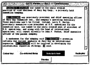
The 'single span' and 'text-attribute' viewers are fairly simple, assigning different colours to each an- notation. 'multiple span' is more complex, as it is designed to view annotation chains. An annotation chain is a list of annotations specified by annotation references. The user chooses a highlighted p a r t of the text, and all the other highlights that are part of the same chain are displayed. Figure 2 shows this viewer displaying the results of a coreference task. Coreference identifies elements of the text t h a t are interpreted as referring to the same real world en- tity. For example, a person and a pronoun might be coreferential. In figure 2 the user has chosen one of the highlights referring to 'Richard Bartlett'.
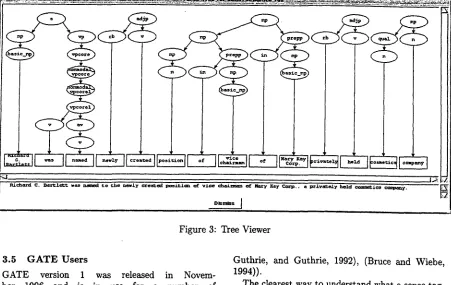
The 'tree' viewer containing 'syntax' annotations (produced by the buChart P a r s e r ) is shown in fig- ure 3. The parse trees currently integrated into GATE span at most a sentence, so that the tree size is always manageable.
The viewers are activated by first clicking with the mouse on a module whose results are present (i.e. it has been executed and it's box has turned red) which reveals a menu of annotations; choosing an annotation brings up the appropriate viewer.
There is a certain amount of connectivity between these viewers, as it is possible to click on a node in the parse tree and have the area of text highlighted in a text display window, or it is possible to highlight areas of text and display the raw annotations that are contained within the highlighted span.
[image:5.612.327.515.58.194.2]_ _ ~ f E
I
)
! aca:ll
b ) ( v
J - . _ D
! ,.
: I
i
Richard C. Bartl~&t was n ~ 4 t o ~ho n ~ l y C~ga~. ' ' 4 poolt~on of v £ ~ ~haizz~aa of Rklr~ Kay ~ . , a priva~oly hold , ~ - ~
D ~ mdss ]
Figure 3: Tree Viewer
3.5 G A T E U s e r s
GATE version 1 was released in Novem-
ber 1996 and is in use for a number of
projects around the World - see for ex-
ample hztp: llw~a, sics. se/humle/proj ects/
s v e ns k/ s v e ns k, html, who evaluated
the system relative to ALEP, and
ht~p://wvv, des. shef. ac. uk/research/gr0ups/
nlp/gate/users.html. Figure 4 lists the sites t h a t have licenced the system so far.
4 W o r d s e n s e t a g g i n g
We have recently implemented a sense tagger within the GATE framework.
Sense tagging is the process of assigning the ap- propriate sense from some semantic lexicon to each word 3 in a text. This is similar to the more widely known technology of part-of-speech tagging, but the tags which are assigned in sense tagging are semantic tags from a dictionary rather than the grammatical tags assigned by a part-of-speech tagger.
Our sense tagger uses the machine readable ver-
sion of Longman Dictionary of Contemporary Eng-
lish (LDOCE) (Procter, 1978) to provide the se- mantic tag set. LDOCE is a learners' dictionary - one designed not for native speakers of English but for those learning English as a second language and has been used extensively in machine readable dic- tionary research ((Ide and Veronis, 1994), (Cowie,
3This is often loosened to each content word.
Guthrie, and Guthrie, 1992), (Bruce and Wiebe, 1994)).
The clearest way to understand what a sense tag- ger does is to look at an example of the output we
would like it to produce. Consider the sentence "The
interest on my bank account accrued over the years",
our tagger should assign a single sense from LDOCE to each of the content words in the sentence. The choice of senses in the assignment should be the same as that a human would choose. An example of a de- sired assignment is shown in figure 5.
As can be seen from the senses assigned, each LDOCE sense has a homograph and sense number, these are used to identify different levels of seman- tic distinction between senses and act as identifying markers. Homograph distinctions signify broad se- mantic differences between senses (such as the 'edge
of river' and 'financial institution' senses of bank)
while sense distinctions signify differences between senses which are more related (such as the 'building' and 'company' senses of the word). These numbers are followed by the textual definition of the sense and, possibly, by an example sentence which is a par- ticular use of the sense and is printed in this type 4.
The information provided by these tags is poten- tially valuable for downstream tasks in a language processing system. For example, the system could
benefit from knowing that "bank" in this case means
4LDOCE senses have additional information such as subject categories, subcategorisation information and se- lectional restrictions which we do not show here.
Cunningham, Stevenson and Wilks 64 Implementing a Sense Tagger
m
m
m
m
m
m
m
m
m
m
m
m
m
m
m
m
[image:6.612.82.533.69.354.2]senses in texts. A natural extension to this obser- vation is to create a disambiguation system which makes use of several of these independent knowledge sources and combines their results in an intelligent way.
Our system is based on a set of partial taggers,
each of which uses a different knowledge source, with their results being combined. Our system is in the tradition of McRoy (McRoy, 1992), who also made use of several knowledge sources for word sense dis- ambiguation, although the information sources she used were not independent, making it difficult to evaluate the contribution of each component. Our system makes use of strictly independent knowledge sources and is implemented within GATE whose plug-and-play architecture makes the evaluation of individual components more straightforward.
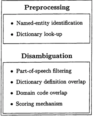
At the moment the sense tagger consists of six stages (shown in figure 6), the first two preprocess the text which is to be disambiguated while the re- maining four carry out the disambiguation.
P r e p r o c e s s i n g
• Named-entity identification
• Dictionary look-up
Disarnbiguation
• Part-of-speech filtering
• Dictionary definition overlap
• Domain code overlap
* Scoring mechanism
Figure 6: Stages in the Sense Tagging process
1. The text is first processed by a named-
entity identifier, which we developed as
part of Sheffield's entry for MUC-6 (Wakao, Gaizauskas, and Humphries, 1996; Gaizauskas et al., 1996). This identifies certain forms of proper names in the text and classifies them as either place, person, organization or location. For details of the classification scheme see (Def, 1995). We make no use of these classifications at present, however, they are of potential use to a module carrying out disambignation using
selectional restrictions.
The tagger does not attempt to disambignate any words which are identified as part of a named-entity.
2. The remaining text is stemmed, leaving only morphological roots, and split into sentences. Then words belonging to a list of stop words s are removed. The words which have not been identified as part of a named entity or removed because it is a stop word are considered by the
system to be ambiguous words and those are the
words which are disambignated.
For each of the ambiguous words, its set of possible senses is extracted from LDOCE and stored. Each sense in LDOCE contains a short textual definition (such as those shown in figure 5) which, when extracted from the dictionary, is processed to remove stop words and stem the remaining words.
. The text is tagged using the Brill tagger (Brill, 1992) and a translation is carried out using a manually defined mapping from the syntactic tags assigned by Brill (Penn Tree Bank tags (Marcus, Santorini, and Marcinkiewicz, 1993)) onto the simpler part-of-speech categories asso- ciated with LDOCE senses 6. We then remove from consideration any of the senses whose part- of-speech is not consistent with the one assigned by the tagger, if none of the senses are consis- tent with the part-of-speech we assume the tag- ger has made an error and leave the set of senses for that word unaltered.
4. Our next module is based on a proposal by Lesk (Lesk, 1986) that words in a sentence could be disambiguated by choosing the the sense which produced the maximum overlap of the content words in the textual definitions of the word's senses. In practise this led to massive compu- tations with as many as 10 l° possible combina- tions of senses for a single sentence.
Cowie et. al. (Cowie, Guthrie, and Guthrie, 1992) used simulated annealing (Kirkpatrick, Gelatt, and Vecci, 1983), a numerical optimisa- tion algorithm, to make this process tractable.
5In our system a stop word is defined to be any word which is not a noun, verb, adjective or adverb. Preposi- tions are included in the list of stop words and are not disambiguated.
6The BriU tagger uses the tag set from the Penn Tree Bank which contains 48 tags (Marcus, Santorini, and Marcinkiewicz, 1993), LDOCE uses a set of 17, more general, tags.
Cunningham, Stevenson and Wilks 66 Implementing a Sense Tagger
II
II
II
II
II
II
II
II
II
II
II
Ii
II
[image:8.612.111.276.314.516.2]m
m
|
I
m
m
R
I
m
m
m
The simulated annealing algorithm proceeds by disambiguating a sentence at a time. A ran- dom configuration of senses is chosen such that one Sense is assigned to each ambiguous word in the sentence. A score is given to this config- uration based on the number of content words which are shared between the textual definition in the senses. Other, random, configurations are then generated and the simulated annealing algorithm is used to optimise over them. When this process is complete the algorithm returns a configuration which assigns the optimal config- uration of senses based on the overlap of words in the definition text.
This process identifies a single condidate LDOCE sense for each ambiguous word.
5. The text is then run through a module which optimises the overlap of domain codes for the senses of nouns in each paragraph of the text. The optimisation algorithm used is similar to simulated annealing (see section 4), although it has been modified in two ways. Firstly, we maximise the overlap of the pragmatic codes as- sociated with the word senses rather than the content words in their definitions. Secondly, we optimise over entire paragraphs at a time rather than just sentences, this is done because there is good evidence (Gale, Church, and Yarowsky, 1992) that a wide context, of around 100 words, is optimal when disambiguating using domain codes. This process, like the previous module, identifies a single candidate sense for each am- biguous word.
6. The final stage is to combine the results of the preceding processes. This is done using a very simple mechanism which we plan to re- place with an optimisation algorithm. We as- sign a score to each of the senses of the am- biguous words. These scores are initialised to 0 and +1 is added to a sense's score for each of the simulated annealing or pragmatic code modules which select that sense. The sense with the highest score is chosen as the tag for each ambiguous word. If there is a tie (two senses with the same score, which will happen if the two partial taggers disagree) it is broken by choosing the first sense, as listed in the dictio- nary. This is a sensible tie-breaker since the senses are roughly ordered by frequency of oc- currence in text 7. After this process is com-
7We are using the 1st Edition of LDOCE in which the publishers make no claim that the senses are ordered by
pleted every ambiguous word has exactly one sense from LDOCE associated with it, this sense is the tag which our system has assigned to that word.
We have conducted some preliminary testing of our tagger: our tests were run on 14 hand- disambiguated (by one of the authors) sentences from the Wall Street Journal, amounting to a 250 word corpus. We found that, of the tokens with more than 1 homograph in LDOCE, 92% were as- signed the correct homograph and 75% the correct sense using our tagger. These figures should be com- pared to the 72% correct homograph assignment and 47% correct sense assignment reported by Cowie et. al. (Cowie, Guthrie, and Guthrie, 1992) using sim- mulated annealing alone on the same test set.
6 D e v e l o p i n g t h e t a g g e r w i t h G A T E
The sense tagger was implemented as a set of 11 CREOLE modules, 6 of which had been imple- mented as part of VIE and the remaining 5 were de- veloped specifically for the sense tagger. These were implemented in a variety of programming languages: C[++], Perl and Prolog. These five modules are var- ied in their implementation methods. Two are writ- ten entirely in C + + and are linked with the GATE executable at runtime using GATE's dynamic load- ing facility (see (Cunningham et al., 1996)). Three are made up of a variety of Perl scripts, Prolog saved states or C executables, which are run as external processes via GATE's Tcl (Ousterhout, 1994.) API. This is typical of systems we have seen built using GATE, and illustrates its flexibility with respect to implementation options.
The GATE graphical representation of the sense tagger is shown in figure 7.
A special viewer was implemented within GATE to display the results of the sense tagging process. After the final module in the tagger has been run it is possible to call a viewer which displays the text which has been processed with the ambiguous words highlighted (see figure 8). Clicking on one of these highlighted words causes another window to appear which contains the sense which has been assigned to that word by the tagger (see figure 9). Using this viewer we can quickly see that the tagger has as- signed the 'chosen for job' sense of "appointment" in "Kando, whose appointment takes effect from to- day ..." which is the correct sense in this context.
frequency of occurrence in text (although they do in later editions). However, (Guo, 1989) has found evidence that there is a correspondence between the order in which sense are listed and the frequency of occurrence.
il
II
II
II
II
II
II
!i
I!
II
II
II
the rapid re-use of existing modules and reduced the need to provide data-transfer routes between mod- ules. Almost the entire preprocessing of the text was carried out using modules which had already been implemented within GATE: the tokeniser, sentence splitter, Brill part-of-speech tagger and the modules which made up the Named Entity identifier. This meant that we could quickly implementat the mod- ules which carried out the disambiguation, and those were the modules in which we were most interested. The implementation was further speeded up by the use of results viewers which allowed us to examine the annotations in the T I P S T E R DataBase after a module had been run, allowing us to discover bugs far more quickly than would have been possible in a system which is not as explicitly modular as GATE. One aspect of sense tagging in which we are inter- ested is the effect of including and excluding different modules, and this could be easily carried out using GGI.
One particular limitation of the current GATE im- plementation became apparent during this work, viz. the necessity of cascading module reset in the pres- ence of non-monotonic database updates. For exam- ple, the POS filter modules remove some of the sense definitions associated with words by the lexical pre- processing stages. When reseting these modules it is therefore necessary to reset the preprocessor stage in order that the database is returned to a consistent state (this is done automatically by GATE, which identifies cases where modules alter previously ex- isting annotations by examination of the pre-/post- conditions of the module supplied by the developer as configuration information prior to loading). This leads to redundant processing, and in the case of slow modules (like our LDOCE lookup module) this can be an appreciable brake on the development cy- cle. The planned solution is to change the impl- mentation of the reset function. Currently this sim- ply deletes the database objects created by a mod- ule. Given a database implementation that supports transactions we can use timestamp and rollback for a more intelligent reset, and avoid the redundant processing caused by reset cascading.
An additional, lesser problem, is the complexity of the generation algorithms for the task graphs, and the diffculty of managing these graphs as the num- ber of modules in the system grows. The graphs cur- rently make two main contributions to the system: they give a graphical representation of control flow, and allow the user to manipulate execution of mod- ules; they give a graphical entry point to results vi- sualisation. These benefits will have to be balanced against their disadvantages in future versions of the
system. Another problem may arise when the archi- tecture includes facilities for distributed processing (Zajac et al., 1997; Zajac, 1997), as it is not ob- vious how the linear model currently embodied in the graphs could be extended to support non-linear control strucures.
8 C o n c l u s i o n
The previous section indicates that GATE version 1 goes a long way to meeting it's design goals (noted in section 2). The reuse of components we have experi- enced in the sense tagging project and a number of other local and collaborative projects is in itself jus- tification of the development effort spent on the sys- tem, and, hopefully, these savings will be multiplied accross other users of the system. Future versions will address the problems we uncovered above.
D i s t r i b u t i o n
GATE and a MUC-6 (Grishman and Sundheim, 1996) style Information Extraction (Gaizauskas et al., 1996; Humphreys et al., 1996) system that comes with it is free for academic research - see
http://~v, des. shef. ac. uk/research/groups
/nip~gate~
for details.A c k n o w l e d g e m e n t s
This work has been supported by the UK's EPSRC and the European Commission Language Engineer. ing programme under grants GR/K25267 (GATE), LE1-2238 (AVENTINUS) and LE1-2110 (ECRAN).
R e f e r e n c e s
Amtrup, J.W. 1995. ICE - INTARC Communica- tion Environment User Guide and Reference Man- ual Version 1.4. Technical report, University of Hamburg.
Basili, R., M. Della Rocca, and M.T. Pazienza. 1997. Towards a bootstrapping framework for
corpus semantic tagging. In Proceedings of the
SIGLEX Workshop "Tagging Text with Lexieal Semantics: What, why and how?", Washington, D.C., April. ANLP.
Boguraev, B., R. Garigliano, and J. Tait. 1995. Ed-
itorial. Natural Language Engineering., 1, Part 1.
Brill, E. 1992. A simple rule-based part of speech
tagger. In Proceedings of the DARPA Speech and
Natural Language Workshop. Harriman, NY.
Bruce, R. and L. Guthrie. 1992. Genus dis-
ambiguation: A study in weighted preference.
II
II
II
!1
II
il
II
II
II
II
II
m
Jonassen, D.H., editor. 1982. The Technology of
Text. Educational Technology Publications.
Kirkpatrick, S., C. Gelatt, and M. Vecci. 1983.
Optimisation by simulated annealing. Science,
220(4598):671-680.
Lesk, M. 1986. Automatic sense disambiguation us- ing machine readable dictionaries: how to tell a
pine cone from an ice cream cone. In Proceed-
ings of ACM SIGDOC Conference, pages 24-26, Toronto, Ontario.
Mahesh, K., S. Nirenburg, S. Beale, E. Viegas, V. Raskin, and B. Onyshkeyvych. 1997. Word sense disambiguation: Why have statistics when
we have these numbers. In Proceedings of the
7th International Conference on Theoretical and Methodological Issues in Machine Translation,
pages 151-159, July.
Marcus, M., B. Santorini, and M. A. Marcinkiewicz. 1993. Building a large annotated corpus of Eng-
lish: The Penn Tree Bank. Computational Lin-
guistics, 19(2):313-330.
McRoy, S. 1992. Using multiple knowledge sources
for word sense disambiguation. Computational
Linguistics, 18(1):1-30.
Mitkov, R. 1996. Language Engineering: towards a
clearer picture. In Proceedings of ICML.
Ng, H. T. and H. B. Lee. 1996. Integrating multi- ple knowldge sources to disambiguate word sense:
An exemplar-based approach. In Proceedings of
ACL96.
Ousterhout, J.K. 1994. Tcl and the Tk Toolkit.
Addison-Wesley.
Pedersen, T. and R. Bruce. 1997. Distinguishing
word senses in untagged text. In Proceedings of
the Second Conference on Empirical Methods in Natural Language Processing, Providence, RI, Au- gust.
Procter, P. 1978. Longman Dictionary of Contem-
porary English. Longraan Group, Essex, England.
Schiitze, H. 1992. Dimensions of meaning. In Pro-
ceedings of Supercomputing '92, pages 787-796, Minneapolis, MN.
Shaw, M. and D. Garlan. 1996. Software Architec-
ture. Prentice Hall.
Simkins, N. K. 1994. An Open Architecture for
Language Engineering. In First Language Engi-
neering Convention, Paris.
Thompson, H. 1985. Natural language processing: a critical analysis of the structure of the field, with some implications for parsing. In K. Sparck Jones
and Y. Wilks, editors, Automatic Natural Lan-
guage Parsing. Ellis Horwood.
Thompson, H.S. and D. McKelvie. 1996. A Software Architecture for Simple, Efficient SGML Applica-
tions. In Proceedings of SGML Europe '96, Mu-
nich.
Wakao, T., R. Gaizanskas, and K. Humphries. 1996. Evaluation of an algorithm for the recognition and
calssification of proper names. In Proceedings of
the 16th International Conference on Computa- tional Linguistics (COLINGg6), pages 418-423, Copenhagen, Denmark.
Wilks, Y. and M. Stevenson. 1 9 9 7 . Sense
tagging: Semantic tagging with a lexi-
con. In Proceedings of the SIGLEX Work-
shop "Tagging Text with Lexieal Semantics: What, why and how?". ANLP. Available as h t t p : / / x x x , l a n l . gov/ps/c~p-lg/9705016.
Woodruff, A. and M. Stonebreaker. 1995. Buffering of Intermediate Results in Dataflow Diagrams. In
Proceedings VL'95 11th International IEEE Sym- posium on Visual Languages, Darmstadt. IEEE Computer Society Press.
Yarowsky, D. 1993. One sense per collocation. In
Proceedings ARPA Human Language Technology Workshop, pages 266-271.
Yarowsky, D. 1995. Unsupervised word-sense dis- ambiguation rivaling supervised methods. In Pro-
ceedings of ACL95.
Zajac, R. 1997. An Open Distributed Architecture for Reuse and Integration of Heterogenous NLP
Components. In Proceedings of the 5th conference
on Applied Natural Language Processing (ANLP-
97).
Zajac, R., V. Malaesh, H. Pfeiffer, and M. Casper. 1997. The CoreUi Document Processing architec- ture. Technical report, Computing Research Lab, New Mexico State University.