Abstract—Testing is one of the crucial and most time-consuming phases in the process of software development. We propose a novel framework for specification-based automatic generation of test cases. We intend to cover requirements analysis and design, along with testing, in a unified manner. Our final goal is to offer a means of support for the software development process, based on automatic test case generation.
Index terms—software development, requirements specifications, test generation
I. INTRODUCTION
During the software development process, several phases need to be covered [1]. One of the most important, but very time consuming phases during this process is represented by the testing phase. In spite of the fact that testing can only pinpoint the presence of errors, not their absence [2], testing has a crucial role in the software development process. During this phase, the tester needs to deal with the elaborate task of generating test cases, ideally making sure that all requirements have been individually checked [3]. Our purpose is to offer a means of support in the software development process, with a focus on generating such test cases.
Many different ways of dealing with test generation have been proposed over the years, like path-oriented [4], goal-oriented [5] or intelligent approaches [6]. In our work we would like to concentrate on generating test cases based on specifications.
Much of the testing process is automated in modern development environments, but construction of the test cases (i.e., the specific experiments to be performed) remains a largely manual process [8]. This paper will describe our approach for an automatic construction of test cases and will introduce our DePAT framework.
The remainder of our paper is organized as follows. Section 2 presents an overview of our proposed approach. Section 3 focuses on scenarios and sequence diagrams as they are used for requirements analysis; section 4 discusses the relationships between scenarios and presents dependency diagrams. In section 5 we explain the process of generating test cases. Section 6 contains related work; concluding remarks and future work are presented in section 7.
Manuscript received December 10, 2014; revised January 23, 2015. Simona Vasilache is with the University of Tsukuba, Graduate School of Systems and Information Engineering (e-mail:[email protected]).
II. OVERVIEWOFPROPOSEDAPPROACH Our main interest lies in what is called validation testing. This type of testing is intended to make sure that the final product, i.e. the software, meets its specified requirements. If a requirement has been properly implemented, then the test will be successful [11].
We propose a novel framework for specification-based test generation. We intend to start from formalization of requirements as scenarios [12], and use our (previously introduced) dependency diagrams [10] to show the relationships among scenarios, and finally build a transition system allowing the automatic synthesis of test cases.
Manually creating traces to test all requirements (with normal and exceptional behaviour) is a laborious work. We want to make this process automatic and we want to rely on our dependency diagrams.
Our main goal will thus be to define a procedure for automating the process of test case generation, based on scenarios and dependency diagrams. One of the main benefits would be spending less time on test generation and more time on the requirements specifications.
Our approach will be able to bring the tester one step closer to the ideal situation, where all possible behaviour is tested. Moreover, we will be able to cover the requirements specification, design and testing phases in a unified manner.
First, developing a software application involves a complex and long process, with several phases. Being able to cover several of these phases in a unified manner can help the developers avoid inconsistencies and can offer them a better overview of the system. In our approach we intend to integrate a large part of the software development process, covering requirements specification, design and testing. Second, while many different ways of dealing with test generation exist, we intend to generate test cases based on the specifications. We can do this by relying on the traditional mechanisms used during requirements specifications (such as scenario representation) and, more importantly, on our dependency diagrams (which show how scenarios are related to each other) [7].
While previous approaches exist that allow automatic test generation, they focus on small, incremental portions of test cases. In our approach, we automatically generate test cases from scenarios and dependency diagrams.One challenge will mainly arise from having to cover all possible traces of behaviour. Also, we will need a mechanism that allows us to differentiate between missed behaviour and unwanted behaviour. One other challenge is making sure that the requirements specifications have been completely defined in the first place.
DePAT: A Framework for Specification-Based
Automatic Test Generation
By creating all possible dependency diagrams, we should be able to express all the required behaviour of the system and thus we could offer a significant overview of the testing phase. Fig. 1 illustrates in a schematic manner the main approach we propose.
Fig. 1 Overview of proposed approach
III. REQUIREMENTSANALYSISUSINGSCENARIOS ANDSEQUENCEDIAGRAMS
When developing an application, the first major step is the one where requirements are elicited and then defined. This is the step in which what is required of the system has to be specified. Before proceeding to the implementation, the design of the system needs to be completed, i.e. defining how
to do what is required of the system. Analysis (a more general term including requirements analysis) and design have often been defined together using the phrase “do the right thing (analysis) and do the thing right (design)”. It is generally believed that once professional developers know what they have to do, they can "do the thing right". The more difficult task seems to be, though, finding out exactly what we need to do ("doing the right thing").
When it comes to the requirements analysis, its main task is to generate specifications that describe the behaviour of a system unambiguously, consistently and completely [9]. Use cases are widely used for capturing the requirements in numerous software processes, particularly the functional requirements. They are a means of communicating with users about what the system is intended to do. Use cases capture who does what with the system, for what purpose, without dealing with system internals. A complete set of use cases specifies all the different ways to use the system, and therefore defines all that is required of the system [10]. Use cases provide a high-level view of the requirements of the system.
A scenario is an instance of a use case, and represents a single path through the use case. Thus, one may construct a scenario for the main flow through the use case, and other scenarios for each possible variation of flow through the use case (e.g., triggered by options, error conditions, security breaches etc.) [10]. Consequently, for one use case, we will have several different possible scenarios. The Unified Modeling Language (UML) provides a graphical means of representing scenarios using sequence diagrams. One
sequence diagram typically represents a single use case scenario or flow of events.
Sequence diagrams are often used for both analysis and design purposes. They typically show a user together with the objects (s)he makes use of in a use case. The sequence diagram shows the interactions between objects in the sequential order that those interactions occur.
The information included in the sequence diagrams can be very useful for designers, since the interactions between the objects involved is clearly displayed. By observing the behaviour of each object, one state machine diagram can be created for that object, showing all its interactions.
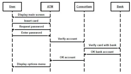
Throughout our paper we will consider the example of a simple ATM system. Let us focus on one scenario, i.e. one where a user inserts an ATM card into an ATM machine; after the card has been authenticated with the bank, a main menu is displayed. Fig. 2 illustrates the corresponding sequence diagram for the above scenario.
Fig. 2 Simple sequence diagram for an ATM
IV. DEPENDENCYDIAGRAMS
This section will explain the necessity of the dependency diagrams and will introduce them briefly.
A. Relationships between scenarios
One scenario represents only one particular “story” of the use of a system. For the complete description of the requirements specification, a number of scenarios are needed. These scenarios are not independent of each other, but several relationships and dependencies interconnect them.
If we consider the same example of an ATM system and two scenarios, one for creating a card with a bank, and another one for using the card for ATM operations, it is natural that the scenario of creating the card must precede the one of performing ATM operations. We cannot use an ATM card for various transactions unless we actually have a card. The above two scenarios must follow a strict order; in other words, there is a strict and clear relationship between them which cannot be ignored or altered.
Sequence diagrams, as representation of scenarios, show the objects and the way they communicate with each other. During the design phase, the behaviour of the object must appear clear, unambiguous. Different relationships between the scenarios where the object appears result in different overall behaviours of the respective object. It is therefore unified manner
REQUIREMENTS DESIGN TESTING SPECIFICATION
AUTOMATIC PROCESS
REQUIREMENTS
-clearer, better overview
[image:2.595.315.545.273.403.2]essential to know the correct relationship between scenarios, the one that reflects the requirements of the system.
The relationships can be classified from various points of view: with respect to their goals, in terms of used resources, the actors involved etc. However, we are concerned with how the behaviour of the objects involved is influenced by the relationships, because we intend to use this behaviour during the design phase. In a previous paper, we offered a classification from this point of view [7].
B. Normalization of scenarios
In their original form, as they are constructed from scenarios (use cases), two or more sequence diagrams can overlap, i.e. a common sequence of messages can be found in two (or more) sequence diagrams. In order to be able to express the relationships between them in an unambiguous manner, we believe it is essential to maintain the property of having distinct, individual sequence diagrams. Thus, before proceeding to expressing their relationships, we are going to
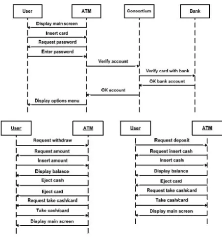
[image:3.595.313.540.164.409.2]remove the overlapping that might exist between them. We call this process normalization of the scenarios/sequence diagrams. Our purpose is to obtain disjoint sequence diagrams, i.e. individual, distinct sequence diagrams. In our ATM example, let us consider two scenarios: one for withdrawing cash and one for depositing cash (Fig. 3).
Fig. 3 Two scenarios for an ATM
We can notice that both scenarios suppose an initial set of operations where the card is validated with the bank and consortium of banks. More specifically, both sequence diagrams contain a series of 9 consecutive common messages, representing the overlapping that we are going to eliminate. We will separate the common messages into a new sequence diagram, appearing in Fig. 4. Consequently, from the original two sequence diagrams we have obtained three normalized sequence diagrams (Fig. 4).
Fig. 4 Normalized sequence diagrams
C. Dependency diagrams
In order to represent the relationships existing between various scenarios, we have introduced a new type of diagrams called dependency diagrams [7].
We will show an example here, applicable to the ATM system. In this example, the user approaches the ATM, inserts the card, the card is validated and the main options screen is displayed. This is considered the initial scenario, i.e.
Scenario_start. From this point, the user can select any of the three operations of withdrawing cash, depositing cash or transferring cash, that is either Scenario_withdraw or
Scenario_deposit or Scenario_transfer respectively.
We also assume that when the user changes his/her password (Scenario_chg_pass.), the scenario
Scenario_videotape takes place simultaneously, that is, the user is being videotaped during the operation of changing the password.
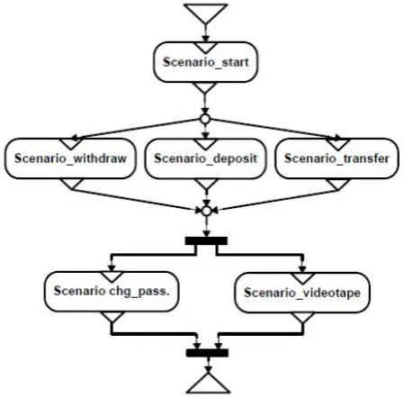
The dependency diagram showing how these scenarios are related to each other appears in Fig. 5.
This figure exemplifies succession (Scenario_start
precedes the other ones), the disjunction of three scenarios,
Scenario_withdraw, Scenario_deposit and
Scenario_transfer (any of them can be executed after
Scenario_start), as well as the conjunction of two scenarios,
[image:3.595.90.252.361.765.2]Scenario_start ;
(Scenario_withdraw ∨ Scenario_deposit ∨ Scenario_transfer) ;
(Scenario_chg_ pass. ∧ Scenario_videotape)
[image:4.595.63.288.167.388.2](";" is used to show succession, when one scenario follows another one, "∨" denotes disjunction, when only one scenario can occur at a certain moment, and "∧" shows conjunction, when scenarios occur simultaneously)
Fig. 5 Dependency diagrams involving six normalized scenarios for an ATM
V. GENERATIONOFTESTCASES
Jacobson, as early as 1992, stated that use cases are well suited to be used as test cases for integration testing [13] (without actually defining a method for achieving that). We are going to make use of the scenarios, as instances of use cases, to create our test cases.
We propose two phases for generating test cases: a) from individual scenarios;
b) from dependency diagrams.
As part of our methodology, we are performing the process of normalizing our scenarios (represented as sequence diagrams). By traversing various paths through each individual, normalized scenario, we can obtain a first set of what we call "primary" test cases. They are called primary because they refer to one small portion of the behaviour we need from our final product.
According to the way they were created, normalized scenarios are disjoint scenarios. Thus, the behaviour contained in one such normalized scenario will not be found again, as it is, in a different one. Consequently, once testing has been performed on this scenario, the same primary test will not be run again, i.e. the same behaviour will not be (needlessly) tested again.
Many approaches in test generation from behavioural models concentrate on test generation from state machine diagrams. We have also described how to obtain individual
state machine diagrams from a set of given sequence diagrams [10]. Many methods of path traversal in state machine diagrams have been proposed and any of them can be used to obtain the primary test cases [14].
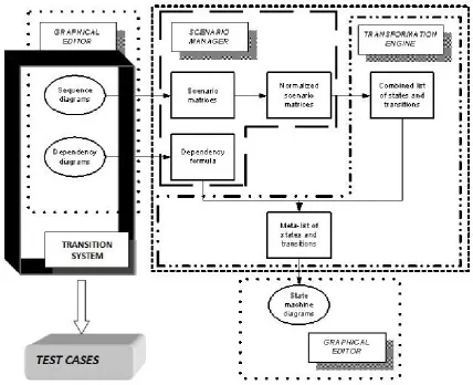
The system we proposed consists of the following main modules (shown in Fig.6):
- scenario manager - transformation engine - transition system
The scenario manager is the module where, from initial scenarios that describe the requirements, scenario matrices are created and then normalized. This module also creates a dependency formula from our dependency diagrams. This covers the requirements specification part of the software development process.
The transformation engine is the one that helps in generate a meta-list of states and transitions, useful in the creation of state machine diagrams. This covers part of the design phase. The transition system generates test cases by traversing various paths in the dependency diagrams. Considering the way we defined our dependency diagrams, one trace in one diagram can constitute a test case. With this transition system, we deal with the testing phase in the software development process.
Our system is in the process of being implemented. As such, the transition system’s implementation is not finalized yet. This transition system is mainly based on the dependency diagrams. They are the ones including complex behaviour, making sure that scenarios respect the way they are related and the way they depend on each other.
By traversing paths in the dependency diagrams, we can obtain "secondary" test cases. We call secondary the test cases which arise from more complex behaviour and which result as a combination of primary test cases.
Returning to our ATM example, we should first create test cases for verifying the behaviour in each of the normalized scenarios (and the corresponding state machine diagrams) is respected. (Three of these normalized scenarios have been represented in Fig. 4). Each test case corresponding to these scenarios will be a primary test case. For example, we can check that, as soon as we insert the card in the ATM, we are being asked for a password. If the card is verified, the main menu has to be displayed.
Next, we should obtain the secondary test cases, resulting from the dependency diagram given in Fig. 5. We can traverse several paths through this dependency diagram. During testing, we should check that all required behaviour is allowed. For instance, we can test whether, after the initial scenario, the three possibilities arise for the user to interact with the ATM, specifically withdrawing cash, depositing cash or checking current balance. We can also check whether video camera recording occurs at the same time with changing the password.
Such tests will only find whether behaviour that must be present is actually allowed. We can go further and start testing whether restricted behaviour is allowed or not. For example, we can test whether we can perform transactions like withdrawing cash (Scenario_withdraw) before authenticating our ATM card (Scenario_start).
through individual (normalized) scenarios allows us to obtain primary tests, traversing various paths in the dependency diagrams allows us to test more complex behaviour, i.e. obtain secondary tests.
VI. RELATEDWORK
A wide range of proposed approaches for extracting test cases from model-based specifications exists. It mainly uses a UML-based notations. Many such approaches base their test generation on state machines, like Antoniol et al. in [15] and Hartmann et al. in [15], who considered obtaining test sequences from UML statecharts by covering selected paths in a finite state machine.
Regarding the use of scenario-based testing, papers like that of Graubmann and Rudolph [17] use Message Sequence Charts, as well as High Level MSC (hMSC), along with sequence diagrams. The Cow Suite methodology [18] provides an integrated approach for generating and planning UML-based test suites for industrial applications.
Some approaches use both state machines and scenarios for test case generation. UMLAUT (Unified Modelling Language All pUrposes Transformer) [19] is a tool that transforms UML diagrams into an intermediate formal description understandable by the Test Generation and Verification (TGV) tool. SCENT ("A Method for SCENario-Based Validation and Test of Software "), presented in [14], creates scenarios in a structured way, formalizing them into statecharts. It also annotates the statecharts with helpful information for the test creation.
In their paper [20], S. Anand et. al classify the techniques used in test generation in the following categories: symbolic execution and program structural coverage testing, model-based test case generation, combinatorial testing, adaptive random testing as a variant of random testing, search-based testing. Numerous techniques by various authors are introduced; however, this survey does not cover certain techniques, like specification-based testing.
VII. CONCLUSIONSANDFUTUREWORK We proposed DePAT, a framework for specification-based test generation. Our framework offers an approach to software development which treats requirements specifications, design and testing in a unified manner. This is an ongoing work and we are currently in the process of implementing our final system. Once implemented, our system will be able to bring the tester one step closer to the testing of as many different behaviours as possible. One of the main benefits of our approach is allowing the possibility for the software developers to spend less time on test generation and more time on the requirements specifications. Moreover, the requirements specification, design and testing phases can be covered in a unified manner. This approach can help the developers avoid inconsistencies and can offer them a better overview of the system.
[image:5.595.69.498.59.407.2]Our future work, once the implementation of the system is concluded, will include conducting extensive testing and user evaluation.
REFERENCES
[1] Ian Sommerville, "Software Engineering", Addison Wesley, 9th edition,
2011
[2] E. W. Dijkstra, “Notes on structured programming”, T.H. – Report 70-WSK-03, 1970
[3] G. J. Myers, "The Art of Software Testing", Wiley & Sons, USA, 2004 [4] J. Zhang, X. Chen, X. Wang, “Path-oriented test data generation using symbolic execution and constraint solving techniques”, Proceedings of the Second International Conference on Software Engineering and Formal Methods, SEFM, 2004.
[5] B. Korel,, “Dynamic method for software test data generation”, Software Testing, Verification and Reliability, Vol. 2, Issue.4, 1992, pp. 203–213
[6] K.-H.Chang, J. H. Cross II, W. H. Carlisle, D. B. Brown, "A framework for intelligent test data generation", Journal of Intelligent and Robotic Systems, April 1992, Volume 5, Issue 2, pp 147-165
[7] S. Vasilache, "Dynamic Modeling in the Design Phase Using Dependency Diagrams", PhD Thesis, University of Tsukuba, 2007 [8] J. Rushby, "Automated Test Generation and Verified Software", in
Verified Software: Theories, Tools, Experiments, Bertrand Meyer and
Jim Woodcock (Eds.), Lecture Notes In Computer Science, Vol. 4171. Springer-Verlag, Berlin, Heidelberg, pp. 161-172
[9] P. Hsia, J. Samuel, J. Gao, D. Kung, Y. Toyoshima, C. Chen, "Formal approach to scenario analysis”, IEEE Software, 11( 2), 1994, pp. 33-41 [10] S. Vasilache, J. Tanaka, "Synthesis of State Machines from Multiple Interrelated Scenarios Using Dependency Diagrams," Journal of Systemics, Cybernetics and Informatics, Vol.3, No.3, 2006
[11] S. Freeman, N. Pryce, "Growing Object-Oriented Software, Guided by Tests", Addison-Wesley, USA, 2011
[12] C. Nebut, F. Fleurey, Y. L. Traon, J.M. Jezequel, "Automatic Test Generation: A Use Case Driven Approach", IEEE Transactions on Software Engineering, Vol. 32, No. 3, 2006
[13] I. Jacobson, M. Christerson, P. Jonsson, G. Övergaard, "Object Oriented Software Engineering: A Use Case Driven Approach", Amsterdam: Addison-Wesley, 1992
[14] J. Ryser, M. Glinz, "A scenario-based approach to validating and testing software systems using statecharts", Proc. 12th International Conference on Software and Systems Engineering and their Applications, 1999
[15] G. Antoniol, L. C. Briand, M. Di Penta, Y. Labiche, "A Case Study Using the Round-Trip Strategy for State-Based Class Testing", In Proc. of ISSRE, 2002
[16] J. Hartman C. Imoberdof, M. Meisenger "UML-Based Integration Testing", In ACM Proc. ISSTA 2000, Portland, 2000
[17] P. Graubmann, E. Rudolph, "HyperMSCs and Sequence Diagrams for use case modeling and testing", In Proceedings of UML 2000, volume LNCS Vol.1939, 2000, pp. 32–46
[18] F. Basanieri, A. Bertolino, E. Marchetti "The Cow Suite Approach to Planning and Deriving Test Suites in UML Project", In Fifth International Conference on the Unified Modeling Language - the Language and its applications(UML 2002), pp. 383–397, 2002 [19] UMLAUT Project, http://www.irisa.fr/UMLAUT/
[20] S. Anand, E. K. Burke, T. Y. Chen et. al. “An orchestrated survey of methodologies for automated software test case generation”, The Journal of Systems and Software, No. 86, 2013.