A Graphically Based Language for Constructing, Executing and Analysing
Models of Software Systems
Robert John Walters
Declarative Systems and Software Engineering Group,
Department of Electronics and Computer Science,
University of Southampton, Southampton, UK.
[email protected]
Abstract
With computer systems becoming ever larger and more complex, the cost and effort associated with their construction is increasing and the systems are now suffi-ciently complex that developers need help to analyse and understand them. However, at design time, when this understanding is crucial, the system is unavailable be-cause it has yet to be built. Formal, executable models can help with this problem by providing developers with a platform on which to establish the feasibility of a pro-posed design. However, commercial developers seem reluctant to employ this type of modelling in their design activity.
This paper describes a modelling tool in which the traditional model generation technique of writing “pro-gramming language like” code is replaced with a model generation tool which uses a graphical representation of models whilst retaining sufficient formality to permit the models to be executed, or converted into code for analy-sis by a traditional model checking tool.
1. Why build models of systems?
As computer and other systems continue to become lar-ger and more complex we need to find methods which enable us to manage this complexity. In most theatres where complexity is an issue, a winning technique has been to break the problem into pieces and then build the system by combining these pieces. In electronic and computer hardware this type of approach has been spec-tacularly successful [5, 12-14, 25]. The size of the pieces is a balance. Smaller pieces are easier to under-stand and handle, but more difficult to assemble into a useful whole. This technique is being adopted in soft-ware development as the need arises to build and man-age complex systems more effectively. However, these systems inhabit a world which is devoid of physical laws and so are not subject to the constraints which usually
apply. As a result, making software systems from col-lections of components is more difficult than in other disciplines.
There are two issues which need to be addressed where a system is to be constructed from components: first we need to connect the components together, then we have to get them to do what we want. The question of how to make pieces of software fit together has been the subject of considerable effort and systems and schemes exist which address these issues (COM, EJB, RMI, MSMQ…) [1, 4, 9, 18, 19, 23, 25, 27, 29]. Typi-cally, these arrangements work by managing and con-trolling the interfaces between components (as well as providing underlying support). By forcing components to conform to rules about how they interact with the oth-ers, these systems ensure that components do not dam-age each other and perform interactions which each should understand. We can see this type of considera-tion being applied in the physical world in things like the standardised plugs and sockets we use for domestic elec-tricity installations and other applications.
The other problem is more subtle and difficult. We need to ensure that the assembled system does what is required. Outside of software, this part of the problem of building from components is often quite simple. For example, the interface between a domestic appliance and the electricity supply actually only does one simple ac-tion (supplying power) so all that matters is that the con-nection is made between compatible interfaces.
inter-faces in this way is an enormous task and limits, if not prevents innovative use of components.
An alternative solution to this problem is to reason about and check the behaviour of a system as a separate activity. This needs to be done without access to the actual system, since this has yet to be built. Also, for anything but the most trivial of systems it is a daunting task and this is where models can help [2, 3, 6, 8, 10, 16, 17, 28]. These models do not need to replicate the be-haviour of the whole system. They only need to repre-sent the particular aspects of the system with which we are concerned. This enables us to abstract away unim-portant detail which in turn reduces the models’ com-plexity and the amount of time and effort required to construct them. However, we do need to analyse these models for "proper" behaviour. This analysis could be simple reasoning based on a diagram but, to be really useful, it needs to be more thorough - and for that we need models which have sufficient formality to permit analysis using techniques such as execution or model checking.
1.1. Existing modelling systems
Already, there exist a large number of modelling systems from informal diagramming techniques to mas-sive modelling languages with industrial strength tool support. The more formal systems [11, 20-22] have a good pedigree and typically also have both a formal ba-sis and enough expressive power for any situation. Some also have powerful, “industrial strength” support tools. However a common theme amongst these systems is their strong emphasis on the formal aspects of their description languages and they make few concessions to the needs of the working software engineer. As a result, there is a significant barrier to adoption of these tech-niques by novice users who find they need to invest a considerable amount of time and effort into a system before they are able to tackle real problems.
In contrast with the formal systems, there are dia-gram based system description techniques such as UML [7]. Their emphasis is on providing effective diagram-ming techniques for describing systems but the task of understanding and analysing the behaviour of the sys-tems they describe is largely left to the user.
2. RDT
This section describes RDT, a graphical language designed to address the problems outlined in the previ-ous section. Unlike other formal modelling systems, RDT does not attempt to be a powerful, feature rich modelling system. Instead it is deliberately simple to minimise the initial familiarisation required by a new user. It permits the description of systems built from
communicating instances of processes and has a collec-tion of tools with which these systems can be con-structed, executed and analysed.
2.1. Description of the language
The language uses the pi-calculus [22] as its founda-tion. It has a diagrammatic rather than textual represen-tation of models and builds upon the lessons learned from RolEnact and RaDraw [15, 24, 26]. The objective is to minimise the effort required by an unfamiliar user. Hence the language only implements a subset of the pi-calculus: the notions of processes, channels and communication along channels. Processes are able to communicate synchronously using channels in a manner similar to the pi-calculus, but in addition channels can be set to behave as fixed length buffers giving asynchro-nous communication between processes. This additional feature is provided based on the pragmatic observation that many systems under construction today use some form of asynchronous communication. A complete model for execution and analysis comprises a collection of process descriptions together with a description detail-ing the instances of these processes which exist in the model and how they are (initially) connected.
Processes have state. They proceed from one state to another by taking part in events. There are just three types of event, each of which is a type of communica-tion:
Send: A process executing a send event moves from
a named "before" state to a named "after" state, writing a value into a channel as this happens. The channel name specified in the definition of the event is the local name this process uses for that channel. Similarly, the value which is written into the channel is that referred to by the local name for the value concerned.
Receive: A receive event mirrors the send event.
The process moves from a named "before" state to a named "after" state and in doing so reads a value from a specified channel. The value read is given the name specified in the definition of the event. As with the send event, the name used for the channel and the value name are local to the process. Where a process reads from a channel into a value name for which it already knows a value, the new value replaces the existing one.
Create: A create event is a special form of a write
event. The difference concerns the value which is writ-ten into the channel. A new value (channel) is created immediately before being sent and associated with the name specified in the definition of the event. As with a receive, should the name already an associated value, this is overwritten.
The description of a particular instantiation of a col-lection of processes and their (initial) interconnections is referred to in RDT as a "model".
Instances: An "instance" is a single instance of a
type of process. Each process instance has its own name and is independent and distinct from other instances of the same type of process.
Connections: For process instances to
communi-cate, they need to know an appropriate value for a chan-nel which is known to both partners in the communica-tion. Process instances may receive the information which they need to interact with others (channel names) through "read" events or by knowing the information at the start of execution. Connections are the means by which this initial mutual knowledge of channels is in-jected into a model. These "connections" describe an association between pairs (or more) of local names used within instances of processes. Figure 3 shows a simple example of a model displayed in the model generating tool.
By default, names in processes have no value but when they do acquire one, either by virtue of a connec-tion established in the "model" before the start of execu-tion, or as a consequence of a read or create event, the value is a reference to (or name of) a channel. When the model is executed, channels provide the conduit between communicating processes. In contrast with the pi-calculus, communications in RDT need not be syn-chronous: the modeller is able to specify the length of channels when the model is to be executed. As a result, for the model execution tool, a simple sharing of names is not enough (because a channel may need to store val-ues which are written into it) so we have channels as a distinct type of entity in the system.
2.2. A mapping from RDT to Pi-calculus
The language of RDT uses a pictorial representation of processes and models in place of the more usual code and is divided into a collection of diagrams. There is one diagram for each type of process in the system which describes the behaviour of that process. There is a further diagram which describes the process instances in a particular model and the (initial) interconnections be-tween them.
This mapping between RDT and the pi-calculus is in two parts: a description of how an RDT process may be represented in the pi-calculus and then how the particu-lar description of a model corresponds to the pi-calculus. The remainder of this section assumes familiarity with the pi-calculus which is described comprehensively elsewhere [22] .
A process in RDT is described by its diagram. Whilst it would be possible to construct a description of our process as a single pi-calculus process, the task is
more manageable if a separate pi-calculus processes are written for each state which together describe the RDT process. We can exploit the fact that RDT processes have explicit names for their states by using these names for the pi-calculus processes in the form: Proc-essNameState. A final RDT state (one which is not the "before" state of any event) is equivalent to the pi-calculus event "0". This process does nothing and is often simply omitted from pi-calculus descriptions.
The processes for each state are constructed as fol-lows:
For a process P in state a which, after a “write” (placing the value z onto channel x) moves to state b:
b a xz.P
P =
A process P in state c which performs a "read" (reading a value from channel x to be called y) and moves to state d could be written as:
d c x(y).P
P =
A process P in state e which performs a "create" (generating a new name, k and writing it onto channel x) and then moves to state f would be:
f e ( k)xk.P
P = ν
A process P in state g which has no events which leave state g would be:
0 Pg =
Where there is more than one event leaving a state, the required process is a summation of each of the processes corresponding to each of the events.
For example; A process P in state i from which it is able to either write a value z on channel x followed by moving to state j or can read a value q on channel x followed by moving to state k would be written as:
k j
i xz.P x(q).P
P = +
Figure 1: Process A
[image:4.612.109.238.278.406.2]It is easiest to describe how this is achieved with an example. Consider a model consisting of a pair of proc-ess as described in Figure 1, Figure 2 and Figure 3. This shows a simple model in which there is just one instance each of two equally simple processes.
Figure 2: Process B
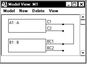
Process A creates a new channel which it calls C2 and writes this value (C2) into the channel it knows as C1. It then reads a value on the channel it knows as C2 which it calls C3 and stops.
Process B performs actions complementary to proc-ess A. It first reads a value, which it calls BC2, on the channel it knows as BC1. It then sends back the channel it now knows as BC2 on BC2 and stops.
The model M1 shows one instance of process A, called A1 and one instance of process B called B1. It also shows that, at the start of execution, the channel known to A1 as C1 is connected to (or shared with) the channel B1 knows as BC1.
Figure 3: Model M1
So, assuming synchronous communications, execu-tion of this model will consist of event E1 of process A1 and event EB1 of process B1 occurring as a pair fol-lowed by event E2 of process A1 and event EB2 of process B1. The system then stops.
Following the scheme outlined above, the two proc-esses A and B could be described as follows:
0 A A ). 3 C ( 2 C A A . 2 C 1 C ) 2 C ( A 3 state 3 state 2 state 2 state = = ν = 0 B B . 2 BC 2 BC B B ). 2 BC ( 1 BC B 3 Bstate 3 Bstate 2 Bstate 2 Bstate = = =
The remaining task is to create a composite process which has the behaviour of M1. For this we need to create a process which combines one instance each of process A and process B in such a way that the channel known to the instance of process A as C1 is the same channel as that known to the instance of process B as channel BC1. We could achieve this, for example by means of a re-naming BC1 to C1 in process B, but this is hard to generalise. An alternative is to parameterise processes A and B and then arrange the required "con-nections" by supplying suitable parameters:
0 ) 1 C ( A ) 1 C ( A ). 3 C ( 2 C ) 1 C ( A ) 1 C ( A . 2 C 1 C ) 2 C ( ) 1 C ( A 3 state 3 state 2 state 2 state = = ν = 0 ) 1 BC ( B ) 1 BC ( B . 2 BC 2 BC ) 1 BC ( B ) 1 BC ( B ). 2 BC ( 1 BC ) 1 BC ( B 3 Bstate 3 Bstate 2 Bstate 2 Bstate = = =
(
A(g)||B(g))
) g ( 1 M = ν
[image:4.612.102.247.572.685.2]2.3. The tools
The RDT language has a model generation tool which guides the modeller through the process of gener-ating a model and an execution tool with which the modeller is able to perform simple analysis of a model by animating it. Finally, there is a further tool which will generate a version of a model in PROMELA, the input language for the model checker, SPIN [17] with which the model can be subjected to exhaustive analysis. SPIN was selected as the target model checker for the language for two reasons: it is a highly respected model checker and its channel based scheme of inter-process communication is a close match for communications in RDT.
2.4. An Example: a Banking system.
[image:5.612.378.502.220.367.2]For an example, we consider a banking system which comprises two Bank processes, some Client proc-esses and at least one Clearing process. The three types of process behave as follows:
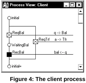
Figure 4: The client process
A Client is able to request a balance of their account from the Bank, or instruct the Bank to make a transfer.
Figure 5: The Bank process
A Bank process receives instructions from its Cli-ents. In the case of a balance request the Bank responds to the Client. Where the request is a transfer, it passes the instruction on to a Clearing process for action. The Bank also acts upon Debit and Credit instructions re-ceived from a Clearing process.
A Clearing process receives transfer instructions from Banks which it discharges by sending a Debit in-struction to one Bank and a Credit to the other.
[image:5.612.341.536.335.551.2]Descriptions of these three processes, built using the RDT model generation tool are shown in Figure 4, Figure 5 and Figure 6.
Figure 6: The clearing process
Figure 7: The example model during execu-tion
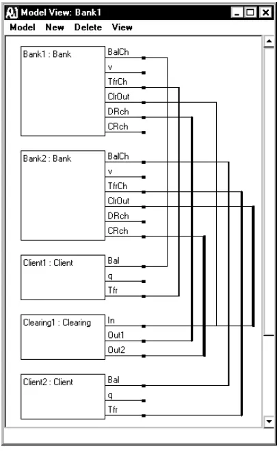
These completed process descriptions are then used to assemble a complete model whose behaviour we would like to analyse. Figure 8 shows the completed model.
[image:5.612.99.250.338.484.2] [image:5.612.68.281.523.667.2]proc-ess. When the channel length is set to zero, a process is only able to write into a channel if there is (at least one) other process which is waiting to read a value from that same channel, and the next event after the write must be a read from that same channel. In addition to the process windows there is a window for each of the channels in the model. When the length of the channels is not zero, these windows list those values which have been written into each channel but have yet to be read. The user has no interaction with the channel windows.
Figure 8: An example "model" diagram
3. Conclusion
Software systems are becoming larger and more complex and are increasingly being constructed, using components. This style of development is attractive because it divides the development task into more man-ageable parts and, where existing components are em-ployed, these often have a degree of maturity and reli-ability which is hard to impart to new code. We also have maturing technologies for assembling these com-ponents into complete systems, but these technologies do not address issues relating to the behaviour of the com-pleted system. We need techniques which will provide
answers to questions about the behaviour of a systems before the actual systems are available for testing.
The analysis of formal, executable models provides one route to insight about the likely behaviour of a com-pleted system and there are mature and powerful tools for building and analysing such models. However, we need to improve the way in which they are perceived by working software engineers. The language described in this paper, together with its tools demonstrates that it is feasible to build a modelling system with a simple inter-face which generates formal models of a type suitable for analysis by execution and model checking tech-niques.
4.
References:
[1] R. J. Allen and D. Garlan, "A Formal Basis for Ar-chitectural Connection," ACM Transactions on Software
Engineering and Methodology, vol. 6, pp. 213-249, 1997.
[2] M. Barjaktarovic, S. Chin and K Jabbour, "Formal Specification and Verification of Communication Protocols Using Automated Tools," presented at First IEEE Interna-tional Conference on Engineering of Complex Systems, Ft Lauderdale, Florida, 1995.
[3] B. Beitzer, "Cleanroom process model: A critical ex-amination," IEEE Software, 1997.
[4] D. Box and G. Booch, Essential COM: Addison Wesley, 1998.
[5] A. Carpenter and N. Messer, "The use of VHDL+ in the Specification Level Modelling of an Embedded System," presented at International Forum on Design Languages, Switzerland, 1998.
[6] E. M. Clarke, O. Grumberg, and D. E. Long, "Model Checking and Abstraction," ACM Transactions on
Pro-gramming Languages and Systems, vol. 16, pp. 1512-1542,
1994.
[7] M. Fowler, K. Scott, and G. Booch, UML Distilled
-Applying the standard Object Modelling language: Addison
Wesley, 1997.
[8] A. Gravell and P. Henderson, "Executing formal specifications need not be harmful," Software Engineering
Journal, vol. 11, 1996.
[9] D. N. Gray, J. Hotchkiss, S LaForge, A Shalit and T Weinberg, "Modern Languages and Microsoft's Component Object Model," Communications of the ACM, vol. 41, pp. 55-65, 1998.
[10] O. Grumberg and D. Long, "Model Checking and Modular Verification," ACM Transactions on Programming
Languages and Systems, vol. 16, pp. 843-871, 1994.
[11] P. H. Hartel, et al, "Questions and Answers About Ten Formal Methods," presented at 4th International Work-shop on Formal Methods for Industrial Critical Systems (FMICS99), Pisa, Italy, 1999.
[12] M. M. K. Hashmi, "Extending VHDL for Interface and System Specification," presented at Fall VIUF - VHDL for Power Users, 1998.
[13] M. M. K. Hashmi, VHDL+ Language Reference
[14] M. M. K. Hashmi and A. C. Bruce, "Design and Use of a System-Level Specification and Verification Methodol-ogy," presented at IEEE European Design Automation Con-ference, 1995.
[15] P. Henderson, Y. M. Howard, and R. J. Walters, "A tool for evaluation of the software development process,"
The Journal of Systems and Software, vol. 59, pp. 355-362,
2001.
[16] P. Henderson and R. J. Walters, "System Design Validation Using Formal Methods," presented at Tenth IEEE International Workshop on Rapid System Prototyping (RSP99), Clearwater, Florida, 1999.
[17] G. J. Holtzmann, "The Model Checker SPIN," IEEE
Transactions on Software Engineering, vol. 23, pp. 279-295,
1997.
[18] JavaSoft, "Java RMI specification," available from: http://www.javasoft.com, 1996.
[19] Microsoft, "Microsoft Message Queuing Services": Microsoft, 2001.
[20] R. Milner, Communication and Concurrency: Pren-tice Hall, 1989.
[21] R. Milner, "Elements of Interaction: Turing Award Lecture", vol. 36. Communications of the ACM, 1993.
[22] R. Milner, "The Polyadic pi-Calculus: a Tutorial," in
Logic and Algebra of Specification, F. L. Hamer, W. Brauer,
and H. Schwichtenberg, Eds.: Springer-Verlag, 1993. [23] Object Management Group, "Common Object Re-quest Broker: Architecture Specification,".
[24] K. T. Phalp, P. Henderson, G. Abeysinghe, and R. J. Walters, "RolEnact - Role Based Enactable Models of Busi-ness Processes," Information And Software Technology, vol. 40, pp. 123-133, 1998.
[25] D. S. Platt, Understanding COM+: Microsoft Press, 1999.
[26] RolEnact. Available from
http://www.ecs.soton.ac.uk/~ph/RolEnact, 1999.
[27] R. Sessions, COM and DCOM - Microsoft's Vision
for Distributed Computing: Wiley Computer Publishing,
1998.
[28] K. Sullivan, J. Socha, and M. Marchukov, "Using Formal Methods to Reason about Architectural Standards," presented at 19th International Conference on Software En-gineering, Boston, 1997.