NONRESIDENT
TRAINING
COURSE
April 1994
Electronics Technician
Volume 5—Navigation Systems
NAVEDTRA 14090
PREFACE
By enrolling in this self-study course, you have demonstrated a desire to improve yourself and the Navy.
Remember, however, this self-study course is only one part of the total Navy training program. Practical
experience, schools, selected reading, and your desire to succeed are also necessary to successfully round
out a fully meaningful training program.
COURSE OVERVIEW: In completing this nonresident training course, you should be able to: Identify
the primary navigation systems used by Navy surface vessels; identify the basic components of and explain
the basic operation of the Ship’s Inertial Navigation System (SINS); identify the basic components of and
explain the operation of the U.S. Navy Navigation Satellite System (NNSS); identify the basic components
of and explain the operation of the NAVSTAR Global Positioning System (GPS); and identify the basic
components of and explain the operation of the Tactical Air Navigation (TACAN) system.
THE COURSE: This self-study course is organized into subject matter areas, each containing learning
objectives to help you determine what you should learn along with text and illustrations to help you
understand the information. The subject matter reflects day-to-day requirements and experiences of
personnel in the rating or skill area. It also reflects guidance provided by Enlisted Community Managers
(ECMs) and other senior personnel, technical references, instructions, etc., and either the occupational or
naval standards, which are listed in the
Manual of Navy Enlisted Manpower Personnel Classifications
and Occupational Standards
, NAVPERS 18068.
THE QUESTIONS: The questions that appear in this course are designed to help you understand the
material in the text.
VALUE:
In completing this course, you will improve your military and professional knowledge.
Importantly, it can also help you study for the Navy-wide advancement in rate examination. If you are
studying and discover a reference in the text to another publication for further information, look it up.
1994 Edition Prepared by
ETC(SW/AW) James R. Branch
Published by
NAVAL EDUCATION AND TRAINING
PROFESSIONAL DEVELOPMENT
AND TECHNOLOGY CENTER
Sailor’s Creed
“
I am a United States Sailor.
I will support and defend the
Constitution of the United States of
America and I will obey the orders
of those appointed over me.
I represent the fighting spirit of the
Navy and those who have gone
before me to defend freedom and
democracy around the world.
I proudly serve my country’s Navy
combat team with honor, courage
and commitment.
CONTENTS
CHAPTER Page
1. SURFACE NAVIGATION SYSTEMS . . . 1-1
2. TACTICAL AIR NAVIGATION . . . 2-1
APPENDIX
I. List of Acronyms . . . AI-1 II. References . . . AII-l
INDEX . . . Index-1
SUMMARY OF THE ELECTRONICS TECHNICIAN
TRAINING SERIES
This series of training manuals was developed to replace the Electronics
Technician 3 & 2 TRAMAN. The content is directed toward personnel working
toward advancement to Electronics Technician Second Class.
The nine volumes in the series are based on major topic areas with which the ET2 should be familiar, Volume 1, Safety, provides an introduction to general safety as it relates to the ET rating. It also provides both general and specific information on electronic tag-out procedures, man-aloft procedures, hazardous materials (i.e., solvents, batteries, and vacuum tubes), and radiation hazards. Volume 2,
Administration, discusses COSAL updates, 3-M documentation, supply paperwork,
INSTRUCTIONS FOR TAKING THE COURSE
ASSIGNMENTS
The text pages that you are to study are listed at
the beginning of each assignment. Study these
pages carefully before attempting to answer the
questions. Pay close attention to tables and
illustrations and read the learning objectives.
The learning objectives state what you should be
able to do after studying the material. Answering
the questions correctly helps you accomplish the
objectives.
SELECTING YOUR ANSWERS
Read each question carefully, then select the
BEST answer. You may refer freely to the text.
The answers must be the result of your own
work and decisions. You are prohibited from
referring to or copying the answers of others and
from giving answers to anyone else taking the
course.
SUBMITTING YOUR ASSIGNMENTS
To have your assignments graded, you must be
enrolled in the course with the Nonresident
Training Course Administration Branch at the
Naval Education and Training Professional
Development
and
Technology
Center
(NETPDTC). Following enrollment, there are
two ways of having your assignments graded:
(1) use the Internet to submit your assignments
as you complete them, or (2) send all the
assignments at one time by mail to NETPDTC.
Grading on the Internet:
Advantages to
Internet grading are:
•
you may submit your answers as soon as
you complete an assignment, and
•
you get your results faster; usually by the
next working day (approximately 24 hours).
In addition to receiving grade results for each
assignment, you will receive course completion
confirmation once you have completed all the
assignments.
To
submit
your
assignment
answers via the Internet, go to:
http://courses.cnet.navy.mil
Grading by Mail: When you submit answer
sheets by mail, send all of your assignments at
one time. Do NOT submit individual answer
sheets for grading. Mail all of your assignments
in an envelope, which you either provide
yourself or obtain from your nearest Educational
Services Officer (ESO). Submit answer sheets
to:
COMMANDING OFFICER
NETPDTC N331
6490 SAUFLEY FIELD ROAD
PENSACOLA FL 32559-5000
Answer
Sheets:
All
courses
include
one
“scannable” answer sheet for each assignment.
These answer sheets are preprinted with your
SSN, name, assignment number, and course
number. Explanations for completing the answer
sheets are on the answer sheet.
Do not use answer sheet reproductions: Use
only
the
original
answer
sheets
that
we
provide—reproductions will not work with our
scanning equipment and cannot be processed.
Follow the
instructions
for
marking your
answers on the answer sheet. Be sure that blocks
1, 2, and 3 are filled in correctly. This
information is necessary for your course to be
properly processed and for you to receive credit
for your work.
COMPLETION TIME
PASS/FAIL ASSIGNMENT PROCEDURES
If your overall course score is 3.2 or higher, you
will pass the course and will not be required to
resubmit assignments. Once your assignments
have been graded you will receive course
completion confirmation.
If you receive less than a 3.2 on any assignment
and your overall course score is below 3.2, you
will be given the opportunity to resubmit failed
assignments.
You
may
resubmit
failed
assignments only once. Internet students will
receive notification when they have failed an
assignment--they may then resubmit failed
assignments on the web site. Internet students
may
view
and
results
for
failed
assignments from the web site. Students who
submit by mail will receive a failing result letter
and a new answer sheet for resubmission of each
failed assignment.
COMPLETION CONFIRMATION
After successfully completing this course, you
will receive a letter of completion.
ERRATA
Errata are used to correct minor errors or delete
obsolete information in a course.
Errata may
also be used to provide instructions to the
student.
If a course has an errata, it will be
included as the first page(s) after the front cover.
Errata for all courses can be accessed and
viewed/downloaded at:
http://www.advancement.cnet.navy.mil
STUDENT FEEDBACK QUESTIONS
We value your suggestions, questions, and
criticisms on our courses. If you would like to
communicate with us regarding this course, we
encourage you, if possible, to use e-mail. If you
write or fax, please use a copy of the Student
Comment form that follows this page.
For subject matter questions:
E-mail:
n315.products@cnet.navy.mil
Phone:
Comm: (850) 452-1001, Ext. 1713
DSN: 922-1001, Ext. 1713
FAX: (850) 452-1370
(Do not fax answer sheets.)
Address:
COMMANDING OFFICER
NETPDTC N315
6490 SAUFLEY FIELD ROAD
PENSACOLA FL 32509-5237
For
enrollment,
shipping,
grading,
or
completion letter questions
E-mail:
fleetservices@cnet.navy.mil
Phone:
Toll Free: 877-264-8583
Comm: (850) 452-1511/1181/1859
DSN: 922-1511/1181/1859
FAX: (850) 452-1370
(Do not fax answer sheets.)
Address:
COMMANDING OFFICER
NETPDTC N331
6490 SAUFLEY FIELD ROAD
PENSACOLA FL 32559-5000
NAVAL RESERVE RETIREMENT CREDIT
Student Comments
Course Title:
Electronics Technician, Volume 5—Navigation Systems
NAVEDTRA:
14090
Date:
We need some information about you:
Rate/Rank and Name: SSN: Command/Unit
Street Address: City: State/FPO: Zip
Your comments, suggestions, etc.:
Privacy Act Statement: Under authority of Title 5, USC 301, information regarding your military status is requested in processing your comments and in preparing a reply. This information will not be divulged without written authorization to anyone other than those within DOD for official use in determining performance.
CHAPTER 1
SURFACE NAVIGATION SYSTEMS
INTRODUCTION
Today’s Navy uses various navigational systems in the fleet. As an ET, you will be responsible for maintaining these systems.
In this volume, we will cover navigation fundamentals, the Ship’s Inertial Navigation System, Navy Satellite Navigation System, NAVSTAR Global Positioning System, fathometers, and TACAN. Let’s start with navigation fundamentals.
NAVIGATION FUNDAMENTALS
In simple terms, navigation is a method of getting from one known point to some distant point. Piloting, celestial navigation, and radio navigation are the commonly used methods. In this chapter, we will discuss radio navigation and its components: dead reckoning, electronic navigation, and tactical navigation. The tactical use of NTDS data (tactical navigation) was covered in v o l u m e 3 ,
Communications Systems. However, we will review
it briefly here to help you see how it fits into radio navigation. We will then discuss dead reckoning and electronic navigation in more detail.
TACTICAL NAVIGATION
You must understand the difference between navigation in the traditional sense and tactical navigation. Traditional navigation and piloting are concerned primarily with safe maneuvering of the ship with respect to hazards such as shoals, reefs, and so forth. Tactical navigation is not directly concerned wit h maneuvering the ship in navigable waters. For the purposes of tactical navigation, absolute position is unimportant except to the extent that it supports determining the relative position of hostile targets and friendly cooperating platforms.
Remember, tactical navigation deals primarily with fixing the location of the platform to (1) enable installed weapon systems to function against intended targets, (2) prevent ownship loss to or interference with friendly weapon systems, and (3) coordinate ownship weapons systems with those of other platforms to achieve maximum effect.
In tactical navigation, navigation data is used by combat systems, including NTDS, to ensure accuracy in target tracking. Ship’s movements are automatically recorded by computer programs for applications such as gun laying calculations and Link 11 position reporting. Ship’s attitudes (pitch, roll, and heading) are transmitted to various display and user points, and electronic or mathematical computer stabilization is accomplished, depending on the system. For example, pitch and roll are used by NTDS, missile, sonar, gun, and TACAN systems for stabilization data and reference. Heading is used by the EW direction finding, sonar, and radar systems for true and relative bearing display. Ship’s navigation and attitude data are provided by various equipment, depending on ship class.
DEAD RECKONING
inertial navigation system that measures the ship’s motion in several planes and integrates the results with a high degree of accuracy. Although the methods of dead reckoning may vary, they all share the following characteristics: (1) the accuracy of the estimated position never exceeds the navigation method used to obtain the last fix, and (2) the accuracy of the estimated position deteriorates over time.
ELECTRONIC NAVIGATION
Simply put, electronic navigation is a form of piloting. Piloting is the branch of navigation in which a ship’s position is determined by referring to landmarks with known positions on the earth. These reference points may be bearing and distance to a single object, cross bearings on two or more objects, or two bearings on the same object with a time interval in between.
Position in electronic navigation is determined in practically the same way as piloting, though there is one important difference—the landmarks from which the ship’s position is determined do not have to be visible from the ship. Instead, their bearings and ranges are obtained by electronic means.
The advantages of electronic navigation are obvious. A ship’s position maybe fixed electronically in fog or heavy weather that makes it impossible to take visual fixes. Also, an electronic fix can be based on stations far beyond the range of any local bad weather.
Since electronic navigation is the primary form of navigation in today’s Navy, the rest of this chapter will deal with electronic navigation and the roles played by the following systems:
1. Long Range Aid to Navigation (LORAN)
2. VLF Radio Navigation (OMEGA)
3. Ship’s Inertial Navigation System (SINS)
4. Navy Navigation Satellite System (NNSS)
5. NAVSTAR Global Positioning System (GPS)
We will also briefly discuss navigation radar, surface search radar, and fathometers.
We will cover TACAN in chapter 2.
LORAN/OMEGA—TRANSITION AND BASIC OPERATION
LORAN and OMEGA have been the “workhorse” systems for many years. However, they are being phased out. Based on the DOD policy statement reprinted below and because you may see a civilian version aboard your ship from time to time, we will simply give you an overview of the two systems. In
accordance with the 1992 Federal Radio navigation Plan (FRP), NAVSTAR will become the primary reference navigation system for surface ships, submarines, and aircraft. The DOD requirement for LORAN-C and OMEGA will end 31 December 1994 and TRANSIT will be terminated in DECEMBER 1996. Land-based TACAN and VOR/DME are to be phased out by the year 2000.
LORAN BASICS
OMEGA BASICS ADVANTAGES
O M E G A i s a h y p e r b o l i c p h a s e - d i f f e r e n c e measurement system. Hyperbolic navigation involves comparing the phase angles of two or more radio signals that are synchronized to a common time base. B y m o v i n g t h e O M E G A r e c e i v e r ( b y s h i p ’ s movement) and keeping the transmitter stations on frequency with a constant difference in time and phase, the system can measure the relative phase relationship between two stations to determine a line of position (LOP) for the ship. The relative phase angle measured between paired transmitting stations depends upon the distance of the receiver from each t r a n s m i t t e r .
It is important to understand that a minimum of two transmitters are required to obtain a basic position fix. Three or four are necessary to obtain an accurate fix. Unfortunately, there are many times in which only two transmitters are available but three are desired. One way around this problem is to use the receiver oscillator as a third, or “phantom,” transmitter. By setting the receiver oscillator to the frequency transmitted by each of the two OMEGA transmitters, the operator can compare the actual transmitted frequencies to the frequencies of the two received signals. This comparison provides two phase angles. The operator can then compare the two phase angles to determine a third phase angle. The three phase angles will yield a fix as accurate as a fix determined from three actual transmitters.
SHIP’S INERTIAL NAVIGATION SYSTEM
The Ship’s Inertial Navigation System (SINS) is a navigation system that (after initial latitude, longitude, heading, and orientation conditions are set into the system) continuously computes the latitude and longitude of the ship by sensing acceleration. This is in contrast to OMEGA and LORAN, which fix the ship’s position by measuring position relative to some known object. SINS is a highly accurate and sophisticated dead reckoning device. Let’s look at some of the advantages of using the SINS.
SINS has a major security advantage over other types of navigation systems because it is completely independent of celestial, sight, and radio navigation aids. In addition, SINS has the following advantages:
1. It is self-contained.
2. It requires minimal outside information.
3. It cannot be jammed.
4. It is not affected by adverse weather conditions.
5. It does not radiate energy.
6. It is not detectable by enemy sensors.
Now that we have seen the advantages of this system, let’s look at its basic components.
BASIC COMPONENTS
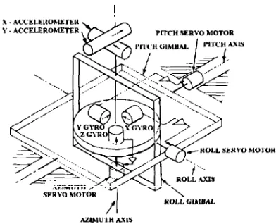
[image:13.612.345.541.495.654.2]Look at figure 1-1. The basic components of an inertial navigation system are accelerometers, gyroscopes, servo systems, and the computers (not shown). Accelerometers measure changes in speed or direction along the axis in which they lie. Their output is a voltage, or series of pulses (digital), proportional to whatever acceleration is experienced.
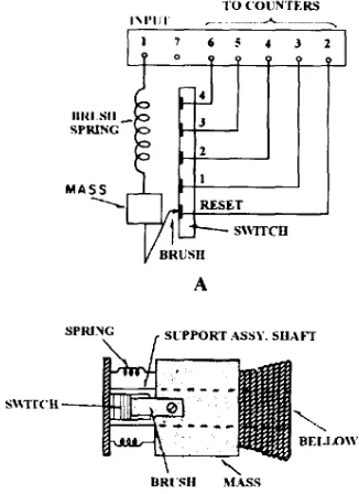
Figure 1-2 shows an E-transformer accelerometer, while figure 1-3 shows a pulse counting accelerometer. Two accelerometers (orientated North-South and East-West, respectively) are mounted on a gyro-stabilized platform to keep them in a horizontal position despite changes in ship’s movement. The accelerometers are attached to the platform by an equatorial mount (gimbal) whose vertical axis is misaligned parallel to the earth’s polar axis. This permits the N-S accelerometer to be aligned along a longitude meridian and the E-W accelerometer to be aligned along a latitude meridian.
Figure 1-2.—E-transformer accelerometer.
A three-gyro stabilized platform is maintained in the horizontal position regardless of the pitch, roll, or yaw of the ship. Figure 1-4 shows a gimbal-mounted gyro. Ship’s heading changes cause the gyro signals to operate servo system motors, which in turn keep the platform stabilized. High-performance servo systems keep the platform stabilized to the desired accuracy. (You will find in-depth information on accelerometers, gyros, and servo systems in NEETS Module 15, Principles of Synchros, Servos, and
Gyros.).
Maintaining this accuracy over long periods of time requires that the system be updated periodically. This is done by resetting the system using information from some other navigation means; i.e., electronic, celestial, or dead reckoning.
Figure 1-3.—Pulse counting accelerometer.
[image:14.612.337.546.473.665.2]Several models of SINS are in use. In general, AN/WSN-2 systems are installed on auxiliary ships, AN/WSN-2A systems are installed on submarines, and AN/WSN-5 systems are installed or being installed on surface combatants. In the following paragraphs, you will be introduced to the AN/WSN-5 SINS and its advantages over these earlier systems.
AN/WSN-5 SINS Ship’s north, east, and vertical velocity components
The AN/WSN-5 is a stand-alone set that replaces the MK 19 MOD 3 gyrocompass in the following class ships: CG 16, CG 26, CGN 9, CGN 25, CGN 35, CGN 36, CGN 38 (except for CGN 41), DDG 37, DD 963, and LHA 1. It also replaces the AN/WSN-2 stabilized gyrocompass set in DDG 993, DD 997, and CGN 41 class ships.
Functional Description
The AN/WSN-5 has the same output capabilities as the AN/WSN-2. It uses an accelerometer-controlled, three axis, gyro-stabilized platform to provide precise output of ship’s heading, roll, and pitch data in analog, dual-speed synchro format to support ship’s navigation and fire control systems. Ship’s heading and attitude data are continually and automatically derived while the equipment senses and processes physical and electrical inputs of sensed motion (inertial), gravity, earth’s rotation, and ship’s speed. The equipment has an uninterruptible backup power supply for use during power losses, and built-in test equipment (BITE) to provide fault isolation to the module/assembly level.
Characteristics
In addition to the common functions described above, the AN/WSN-5 adds an increased level of performance to serve as an inertial navigator and provides additional analog and digital outputs. Additional data provided includes position, velocity, attitude, attitude rates, and time data in both serial and parallel digital formats, providing a variety of interfaces. The AN/WSN-5 commonly exists in a dual-system configuration on surface combatants. Some examples of AN/WSN-5 digital data outputs a r e :
1. Two Naval Tactical Data System (NTDS) serial channels transmitting:
Ship’s heading, roll, and pitch
Ship’s heading rate, roll rate, and pitch rate
Ship’s latitude, longitude, and GMT
2. Two MIL-STD-1397 NTDS type D high-level channels to an external computer
3. One MIL-STD-1397 NTDS type A slow, 16-bit, parallel input/output channel to a Navigation Satellite (NAVSAT) receiver AN/WRN-5A, Global Positioning System (GPS) receiver AN/WRN-6, or I/O console.
4. One serial AN/WSN-5 to AN/WSN-5 digital link that provides alignment data, Navigation Satellite (NAVSAT) fix data, calibration constant data, and other navigation data to the remote AN/WSN-5.
5, An additional variety of input/output NTDS channels, depending on which field changes are installed.
SATELLITE NAVIGATION SYSTEMS
Scientists realized that navigation based on satellite signals was possible after listening to the beep generated by Russia’s first artificial satellite, Sputnik I. They noticed a shift in the received radio frequency signals as the satellite passed by. This shift, known as the Doppler effect, is an apparent change in a received frequency caused by relative motion between a transmitter and a receiver. As the distance between the transmitter and the receiver decreases, the received frequency appears to increase. As the distance increases, the received frequency appears to decrease.
With this discovery, scientists were able to show that by accurately measuring a satellite’s Doppler shift pattern, they could determine the satellite’s orbit. They then determined that by using a known satellite’s orbit, a listener could determine his own position on the earth’s surface by observing the satellite’s Doppler pattern.
System (NNSS) became operational. This system is an all-weather, highly accurate navigation aid, enabling navigators to obtain accurate navigation fixes from the data collected during a single pass of an orbiting satellite.
The following paragraphs describe the NNSS, its satellites, Doppler principles, system accuracy , and two common shipboard equipments—the AN-WRN-5( V) and the AN/SRN-19(V)2.
NAVY NAVIGATION SATELLITE SYSTEM
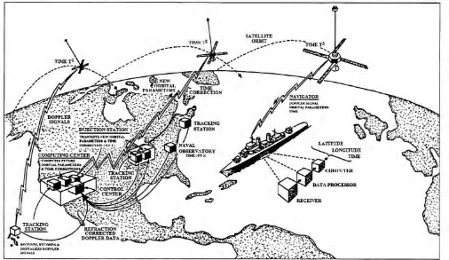
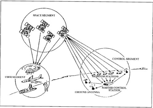
This highly accurate, world-wide, all weather system enables navigators to obtain fixes approximately every 2 hours, day or night. Looking at figure 1-5, you can see that it consists of earth-orbiting satellites, tracking stations, injection stations, the U.S. Naval Observatory, a computing center, and shipboard navigation equipment.
System Satellites
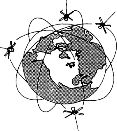
Satellites are placed in a circular polar orbit, as illustrated in figure 1-6, at an altitude of 500 to 700 (nominally 600) nautical miles. Each satellite orbits in approximately 107 minutes, continually transmitting phase-modulated data every 2 minutes on two rf carriers. This data includes time synchronization signals, a 400-Hz tone, and fixed and variable parameters that describe the satellite’s orbit.
[image:16.612.54.560.339.632.2]The fixed parameters describe the nominal orbit of the satellite. Variable parameters (small corrections to the fixed parameters) are transmitted at two-minute intervals and describe the fine structure of the satellite orbit. The satellite memory stores sufficient variable parameters to provide the two-minute orbit corrections for 16 hours following injection of fresh data into the memory. Since data injections occur about every 12 hours, the satellite memory will not
Figure 1-6.—Satellite orbits.
run out. Each two-minute long satellite message is timed so that the end of the 78th bit, which is the last bit of the second synchronization signal, coincides with even 2 minutes of Greenwich mean time (GMT). Thus the satellites can also be used as an accurate time reference by all navigators equipped with a satellite navigation set.
Each satellite is designed to receive, sort, and store data transmitted from the ground and to retransmit this data at scheduled intervals as it circles the earth. Each satellite tells users which satellite it is, the time according to the satellite clock, and its present location. With this information, the user’s navigation set can determine exactly where the satellite is, one of the necessary steps toward determining a precise navigational position.
Tracking Stations
Tracking s t a t i o n s a r e l o c a t e d i n M a i n e , Minnesota, California, and Hawaii. As each satellite passes within radio line-of-sight (los) of each of these tracking stations, it is tracked to accurately determine its present and future orbits. Just before predicted satellite acquisition, the tracking station’s antenna is pointed toward the satellite to acquire its signals. As the satellite rises above the horizon, the tracking antenna continues to follow the satellite’s predicted
path until the radio receiver in the tracking station locks on to the satellite’s transmitted signal. The receiver processor and data processing equipment decode and record the satellite message. The Doppler tracking signal is digitized and sent with the satellite time measurements to the computing center, via a control center, where a refined orbit is calculated.
The tracking stations maintain highly stable oscil-lators that are continually compared against a WWV transmitted frequency standard. In addition, the Naval Observatory sends daily messages that give the error in the transmitted standard. The Naval observatory error is then added to the data obtained from the frequency standard, and corrections are made to the station oscillators. The station oscillators are used to drive station clocks, which are compared with the time marks received from the satellite. This time data is transmitted by the tracking stations to the control center, where the satellite clock error is calculated and the necessary time correction bits are added or deleted in the next injection message to the satellite.
Computing Center
The central computing center continually accepts satellite data inputs from the tracking stations and the Naval Observatory. Periodically, to obtain fixed orbital parameters for a satellite, the central computing center computes an orbit for each satellite that best fits the Doppler curves obtained from all tracking stations. Using this computed orbital shape, the central computing center extrapolates the position of the satellite at each even 2-minutes in universal time for the 12 to 16 hours subsequent to data injection. These various data inputs are supplied to the injection stations via the control center, as is data on the nominal space of the orbits of the other satellites, commands and time correction data for the satellite, and antenna pointing orders for the
injection
station antennas.
Injection Station
transmission
to
the satellite. Just before satellite time-of-rise, the injection station’s antenna is pointed to acquire, lock on, and track the satellite through the pass. The receive equipment receives and locks on to the satellite signals and the injection station transmits the orbital data and appropriate commands to the satellite. Transmission to the satellite is at a high bit rate, so injection is completed in about 15 seconds.The message transmitted by the satellite immediately after an injection contains a mix of old and new data. The injection station compares a readback of the newly injected data with data the satellite should be transmitting as a check for errors. If no errors are detected, injection is complete, If one or more errors are detected, injection is repeated at two-minute intervals (updating the variable parameters as necessary) until satellite transmission is verified as being correct.
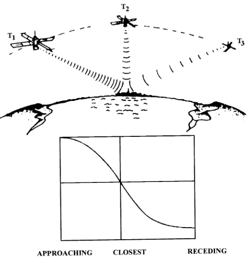
DOPPLER PRINCIPLES
Look at figure 1-7. Stable oscillator frequencies radiating from a satellite coming toward the receiver are first received (T1) at a higher frequency than t r a n s m i t t e d , b e c a u s e o f t h e v e l o c i t y o f t h e approaching satellite. The satellite’s velocity produces accordion-like compression effects that squeeze the radio signals as the intervening distance shortens. As the satellite nears its closest point of approach, these compression effects lessen rapidly, until, at the moment of closest approach (T2), the cycle count of the received frequencies exactly matches those which are generated. As the satellite passes beyond this point and travels away from the receiver (T3), expansion effects cause the received frequencies to drop below the generated frequencies proportionally to the widening distance and the speed of the receding satellite.
FACTORS AFFECTING ACCURACY
Measurement of Doppler shift is complicated by the fact that satellite transmissions must pass through the earth’s upper atmosphere on their way from space to the receiver. Electrically charged particals in the i o n o s p h e r i c l a y e r c a u s e r e f r a c t i o n o f t h e s e transmissions. To solve this problem, the satellites are
designed to broadcast on two frequencies (150 and 400 MHz). The receiver measures the difference in refraction between the two signals and supplies this measurement to the computer. The computer uses this refraction measurement as part of its computation to obtain accurate fixes. The most serious problem affecting accuracy is the effect of uncertainty in the vessel’s velocity on the determination of position. Velocity computation problems are inherent in the system. Position error resulting from an error in velocity measurement is somewhat dependent on the geometry of the satellite pass. You can expect about a 0.2 mile error for every one-knot error in the vessel’s velocity. Knowing this, you can see that precision navigation of a moving vessel requires an accurate measurement of the velocity of the moving vessel, such as is provided by a good inertial navigation system (See the section on Ship’s Inertial Navigation System.). In general, intermittent precision navigation fixes would not be of extreme value for a moving vessel unless it had some means of interpolating between these precision fixes. A good inertial navigation system provides such a means, and simultaneously provides the accurate velocity measurements required to permit position fixes with the NNSS.
Figure 1-7.—Doppler shift relative to satellite transmitted frequency.
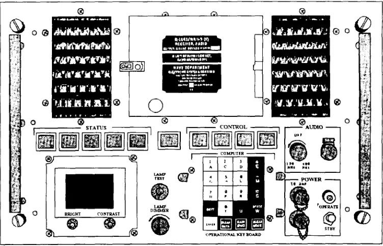
The two most common satellite navigation AN/WRN-5(V) RADIO NAVIGATION SET systems used by the Navy are the AN/WRN-5 and the
designed to recieve and phase track signals transmitted by satellites of the NNSS. These signals are processed to obtain navigation information that is monitored on video displays and used elsewhere for ship navigation.
The AN/WRN-5 is designed to be used in various configurations as described below. Each of these configurations is defined by options in external equipment used or variations in inputs and outputs. The options available for alternative configurations are:
1.
2.
3.
4.
5.
6.
Teleprinter, ASR-33
Additional remote video displays, IP-1154(U)
Frequency standard, AN/URQ-10/23 (external reference)
Dual antennas (separate 400-MHz and 150-MHz antennas)
Input/output bus
External lock indicator
7. 100-KHz output
The functional elements of the AN/WRN-5 include the following components:
1.
2.
3.
4.
5.
6.
7.
8.
Preamplifier unit
Built-in two channel receiver
Built-in expanded data processor unit
(XPDU) with 16K word memory
Front panel keyboard for operator-to-system interface
Front panel magnetic tape cassette transport with read/write capability for OPNAV program loading or data recording
Front panel video display for system to operator input/output
Remote video monitor
[image:20.612.122.498.431.673.2]Built-in synchro-to-digital convertor for interface with the ship’s speed and heading sensors to provide dead reckoning capability
and accurate satellite position fixes during ship maneuvers
6. Displays inputted speed and heading.
7. Displays inputted set and drift. 9. Optional addition of a teleprinter
8. Displays data on a tracked satellite. The combination of fictional elements in the
AN/WRN-5 provides many capabilities including automatic storage of satellite information, time-ordered alerts for up to eight satellites, and built-in self test. The front panel video display provides current time, latitude/longitude, dead reckoning position (automatically updated by satellite fixes), and satellite tracking information such as fix merit and satellite alerts. You will find specific information on the capabilities of this navigation set in the AN/WRN-5 operation and maintenance technical manual.
9. Performs a self-test of computer functions [limited to verification of the digital circuitry).
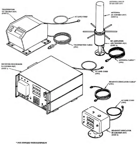
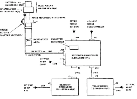
The AN/SRN-19(V)2 consists of the major components shown in figure 1-9.
Figure 1-10 shows a simplified block diagram of this system. The following paragraphs describe these components.
ANTENNA GROUP OE-284/SRN-19(V) AN/SRN-19(V)2 RADIO NAVIGATION SET
The AN/SRN-19(V)2 is an automatic shipboard navigation set that provides a continuous display of the ship’s position. The ship’s position, which is obtained by dead reckoning on true speed and heading, is periodically corrected by satellite fixes. Specifically, the navigation set can perform the following functions:
1. After each successful satellite pass, computes and displays the present location of the ship to a nominal at-sea accuracy of 0.25 nautical mile.
The antenna group consists of the AS-3330/SRN-19(V) antenna and AM-7010/SRN-AS-3330/SRN-19(V) rf amplifier
Antenna
The antenna is a linear, vertically-polarized type that receives rf signals transmitted by the satellite. Its horizontal pattern is omnidirectional; its vertical pattern varies approximately 11 dB from 10 to 70 degrees above the horizontal plane.
Rf Amplifier
Note: Accuracy of the fix is affected by high The rf amplifier provides initial amplification of sunspot activity. During these periods, nominal the 400-MHz satellite signals from the antenna and at-sea accuracy may degrade to approximately then sends them, via rf coaxial cable, to the receiver 0.5 nautical mile. for further amplification and processing. The rf amplifier consists of a bandpass filter module, a 400-2. Dead reckons between satellite fixes MHz amplifier, and a dc block module.
3. Computes and displays the range and bearing RECEIVER-PROCESSOR R-2135/SRN-19(V)
from the present position to any destination using the
great circle program. The receiver-processor consists of a single channel (400-MHz) receiver, a 5-MHz reference 4. Computes and displays the next expected rise oscillator, a data processor with a programmable read-time and elevation at closest approach of the only memory (PROM) program, a keyboard, display, previously tracked satellite, cassette recorder, two synchro-to-digital ( S / D ) converters, and a power supply. It processes inputs 5. Displays GMT accurate to 1 second. from the rf amplifier, ship’s EM log, gyrocompass,
Figure 1-9.—AN/SRN-19(V)2 major components.
Receiver
The receiver extracts, amplifies, and formats message information from the rf signal transmitted by the satellite, and measures the Doppler shift of the signal. The message data obtained by demodulation of the rf carrier describes the satellite’s position at the time of transmission.
Data Processor
READOUT INDICATOR AND TELEPRINTER
The readout indicator provides an identical visual readout of the data displayed on the front panel of the receiver-processor. The readout indicator is usually located at a site some distance from the receiver-processor.
The teleprinter provides a permanent record of displayed data. The printouts for modes 01 and 03 occur every 15 minutes or as selected by the operator. A printout also occurs each time a display mode is elected and when satellite fix data is received.
One final note on the AN/SRN-19 system. You must “tell” the equipment where it is when it is
initialized. You must also enter information on antenna height before the system can provide an accurate fix.
You can find specific information on the AN/SRN-19(V)2 in the shipboard operations and maintenance manual for this navigation set.
NAVSTAR GLOBAL POSITIONING SYSTEM
[image:23.612.47.509.295.630.2]N A V S T A R G P S i s a s p a c e - b a s e d , r a d i o navigation system that provides continuous, extremely accurate three-dimensional position, velocity, and timing signals to users world-wide. It consists basically of ground control, satellites, and user equipment, as shown in figure 1-11.
NOTE
G P S w i l l b e c o m e t h e p r i m a r y r e f e r e n c e navigation system for surface ships, submarines, and aircraft. Refer to the DOD policy statement under the LORAN and OMEGA section of this chapter for specific details on this important transition.
GROUND CONTROL
The ground control segment tracks the satellites, monitors and controls satellite orbits, and updates the satellite navigation data message. The ground control system consists of unmanned monitor stations and a manned control center. Monitor stations, located throughout the world, use GPS receivers to track each satellite. Tracking information gathered by the monitor stations is sent to the control center, where a
precise position and a clock error for each satellite are calculated. The control center also calculates satellite positioning for the group of satellites. Positioning data for a single satellite is called ephemeris data; data for a group of satellites is called almanac data. Once each 24 hours, the control center transmits the ephemeris and almanac data to each satellite to update the navigation data message.
SATELLITES
[image:24.612.50.547.313.663.2]There are 21 active operational and 3 active spare satellites in circular orbits, with a 55-degree inclination to the earth. These satellites provide navigation data to the navigation sets. The satellites are arranged in six concentric rings that allow them to orbit the earth twice a day and provide world-wide continuous coverage. Each satellite broadcasts two
spread-spectrum rf signals, 1575.42 MHz (LI-RF) and 1227.60 MHz (L2-RF). Each signal is modulated with a unique code sequence and a navigation data message. The code sequence allows the navigation sets to identify the satellite, and the data message provides the navigation sets information about the operation of the satellite.
An observer on the ground will observe the same satellite ground track twice each day, but the satellite will become visible 4 minutes earlier each day because of a 4 minute per day difference between the rotation of the earth and the satellite orbit time. The satellites are positioned so a minimum of four satellites are always observable to a user anywhere on earth.
Satellite Signal Structure
The satellites transmit their signals using spread spectrum techniques. Two types of techniques are used: course acquisition (C/A) code and precise (P) code. The C/A code is available to military and civilian GPS users. The P code is available only to U.S. military, NATO military and other users as determined by the DOD.
Since only the P code is on both frequencies, the military users can make a dual-frequency comparison to compensate for ionospheric propagation delay. The C/A code-only users must use an ionospheric model, which results in lesser navigation accuracy. Superimposed on both codes is the NAVIGATION-message (NAV-msg), containing satellite ephemeris data, atmospheric propagation correction data, and satellite clock-bias information.
Satellite Ranging
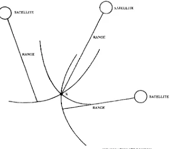
GPS navigation is based on the principle of satellite ranging. Satellite ranging involves measuring the time it takes the satellite signal to travel from the satellite to the navigation set. By dividing the travel time by the speed of light, the distance between the satellite and the navigation set is known. By ranging three satellites, a three-dimensional picture, such as the one shown in figure 1-12, can be developed. The distance measurement to each satellite results in a
sphere representing the distance from the navigation set to the satellite. The point where the three spheres intersect (X) is the position of the navigation set, This explanation does not account for errors. For satellite ranging to provide accurate position data, the following three sources of error must be compensated for:
Satellite position and clock error
Atmospheric delay of satellite signals
Navigation set clock error
With these errors compensated for, the GPS can determine position fixes within 50 feet or less and is accurate to within a tenth of a meter-per-second for velocity and 100 nanoseconds for time. This accuracy, however, requires inputs from four satellites.
USER EQUIPMENT
User equipment is installed in ships, aircraft, and motorized vehicles. The vehicle version can also be carried by personnel (particularly SEAL teams and other special forces units) as a manpack. The most common manpack version is the AN/PSN-8( ). The most common shipboard GPS receiver is the AN/WRN-6. These GPS receivers will be described later in this chapter.
Signal Acquisition
Figure 1-12.—Satellite ranging.
Navigation Set Clock Error
GPS navigation sets determine distance to a satellite by accurately measuring the time difference between satellite signal transmission and when the navigation set receives this signal. This difference in time is directly proportional to the distance between the satellite and the receiver. Therefore, the same time reference must be used by both the receiver and the satellite.
The clock in the GPS receiver in not nearly as accurate as the atomic clock in the satellite. This causes the receiver and satellite clocks to be slightly o u t o f s y n c , which in turn causes the time measurements to be inaccurate. The error is further compounded by the distance calculation, so the position of the navigation set cannot be accurately determined.
The navigation set compensates for these errors by using the distance measurement from a fourth satellite to calculate the clock error common to all four satellites. The navigation set then removes the clock error from the distance measurements, and then
determines the correct navigation set position.
Signal Delay and Multipath Reception
Two types of atmospheric delay can affect the accuracy of navigation set signal measurements. The first is tropospheric delay. Tropospheric delay can be accurately predicted; the prediction is included in the almanac data.
The second type of delay is caused when the satellite signal passes through the ionosphere. This type of signal delay is caused by the ionosphere being thicker in some areas and by satellite signals received from nearer the horizon having to pass through more of the ionosphere than those received from directly overhead. Ionospheric delay will phase shift the lower satellite transmission frequency, L2-RF, more than the higher frequency, L1-RF. The navigation set measures ionospheric delay by measuring the phase shift between these two signals and then uses this computation to compensate for the ionospheric delay.
reflected signals to reach the navigation set at different times than the original signal. The reception of multipath signals may cause errors in the navigation set calculations. The AN/WRN-6 navigation set makes operators aware of multipath errors by a “fail” or “warn” message and/or fluctuations in the carrier-to-noise ratio. Multipath reception may be corrected by changing the ship’s position.
AN/WRN-6(V) Satellite Signals Navigation Set
The Satellite Signals Navigation Set AN/WRN-6(V)computes accurate position coordinates, elevation, speed, and time information from signals transmitted by NAVSTAR Global Positioning System (GPS) satellites. In the P mode, it has an accuracy of 16 meters. In the C/A
C/A mode. it has an accuracy of 100 meters, though better results have been obtained by individual users.
The AN/WRN-6(V), shown in figure 1-13, operates in three modes.
The “Initialization” mode is part of the set start-up. During initialization, the operator tests current position, date, and time data, either manually or from other equipment. The data entered is used to speed up satellite acquisition.
[image:27.612.111.506.239.690.2]“Navigation” is the normal operating mode. During the navigation mode, the set receives satellite data, calculates
navigation data, exchanges data with other interconnected systems, and monitors the set’s performance. The navigation mode allows the operator to enter mission data; view position, velocity, and time data; and control the set’s configuration.
The “self-test’’ mode allows the operator to perform a complete test of the navigation set at any time. When the set is in “test,” it will not track satellites.
The two major components of the AN/WRN-6(V) are the R-2331/URN receiver and the indicator control C-11702/UR. The other units (antenna, antenna amplifier, and mounting base) perform functions similar to those of similar units in other systems. For more detailed
operation and maintenance technical manual.
AN/PSN-8( ) Manpack Navigation Set
[image:28.612.115.492.270.629.2]The AN/PSN-8( ) operates similarly to the AN/WRN-6(V), though obviously it is not interfaced with other equipment. Shown in figure 1-14, each manpack contains a receiver section and a computer section. The receiver processes the rf signals from the satellites and sends the satellite’s positions and times to the computer. The computer uses the positions and times to find the satellite set’s position coordinates, elevation, and changes in the position of the manpack set. The time it takes for the set to change position is used to compute speed. For more detailed information on this navigation set. refer to the information on this system, refer to the AN/WRN-6(V) operator’s manual for the AN/PSN-8( ) Manpack
Navigation S e t . T h e A N / V S N - 8 ( ) V e h i c u l a r Navigation Set is also included in this manual.
NAVIGATIONAL AIDS
Other equipment used for navigation that ETs are responsible for includes: navigation radars, surface search radars (sometimes used as navigation radars) and fathometers. Information on surface search and navigation radars is contained in NAVEDTA 12414,
Radar Systems.
The following paragraphs will discuss fathometers.
FATHOMETERS
Fathometers are used for taking depth soundings. They are particularly useful when the vessel is transitioning shallow, unfamiliar waters. A block diagram of the Sonar Sounding Set AN/UQN-4A is shown in figure 1-15,
[image:29.612.101.522.268.640.2]On many ships the Sonar Technicians will be responsible for this equipment, but there are ships (mostly noncombatants) on which ETs are responsible for the fathometers. For more detailed information on fathometers, refer to the appropriate equipment technical manual.
TACTICAL AIR
INTRODUCTION
Before we begin discussing TACAN, you need to recall the definition of the polar-coordinate system. The polar-coordinate system is a geometric system used to locate points on a plane. In electronics, it is usually used for plotting antenna directional patterns.
TACAN is a polar-coordinate type radio air-navigation system that provides an aircrew with distance information, from distance measuring e q u i p m e n t ( D M E ) , a n d b e a r i n g ( a z i m u t h ) information. This information, as shown in figure 2-1, is usually provided by two meters. One meter indicates, in nautical miles, the distance of the aircraft from the surface beacon. The other meter indicates the direction of flight, in degrees-of-bearing, to the geographic location of the surface beacon. By using the TACAN equipment installed in the aircraft and TACAN ground equipment installed aboard a particular surface ship or shore station, a pilot can obtain bearing to and distance from that location. He or she can then either:
(1) fly directly to that particular location, or
CHAPTER 2
[image:31.612.56.270.449.693.2]NAVIGATION (TACAN)
Figure 2-1.—TACAN aircraft indication.
(2) use the bearing and distance from a specific beacon to fix his or her geographic location.
TACAN PRINCIPLES
The distance measuring concept used in TACAN equipment is an outgrowth of radar-ranging techniques. Radar-ranging determines distance by measuring the round-trip travel time of pulsed rf energy. The return signal (echo) of the radiated energy depends on the natural reflection of the radio waves. However, TACAN beacon-transponders generate artificial replies instead of depending on natural reflection.
Now look at figure 2-2. The airborne equipment generates timed interrogation pulse pairs that the surface TACAN system receives and decodes. After a 50-µsec delay, the transponder responds with a reply. The airborne DME then converts the round-trip time to distance from the TACAN facility. The frequency and identification code provide the geographic location of the transmitting beacon.
TACAN PULSE PAIRS
TACAN transponders use twin-pulse decoders to pass only those pulse pairs with the proper spacing. The purpose of this twin-pulse technique is to increase the average power radiated and to reduce the possibility of false signal interference.
After the receiver decodes an interrogation, the encoder generates the necessary pulse pair required for the transponder’s reply. A TACAN pulse pair generated by airborne or ground equipment is shown in figure 2-3.
CONSTANT TRANSPONDER DUTY-CYCLE
In principle, reply to aircraft
pairs-per-Figure 2-2.—Distance measuring round-trip travel time.
[image:32.612.48.572.42.249.2]second, per airborne equipment, to supply the necessary distance data. However, the total pulse out put of the transmitter constantly varies, according to the number of interrogating aircraft. In addition, random noise may trigger the transmitter.
Figure 2-3.—TACAN pulse train.
F o r t h e t r a n s p o n d e r t o p r o v i d e a z i m u t h information, the average power supplied to the antenna must be relatively uniform over time. To accomplish this, the transponder is operated on the constant-duty-cycle principle.
In this method of operation, the receiver uses automatic gain and squitter (noise generated output) controls to maintain a constant pulse output to the
transmitter, as shown in figure 2-4. I f f e w interrogations are being received, the gain and squitter of the receiver increase and add noise-generated pulses to the pulse train. If more interrogating aircraft come into range, the gain and squitter decrease and reduce the number of noise-generated pulses.
The relationship between the gain and the number of pulses is such that only a 2-dBm change in sensitivity occurs between reception from 1 aircraft and those from 100 aircraft. An added advantage of using a constant duty cycle is that overall transmitter power drain remains constant.
BEACON-TRANSPONDER IDENTIFICATION CODE
[image:32.612.63.285.372.548.2]Figure 2-4.—Transponder output pulse train.
15-HZ-BEARING INFORMATION The rf energy from the TACAN transmitter is fed to the antenna central element, which has no The timing of the transmitted pulses supplies the directivity in the horizontal plane. Parasitic elements actual distance information to the aircraft. This leaves positioned a r o u n d t h e c e n t r a l e l e m e n t are amplitude modulation as another medium for the electronically rotated (switched on and off) at 15 transponder to convey other information to the revolutions per minute. (See the section below on the aircraft. The TACAN beacon-transponder modulates OE-273(V)/URN antenna group). The distance the strength of the pulse to convey bearing information between the central element and the parasitic elements by producing a specific directional-radiating pattern is selected to obtain a cardioid radiation pattern. To rotated around a vertical axis. This signal, when an aircraft at a specific location, the distance data properly referenced, indicates the aircraft’s direction pulses appear to contain a 15-Hz amplitude-modulated from the TACAN facility. This signal and distance signal because of the rotation of the cardioid radiation data give a two-piece fix (distance and direction) for pattern. This pattern is shown
determining specific aircraft location. and view B.
Figure 2-5.—TACAN radiation pattern: A. cardioid pattern; B. Ampltitude-modulated pulse pairs.
The aircraft TACAN equipment obtains bearing information by comparing the 15-Hz modulated signal with a 15-Hz reference burst signal it receives from the ground facility. The phase relationship between the 15-Hz modulated signal and the 15-Hz reference burst signal depends on the location of the aircraft in the cardioid pattern. The 15-Hz reference burst signals are transmitted when the maximum signal of the cardioid pattern aims due East. This group of 12 pulse pairs is commonly referred to as the North or main reference burst. You can see the relationship between the reference pulses and the cardioid pattern by comparing view A and view B of figure 2-5.
135-HZ BEARING INFORMATION
Errors arising from imperfections in
the phase
measuring circuits and radio propagation
effects are
known as site error. These errors are significantly reduced by the addition of 32 outer parasitic elements added to the electronically scanned antenna. (See the
section on the OE-273(V)/URN antenna group). Electronically switching these elements modifies the antenna cardioid pattern. Though the cardioid pattern is still predominant, it is altered by superimposed ripples. The aircraft now receives the 15-Hz signal with a 135-Hz ripple amplitude modulated on the distance data pulses (figure 2-6).
To furnish a suitable reference for measuring the phase of the 135-Hz component of the envelope wave, the transponder is designed to transmit a coded 135-Hz reference burst similar to that explained for the 15-Hz reference. The 135-Hz reference group is commonly referred to as the auxiliary or aux reference b u r s t .
The composite TACAN signal is composed of 2 7 0 0 i n t e r r o g a t i o n r e p l i e s a n d n o i s e p u l s e pairs-per-second, plus 180 North burst pulse second, 720 auxiliary burst pulse pairs-per-second, for a total of 3600 pulse pairs-per-pairs-per-second, or 7200 pulses-per-second.
TACAN SIGNAL PRIORITIES
Priorities have been established for transmission of the various types of TACAN signals. These priorities are as 1. 2. 3. 4. follows:
Reference bursts (North and auxiliary)
Identification group
Replies to interrogations
Squitter
Therefore, the identification group, replies, or squitter will be momentarily interrupted for the transmission of either the main or auxiliary reference group. The transmission of replies or squitter will be interrupted every 37.5 seconds during the transmission of an identification code dot or dash.
CHARACTERISTICS OF RADIO BEACON SIGNALS
Figure 2-6.—TACAN modulation envelope
spacing are a characteristic of that particular TACAN signal element. However, it is important to understand that proper spacing between pulses and pulse pairs is what actually provides the aircraft with the means to distinguish between the TACAN pulses and any other pulses that might be present on the received radio frequency. Check the reference data in the appropriate technical manual for specific pulse characteristics and spacing.
TACAN EQUIPMENT
Many different types of TACAN equipment have been used for air navigation. Today, the AN/URN-25 is taking over the task of tactical air navigation from the older AN/URN-20 on new construction ships and as ships complete overhaul. Two types of antennas are used with the AN/URN-25. They are the OE-273(V)/URN, used primarily in shipboard installations, and the OE-258/URN, which is used primarily ashore. Because both antenna systems are similar in theory of
operation, we will discuss only the OE-273/URN. In the following paragraphs, we will discuss the AN/URN-25 and the antenna group 0E-273(V)/URN, and then we will briefly discuss the AN/URN-20.
TACAN SET AN/URN-25
The AN/URN-25 TACAN is used as a ground-based or shipborne beacon transponder to provide range and bearing information to aircraft equipped with TACAN equipment. It consists of two major units: the Transponder Group OX-52/URN-25, commonly referred to as unit 1, and the Control-Indicator C-10363/URN-25, commonly referred to as unit 2. These units are shown in figure 2-7. Each transponder is housed in a cabinet with two vertical drawers, one containing a coder keyer and the other containing a receiver-transmitter.
It may be mounted in its own cabinet or in a standard 19-inch rack.
To increase the channels available, the TACAN set can be operated in either the X or Y mode. The Y mode changes the pulse pair spacing and the auxiliary burst count and spacing, and increases system delay.
ANTENNA GROUP OE-273(V)/URN
Shown in figure 2-8, the Antenna Group OE-2 7 3 / U R N i s a s o l i d - s t a t e , h i g h - p e r f o r m a n c e , electronically-scanned, all-band TACAN antenna system, complete with integral monitoring system and built-in fault isolation capability. The antenna group develops the coarse and fine bearing modulations electronically.
Rather than forming the TACAN radiation pattern by the old mechanical rotation method, the AS-3240 achieves the same effect by digital switching of
parasitic elements arranged in concentric arrays around the central radiator. Twelve inner elements provide the 15-Hz modulation (replacing the single-phase rotating parasitic element in the mechanically rotated antenna), and 32 outer elements provide the 135-Hz modulation (replacing the nine outer elements of the rotated antenna). The 15- and 135-Hz modulation pattern is provided by electronically switching the diodes in each of the parasitic elements in prescribed time sequence, which is repeated once in each 15-Hz interval.
[image:37.612.80.529.359.690.2]In effect, the elements are rotated electrically, rather than mechanically. An advantage this provides is the elimination of the bandwidth limitations inherent in the old mechanically-rotated antennas. In the electronically-scanned antenna, the appropriate ring for a given frequency segment is activated by a fast electronic switch, based on information from the T A C A N f r e q u e n c y s y n t h e s i z e r . T h i s a l l o w s instantaneous band switching and all-band operation.
TACAN SET AN/URN-20
Though not modern by any standard, the AN/URN-20 TACAN set is reliable and operates similarly to the AN/URN-25. Shown in figure 2-9, it uses the same electronically-scanned antenna and control-indicator as the 25. The AN/URN-20 is being replaced by the AN/URN-25.
CAPABILITIES AND LIMITATIONS
In the X mode of operation, the TACAN set transmits on one of 126 discrete channel frequencies (which are 1-MHz apart) from 962 to 1024 MHz and from 1151 to 1213 MHz. In the Y mode of operation, the set transmits on one of 126 discrete channel frequencies (which are 1-MHz apart) within the range of 1025 to 1150 MHz. The navigation set receiver, operating in the 1025- to 1150-MHz range for both the X and Y modes, is always displaced 63 MHz from the transmitter frequency.
The TACAN set can simultaneously provide individual distance measuring service for up to 100 interrogating aircraft. O f t h e 3 , 6 0 0 p u l s e pairs-per-second transmitted by the TACAN, 900 pulse pairs (MAIN and AUXILIARY bursts) contain the bearing information; the remaining 2,700 pulse pairs are either random noise pulses, identity pulses, or replies to interrogating aircraft. Once every 30 seconds, the interrogation replies and random noise pulses are interrupted for the transmission of identity pulses.
APPENDIX I
LIST OF ACRONYMS
AUX- auxiliary.
BITE- built-in test equipment.
C/A CODE- course acquisition code.
DB- decibel.
DBM- decibel with a reference zero value of 1 mW.
DME- distance measuring equipment.
DOD- Department of Defense.
DR- dead reckon.
EW- electronic warfare.
FRP- Federal Radio Navigation Plan.
GMT- Greenwich Mean Time.
HZ- Hertz.
KHZ-- kilohertz.
LOP- line-of-position.
LORAN- Long Range Aid to Navigation.
LOS- line-of-sight.
MHZ-- megahertz.
MS- millisecond.
MW-- milliwatt.
NAV-MSG- NAVIGATION-message.
NAVSAT- navigation satellite.
NAVSTAR GPS- satellite Global Positioning
System.
NNSS- Navy Navigation Satellite System.
NTDS- Naval Tactical Data System.
OMEGA- VLF radio navigation.
P CODE- precise code.
PPS- pulses per second.
PROM- programmable read-only memory
RF- radio frequency.
SATNAV-- satellite navigation
S/D- synchro to digital.
SINS- Ship’s Inertial Navigation System.
TACAN- Tactical Air Navigation.
TCA- time of closest approach.
UT-- Universal Time.
VOR- VHF--omnidirectional range.
APPENDIX II
REFERENCES USED TO DEVELOP THE TRAMAN
NOTE: Although the following references were current when this
TRAMAN was published, their continued currency cannot be assured. You, therefore, need to ensure that you are studying the latest revision.
Electronics Technician 3 & 2, NAVEDTRA 10197, Naval Education and
Training Programs Management Support Activity, Pensacola, FL, 1987.
Inertial Navigation Set AN/WSN-5, NTP S-30-7519E, Naval Sea Systems
Command, Washington, DC, 1991.
Manpack Navigation Set AN/PSN-8( ), Operator’s Manual
EE170-AA-OPI-010/MV, Space and Naval Warfare Systems Command, Washington, DC, 1990.
Naval Aeronautical Facilities, Naval Shore Electronics Criteria, NAVELEX
0101,107, Naval Electronic System Command, Washington, DC, 1971.
NAVSTAR Global Positioning System (GPS) User Equipment, NTP E-70-8215E,
Space and Naval Warfare Systems Command, Washington, DC, 1993.
Satellite Signals Navigation Set AN/WRN-6(V), Technical Manual
EE-170-AA-OMI-010/WRN6, Space and Naval Warfare Systems Command, Washington, DC, 1990.
Shipboard Electronics Material Officer, NAVEDTRA 12969, Naval Education
and Training Programs Management Support Activity, Pensacola, FL, 1992
TACAN, Navigation Set AN/URN-25, Technical Manual EE172-AB-OMI-010,
INDEX
D
Doppler principles
refraction measurement, 1-8 velocity computation, 1-8
G
O
NNSS
computer center, 1-7 injection station, 1-7 naval observatory, 1-7 satellites, 1-6
tracking stations, 1-7
GPS navigation sets
AN/PSN-8 manpack, 1-18 AN/WRN-6, 1-17 L LORAN line-of-position, 1-2 N Navigation aids fathometers, 1-19 radar, 1-19 Navigation fundamentals dead reckoning, 1-1 electronic navigation, 1-2 piloting, 1-2
tactical, 1-1
Navigation sets
AN/SRN-19, 1-11 AN/WRN-5, 1-9
NAVSTAR Global Positioning System clock error, 1-16
ground control, 1-14 ionospheric delay, 1-16 multipath reception, 1-16 satellite ranging, 1-15
satellite signal structure, 1-15 satellites, 1-14
signal acquisition, 1-15 tropospheric delay, 1-16
Omega
hyperbolic navigation, 1-3
s
SINS accelerometers, 1-4 advantages, 1-3 AN/WSN-5, 1-5 gyros, 1-4servo systems, 1-4
T
T A C A N
aircraft indications, 2-1 aux reference burst, 2-4
bearing information (15 Hz), 2-3 bearing information (135 Hz), 2-4 cardioid, 2-3
constant transponder duty-cycle, 2-1 identification code, 2-2
north reference burst, 2-4 principles, 2-1
pulse pairs, 2-1 signal priorities, 2-4 squitter, 2-2
TACAN equipment
antenna group OE-273(V)/URN, 2-7 AN/URN-20, 2-9
Assignment Questions
Information: The text pages that you are to study are
ASSIGNMENT 1
Textbook Assignment: “Surface Navigation Systems,” chapter 1, pages 1-1 through 1-19; and
“Tactical Air Navigation,” chapter 2, pages 2-1 through 2-9.
1-1.
1–2.
1–3.
1–4.
1-5.
Tactical navigation is directly concerned with maneuvering the ship in navigable waters.
1. True
2. False
Estimating ship’s position between known navigational points or fixes is known as
1. ship maneuvering
2. dead reckoning
3. ship reckoning
4. dead maneuvering
Radio navigation consists of which of the following categories?
1. Sub-space systems
2. Space–based systems
3. Terrestrial systems
4. Both 2 and 3 above
One of the characteristics of dead reckoning is that the accuracy of the estimated position never
exceeds the navigation method used
to obtain the last fix. What
happens to the accuracy of the estimated position over time?
1. It increases
2. It decreases
3. It stays the same
4. It fluctuates
Referring to landmarks with known positions on earth describes which one of the following navigation methods?
1. Celestial
2. Charting
3. Dead reckoning
4. Piloting 1-6. 1-7. 1-8. 1–9. 1-10.
Which of the following actions required to determine position in piloting is/are not required in electronic navigation?
1. Seeing the landmarks
2. Determining the ship’s heading
3. Having the ship on a dead
reckoned course
4. Both 2 and 3 above
According to the 1992 Federal Radio Navigation Plan, which of the
following systems will become the primary reference navigation system for surface ships?
1. LORAN
2. OMEGA
3. NAVSTAR
4. TACAN
LORAN takes advantage of what radio signal characteristic?
1. Constant amplitude
2. Constant velocity
3. Constant phase
4. Constant volume
OMEGA is a hyperbolic phase— difference measuring system that compares the phase angle of two or more radio signals synchronized to what device or factor?
1. A common receiver
2. A common signal shift
3. A common time base
4. A common transmitter
Which navigation system continually computes the latitude and longitude of a ship by sensing acceleration?
1. NAVSTAR
2. OMEGA
3. MILSTAR