ISSN Print: 2327-588X
A Novel Topology of Single-Phase AC-DC
Integrated Boost-SEPIC (IBS) Converter Using
Common Part Sharing Method (CPSM) for High
Step-Up Applications
Mohammad Bazlur Rashid, Mohammad Abdul Moin Oninda, Fahim Faisal,
Mirza Muntasir Nishat, Golam Sarowar, Md. Ashraful Hoque
Department of Electrical and Electronic Engineering, Islamic University of Technology, Gazipur, Bangladesh
Abstract
A novel topology of Integrated Boost-SEPIC (IBS) AC-DC converter using common part sharing method (CPSM) has been proposed in this paper. Con-ventional boost converters with bridge rectifier configuration are inefficient due to limited voltage step-up ratio which may not be applicable for high step-up applications as in the case of micro generators. The proposed IBS to-pology is based on the common part sharing method capable of operating both for positive and negative half cycle of the input signal. Result and simu-lation were conducted using PSIM environment. The proposed AC-DC IBS topology eliminates the requirement of bridge rectifier achieving high effi-ciency (about 99%), improved power factor (0.75, leading) and lower THD (about 38.8%) which is within IEEE standard.
Keywords
Integrated Boost-SEPIC (IBS), Bridgeless AC-DC Converter, Voltage Gain, THD Minimization, Efficiency Improvement, Power Factor Correction
1. Introduction
Continuous advancement in power electronics has led to the development of self-powered devices requiring low power, mainly analog and digital circuits. Self-powered devices harvest the ambient energies from micro generators and can perform their operation without the requirement of continuous external power supply [1] [2] [3]. The output of micro generators is AC having a low How to cite this paper: Rashid, M.B.,
Oninda, M.A.M., Faisal, F., Nishat, M.M., Sarowar, G. and Hoque, M.A. (2018) A Novel Topology of Single-Phase AC-DC Integrated Boost-SEPIC (IBS) Converter Using Common Part Sharing Method (CPSM) for High Step-Up Applications. Journal of Power and Energy Engineering, 6, 38-47.
https://doi.org/10.4236/jpee.2018.66003
Received: May 11, 2018 Accepted: June 25, 2018 Published: June 28, 2018
Copyright © 2018 by authors and Scientific Research Publishing Inc. This work is licensed under the Creative Commons Attribution International License (CC BY 4.0).
http://creativecommons.org/licenses/by/4.0/ Open Access
mitigate the problems associated with high voltage output, various types of step-up converters, utilizing the voltage conversion ability have been proposed achieving high performance [12]-[20]. Conventional power converters for ener-gy conversion, mostly consist of two stages: a diode bridge rectifier for AC-DC conversion followed by a standard Buck or Boost DC-DC converter [21] [22] [23][24]. However, there are major disadvantages in using the two-stage power converters to condition the outputs of the electromagnetic micro generators. Firstly, rectification is not feasible by the use of conventional diodes for very low voltage electromagnetic micro generators. Secondly, even if the diode bridge rec-tification is feasible, the forward voltage drops in the diodes will cause a large amount of losses and make the power conversion very inefficient. Moreover, bridge rectifier configuration of AC-DC converter suffers from distorted input current at low power factor. Therefore, several techniques have been developed and proposed to solve the harmonic distortions in the input current as well as to improve the power factor [25][26][27].
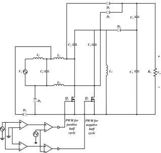
In this paper, a novel topology of Integrated Boost-SEPIC (IBS) converter has been proposed which combines the Boost converter with an isolated SEPIC converter as a series output module in order to obtain high step-up ratio and to overcome the above mentioned drawbacks. A common part sharing method (CPSM) as shown in Figure 1, avoiding bridge rectification configuration, has been presented to amplify the output voltage.
The proposed circuit along with principle of operation has been illustrated in Section 2. Section 3 deals with the steady state analysis of the proposed conver-ter. Result and simulation verifying the feasibility of the proposed converter has been discussed in Section 4. The proposed converter is therefore able to achieve high step-up ratio along with improved efficiency, power factor and minimized THD.
2. Proposed Circuit Configuration and Operation
The proposed topology as shown in Figure 2 comprises of a switched mode In-tegrated Boost-SEPIC (IBS) AC-DC converter based on the principle of CPSM. The proposed topology consists of four inductors (Lf, L1-L3), five capacitors (Cf,
Figure 1. Common part sharing between boost and SEPIC conver-ter.
Figure 2. Proposed integrated Boost-SEPIC (IBS) converter.
C1-C4), five diodes (D1-D5) and two switches (Q1and Q2).
Under the proposed converter, a sub-circuit has been proposed, providing the gating signal to the switches (Q1 and Q2). The proposed AC-DC converter can
operate on both positive and negative half cycle of the input signal. Switch, Q2
remains off throughout the positive half cycle of the input voltage and the switch Q1 remains off throughout the negative half cycle of the input signal. In the positive
[image:3.595.217.536.298.601.2]In the boost portion of the circuit,
(
01)
0s on s off
V t + V V t− =
where, ton = on time, toff = off time, Vs = supply voltage and V01 = output voltage
of Boost converter.
01 0
s on s off off
V t +V t −V t =
(
)
01s on off off
V t +t =V t
01 off s on off t V
V =t +t
01 1 1 s
V V
D
=
− (1)
where, D = duty cycle.
In the SEPIC portion of the circuit,
02 1 1 s V V D = −
where, V02 = output voltage of SEPIC converter.
(
)
02 1 s
V −D =DV
(
)
02 1DVs V
D
=
− (2)
The overall output voltage of the integrated Boost-SEPIC converter, combin-ing Equations (1) and (2),
01 02 o
V V= +V
1
1 1
o s D s
V V V
D D
= +
− −
1
1 1
o D s
V V D D = + − − 1 1
o D s
V V
D
+
= − (3)
So, the voltage gain, G
(a) (b)
[image:5.595.59.540.58.461.2](c) (d)
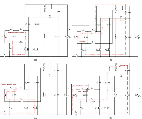
Figure 3. Principle of operation of IBS converter. (a) Mode 1: Positive half cycle when switch Q1 is on and Q2 is off, (b) Mode 2: Positive half cycle when switch Q1 is off and Q2 is off, (c) Mode 3: Negative half cycle when switch Q1 is off and Q2 is on and (d) Mode 4: Negative half cycle when switch Q1 is off and Q2 is off.
1 1
D G
D
+ =
−
From the above equations it is observed that the output voltage is 1
1
D D
+ −
times the input voltage, which is significantly high.
4. Result and Analysis
The proposed circuit has been designed and implemented using PSIM 9.1 envi-ronment. The parameters of the proposed circuit used for simulation is given in Table 1. The proposed IBS topology has been compared with conventional sin-gle-phase AC-DC diode-bridge Boost rectifier conversion circuit.
The gate driving circuit as shown in Figure 4 generates PWM signal for the switches Q1 and Q2. The gating sequence for activating different switches has
Load (RL) 100 Ω
Figure 4. Gate Driving circuit of the proposed IBS
converter.
been shown in Figure 5.
Typical input voltage and current waveform is shown in Figure 6(a) and output voltage, current and power is shown in Figure 6(b) and Figure 6(c).
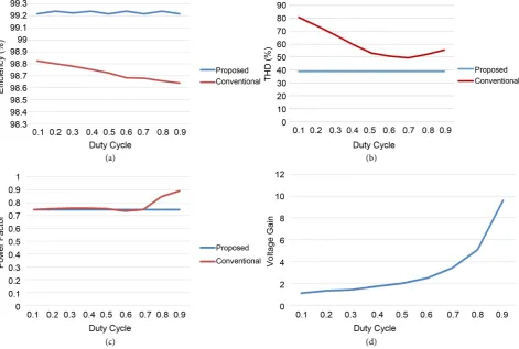
For performance comparison among the proposed and conventional schemes, results are evaluated in terms of THD (%) of input current, input power factor and efficiency (%) of conversion. The outcomes of the discussion are discussed below as shown in Figure 7.
In terms of efficiency, the proposed IBS converter as shown in Figure 7(a) exhibits high efficiency (about 99%) over the whole range of duty cycle com-pared to the conventional converter. The proposed IBS converter exhibits lower input current THD and high input power factor throughout all the duty cycles compared to conventional schemes as shown in Figure 7(b) and Figure 7(c). In addition, with the increment of duty cycle, the output voltage also increases sig-nificantly. The voltage gain, G with respect to duty cycle, D was plotted as shown in Figure 7(d) which is coherent with the output voltage Equation (3).
5. Conclusion
A novel topology of integrated Boost-SEPIC (IBS) converter for high step-up and high performance applications has been proposed combining the Boost converter and an isolated SEPIC converter using common part-sharing method (CPSM). The proposed converter achieves high step-up ratio with additional
Figure 5. PWM signal generated by the proposed gate driving circuit for the IBS converter.
(a)
(b)
(c)
Figure 6. Input voltage and current waveforms for the proposed IBS converter. (b) Output voltage,
current and power waveforms of the proposed IBS converter using output capacitor of 220 uF (c) Out-put voltage, current and power waveforms of the proposed IBS converter using an outOut-put bulk capaci-tor of 1000 uF.
Figure 7. Comparison between proposed IBS converter and conventional AC-DC Boost converter. (a) Percentage efficiency, (b)
percentage of Total Harmonic Distortion (THD), (c) Power Factor (PF) and (d) Voltage Gain of the proposed converter.
[image:8.595.63.535.378.695.2]step-up ability of the isolated SEPIC converter, while at the same time main-taining the continuous input current characteristics of the Boost converter. Moreover, the proposed IBS converter exhibited improved performance in case of efficiency (99%), THD (38.8%) and maintained a leading power factor (0.75). In order to have better performance, close loop implementation of the proposed converter can be conducted to obtain better power factor by employing suitable power factor correction techniques.
References
[1] Dwari, S. and Parsa, L. (2010) An Efficient AC–DC Step-Up Converter for Low-Voltage Energy Harvesting. IEEE Transactions on Power Electronics, 25, 2188-2199. https://doi.org/10.1109/TPEL.2010.2044192
[2] Dwari, S., Dayal, R. and Parsa, L. (2008) A Novel Direct AC/DC Converter for Effi-cient Low Voltage Energy Harvesting. 34th Annual Conference of IEEE Industrial Electronics, Orlando, FL, 10-13 November 2008, 484-488.
https://doi.org/10.1109/IECON.2008.4758001
[3] Mohan, N., Undeland, T.M. and Robbins, W.P. (1995) Power Electronics: Conver-ters, Applications and Design. 2nd Edition, John Wiley & Sons Inc., New York, 172-178.
[4] Ang, S.S. (1995) Power Switching Converters. Marcel Dekker, Inc., New York, 27-37.
[5] Erickson, R.W. and Masksimovic, D. (1950) Fundamentals of Power Electronics. 2nd Edition, John Wiley, New York, 39-55.
[6] Williams, C.B. and Yates, R.B. (1995) Analysis of a Micro-Electric Generator for Microsystems. Proceedings of the International Solid-State Sensors and Actuators Conference, Stockholm, 25-29 June 1995, 369-372.
[7] Mitcheson, P.D., Green, T.C., Yeatman, E.M. and Holmes, A.S. (2004) Architectures for Vibration-Driven Micropower Generators. Journal of Microelectromechanical Systems, 13, 429-440. https://doi.org/10.1109/JMEMS.2004.830151
[8] Tseng, C.-J. and Chen, C.-L. (1998) A Passive Lossless Snubber Cell for Nonisolated PWM DC/DC Converters. IEEE Transactions on Industrial Electronics, 45, 593-601. https://doi.org/10.1109/41.704887
[9] Smith, K.M. and Smedley, K.M. (1999) Properties and Synthesis of Passive Lossless Soft-Switching PWM Converters. IEEE Transactions on Power Electronics, 14, 890-899. https://doi.org/10.1109/63.788486
[10] Jovanovic, M.M. (1998) A Technique for Reducing Rectifier Reverse-Recovery-Related Losses in High-Power Boost Converters. IEEE Transactions on Power Electronics, 13, 932-941. https://doi.org/10.1109/63.712314
[11] Levy, H., Zafrany, I., Ivensky, G. and Ben-Yaakov, S. (1997) Analysis and Evaluation of a Lossless Turn-On Snubber. Proceedings of APEC 97—Applied Power Elec-tronics Conference, Atlanta, GA, 27-27 February 1997, 757-763 Vol. 2.
https://doi.org/10.1109/APEC.1997.575729
[12] Nakamura, M., Ogura, K. and Nakaoka, M. (2004) Soft-Switching PWM Boost Chopper-Fed DC-DC Power Converter with Load Side Auxiliary Passive Resonant Snubber. Journal of Power Electronics, 4, 161-168.
[13] Cho, J.-G., Jeong, C.-Y., Lee, H.-S. and Rim, G.-H. (1998) Novel Zero-Voltage- Transition Current-Fed Full-Bridge PWM Converter for Single-Stage Power Factor
with High Step-Up Voltage Gain. IEEE Transactions on Industrial Electronics, 56, 3144-3152. https://doi.org/10.1109/TIE.2009.2022512
[17] Wai, R.J. and Duan, R.Y. (2005) High-Efficiency DC/DC Converter with High Vol-tage Gain. IEE Proceedings-Electric Power Applications, 152, 793-802.
https://doi.org/10.1049/ip-epa:20045067
[18] Vanitha, R. and Geetha, V. (2017) A High Step up Voltage Gain of Boost Converter with Switched Capacitor Technique Using FLC for Renewable Energy System. 2017
International Conference on Computation of Power, Energy Information and Commuincation (ICCPEIC), Melmaruvathur, India, 22-23 March 2017, 645-649. [19] Park, K.-B., Seong, H.-W., Kim, H.-S., Moon, G.-W. and Youn, M.-J. (2008)
Inte-grated Boost-Sepic Converter for High Step-Up Applications. 2008 IEEE Power Electronics Specialists Conference, Rhodes, 15-19 June 2008, 944-950.
https://doi.org/10.1109/PESC.2008.4592051
[20] Mamun, M.A., Sarowar, G., Hoque, M.A. and Rahman, A.A.M. (2017) A Novel Non Isolated DC-DC Step up Converter for Photovoltaic Systems. 20174th International Conference on Advances in Electrical Engineering (ICAEE), Dhaka, 28-30 Septem-ber 2017, 330-335. https://doi.org/10.1109/ICAEE.2017.8255376
[21] Pressman, A.I. (1998) Switchmode Power Supply Handbook. 2nd Edition, McGraw-Hill, New York.
[22] Mohan, N., Undeland, T.M. and Robbins, W.P. (2003) Power Electronics. Conver-ters, Applications and Design. John Wiley and Sons, Inc.
[23] Brown, M., Kularatna, N., Mack, R.A. and Maniktala, S. (2007) Power Sources and Supplies: World Class Designs. Newnes Press, Oxford, UK.
[24] Kazimierczuk, M.K. (2008) Pulse-Width Modulated DC-DC Power Converters. Wiley, New York. https://doi.org/10.1002/9780470694640
[25] Oninda, M.A.M., Sarowar, G. and Galib, M.M.H. (2017) Single-Phase Switched Ca-pacitor AC-DC Step down Converters for Improved Power Quality. 2017 IEEE Re-gion 10 Humanitarian Technology Conference (R10-HTC), Dhaka, Bangladesh, 21-23 December 2017, 520-523.
[26] Singh, B., Singh, S., Chandra, A. and Al-Haddad, K. (2011) Comprehensive Study of Single-Phase AC-DC Power Factor Corrected Converters with High-Frequency Isolation. IEEE Transactions on Industrial Informatics, 7, 540-556.
https://doi.org/10.1109/TII.2011.2166798
[27] Schlecht, M.F. and Miwa, B.A. (1987) Active Power Factor Correction for Switching Power Supplies. IEEE Transactions on Power Electronics, PE-2, 273-281.
https://doi.org/10.1109/TPEL.1987.4307862