Appendix A
ASME – J. Computing & Inforomation Science in Engineering
Paper - 2014
Kaufman – JCISE -14 - 1238 Page 1 Copyright © 2014 by ASME
ESDA1014 - 20304 June 25-27, 2014, Copenhagen, Denmark
Reverse Engineering using Close Range Photogrammetry for Additive Manufactured
Reproduction of Egyptian Artefacts and other O
bjets d'art.
John Kaufman
Lancaster University, Lancashire, UK
Allan EW Rennie
Lancaster University, Lancashire, UK
Morag Clement
Kendal Museum, Kendal, Cumbria, UK
ABSTRACT
Photogrammetry has been in use for over one hundred and fifty years. This research considers how digital image capture using a medium range Nikon Digital SLR camera, can be transformed into 3D virtual spatial images, and together with additive manufacturing (AM) technology, geometric representations of the original artefact can be fabricated. The research has focused on the use of photogrammetry as opposed to laser scanning (LS), investigating the shift from LS use to a Digital Single Lens Reflex (DSLR) camera exclusively.
The basic photogrammetry equipment required is discussed, with the main objective being simplicity of execution for eventual realisation of physical products. As the processing power of computers has increased and become widely available, at affordable prices, software programs have improved, so it is now possible to digitally combine multi-view photographs, taken from 360°, into 3D virtual representational images. This has now led to the possibility of 3D images being created without LS intervention.
Two methods of digital data capture are employed and discussed, in acquiring up to 130 digital data images, taken from different angles using the DSLR camera together with the specific operating conditions in which to photograph the objects. Three case studies are documented, the first, a modern clay sculpture, whilst the other two are 3000 year old Egyptian clay artefacts and the objects were recreated using AM technology. It has been shown that with the use of a standard DSLR camera and computer software, 2D images can be converted into 3D virtual video replicas as well as solid, geometric representation of the originals.
KEYWORDS: photogrammetry; reverse engineering; additive manufacturing; 123D Catch; PhotoScan; Studio Pro4.
INTRODUCTION
In 1860 Lenticular invented the Stereoscope, a device through which a 2D picture or photograph could be viewed as a 3D image. Thus the idea of using photographs to create 3D images is not new. Since the invention of the first digital camera in 1975 by Sasson, an engineer working for Eastman Kodak® [1], these cameras have developed from the 0.01 pixel of the first camera to 80+ megapixels at the top end of today’s professional range. The notion of stitching digital images together has become a reality. Since the late 1990’s obtaining digital images from laser scanners (LS) has become the predominant non-invasive method of 3D replication of both large and small buildings as well as objects and artefacts [2]. From the mid 1970’s techniques have evolved to stitch images to produce photo-mosaics [3, 4] and by the late 1990’s commercial computer programs such as Adobe’s
Photoshop Elements® [5] were widely available, being able to stitch full colour [3] 2D digital captured photographs together, creating panoramic views of city, sea or landscapes [6]. However, within the last few years, software has become available capable of stitching 70 or more high resolution digital images together to form a virtual 3D representation.
Photogrammetry has been defined by the American Society for Photogrammetry and Remote Sensing (ASPRS) as:
“the art, science, and technology of obtaining reliable information about physical objects and the environment through processes of recording, measuring and interpreting photographic images and patterns of recorded radiant electromagnetic energy and other phenomena”
[7].
Kaufman – JCISE -14 - 1238 Page 2 Copyright © 2014 by ASME created, and are then converted by additional software
programs such as Netfabb’sStudio Pro4® [10] to the files needed for additive manufacturing (AM) machines to replicate the photographed item and produce geometric representational models. The use of this technique could contribute to the reproduction, restoration or repair of damaged or broken antiquities by non-invasive methods at modest cost and by lay persons, who are computer literate but not necessarily expert in the use of specialised software or complex laser based scanning technologies.
Barsantia et al [11] investigated the different techniques and characteristics of both photogrammetry and LS, but the advantage of photogrammetry is that expensive LS equipment is not used and experienced technicians are no longer required to operate this equipment, since by using a relatively modest DSLR camera, 3D virtual images are obtainable.
MOTIVATION and RAISON D’ETRE of RESEARCH
There are 40 software programs claiming to be able to convert 2D digital photographs into 3D virtual images [12]. Several commercial computer software programs are available with a proven and reliable record to “stitch” multi-view photographs together to produce a 3D image. The primary research task investigates how well these software programs convert the digital 2D image into 3D CAD models and ultimately physical AM enabled models, and the results obtained are compared with the original photographed object.
There has been a trend of “hands on” exhibits in museums over the last few years, in order that all members of the public might more readily engage with the collections normally housed behind glass cabinets [13]. To fulfill this need, institutions such as Kendal Museum are interested in exploring potential opportunities from emerging technologies so as to replicate artefacts within their collection, in line with their mission statement:
“To safeguard and enhance all of the collections for the benefit of all Museum users, improve the visitor experience, to increase learning opportunities and ensure that the Museum has a sustainable future”.
The Kendal collection was established in 1796, as a ‘Cabinet of Curiosities’ While the museum’s value is in its collection of original objects, replicas of specific objects have their place. Due to the delicate nature of most objects, they are unable to be handled by the public. Replicas are very useful for handling sessions, especially for school sessions and loan boxes. Loan boxes are often used by rural schools where it is difficult to arrange actual visits to
the museum. The school can hire a box of material for a term and undertake practical activities on the school premises using museum resources.
Loan boxes and handling collections often comprise of un-accessioned objects (not in the main museum collection), or if there are large amounts of the same type of material some original material can be used. The loan boxes contain original Medieval and Roman material, but in the case of Egyptian collections it is rare to have an original handling collection. At present the Egyptian schools’ loan box is made up of general replicas (not items in the collection), and photocopies of documents and photos. Being able to replicate actual museum collection objects would be of great benefit to teaching in local schools about the Egyptians and the material held in the collection. Replicas, if exact, give the handler a chance to experience the size, texture and weight of objects if they are not able to handle the original object directly.
The relatively cheaper and simpler use of a DSLR camera, at the end of 2013 costing under £400.00, is a great attraction, as with a little training the museum’s own staff will be able to replicate many of their artefacts.
Fig.1 Clay Vase Fig.2 Sobekhotep
Kaufman – JCISE -14 - 1238 Page 3 Copyright © 2014 by ASME
Fig. 3 Fig. 4
Textured High Resolution Point Cloud Data Images
Figures 1 and 2 are photographs of the actual objects whilst Fig. 3 and 4 are screen shots of the textured high resolution point cloud data images created using Agisoft’s PhotoScan Pro®, as described in the next section. Photogrammetry can be used as a non-invasive method of image capture for AM geometric representation of objets d'art, limited only by the size of the AM machine, but in some cases, if the original model is too big for an AM machine, the CAD models can be sectioned and joined after physical fabrication.
DATA CAPTURE PROCESS
One of the main objectives of the research is concentrating on the ease of reproducing artefacts without complex hardware or software. A mid-range Nikon D3100® [14] DSLR camera was used, the digital data obtained being in *.jpg format. A standard fixed focus prime 50mm lens, which has a wide f1.4 or f1.8 aperture and minimum lens distortion and very good depth of field was considered, but a Nikon 18/55mm DX® auto focus lens was chosen, being directly compatible with the camera and able to automatically refocus around the subject from the many positions and angles encountered. Minimum lens distortion is achieved by keeping to the higher focal length end of 35/55mm on the lens. The disadvantage of this lens as opposed to a fixed lens is that the depth of field is not as good and slower shutter speeds are required as the aperture is not as wide. A resolution of 3456 x 2304 pixels equates to just under 8 megapixels.
The method of lighting and camera positioning for the artefacts were different in each case study, the common factor being that shadowless, flat lighting was required to illuminate all the artefacts as any shadow distorted the image captured and processed by the software. The same was true for any highlights or reflections that the lighting might have caused.
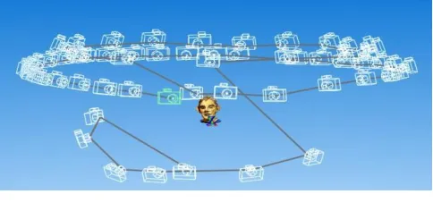
Fig.5 Multi Camera positions around Clay Head
The first study, a small modern clay head sculpture, has been included to show a comparative method in both AM printing and data capture. This is a semi glazed painted head measuring 105mm x 95mm, was placed in the centre of a room on a pedestal whilst the camera was moved in a full circle around the object and a digital image captured every 20o. A second and third circle of data images, at a higher and lower elevation of 20o to 30o to the horizontal, was obtained, ensuring that every part of the head was recorded and that a good overlap of images was obtained (Fig.5). The head is seen, arrowed, in the center of Fig. 6.
In addition to the natural daylight, which was softened by translucent window blinds, so as to cut out any glare, two overhead recessed ceiling fluorescent lights, each containing 36watt mini tubes plus two bip®
fluorescent floodlight units on telescopic stands were used. Each of these had three separate switched 100watt bulbs and white defusing front covers to balance the strong daylight, (Fig.6). It can be seen in Fig.6, that all reflective surfaces in the room were covered. Each tube was “Cool White” equating to Kelvin scale 4000K, whilst the floodlights equated to 5000K. This small difference in colour temperature, known as White Balance in camera terms, was automatically adjusted by the D3100 camera
“as digital cameras have a far greater capacity to compensate for the varying colours of light” [15]. Two smaller additional lights were used when a Light Tent was used, these having 100 watt, 5000K fluorescent bulbs.
Fig. 6 Indoor Open Room setup
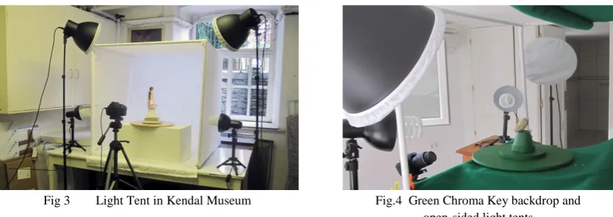
[image:4.612.321.563.70.188.2]Kaufman – JCISE -14 - 1238 Page 4 Copyright © 2014 by ASME specifically for this purpose, from 20mm plastic tubing
and suitable angle corners to make a metre square enclosure, covered in white poplin fabric with a front opening. So as to obtain strong contrast between the subject matter that was being photographed, interchangeable Chroma Key [16] backdrops were used, either white or green, depending on the colour of the subject, this contrast can be seen in Fig.2. As seen in Fig.7, the lights were placed outside the tent allowing the fabric to soften the lighting and disperse any shadows.
Fig.7 Light Tent set up in Museum workshop
The artefacts were placed upon a revolving turntable as the camera was static in the horizontal plane, only moving up and down by approx. 30o in the vertical plane to capture all faces of the artefacts. Depending on the complexity of the artefact the turntable was revolved either 15o, or for complex or detailed objects, 10o at a time per exposure, resulting in up to 130 or more digital images.
Of the three case studies discussed in this paper, the first is of the digital data capture of a clay head, which was processed using AutoDesk’s 123D Catch®, a freeware software program, and the high resolution point cloud image data was processed via AutoDesk’s internet cloud technology. The returned file was then processed by using Netfabb’s Studio Pro4® to produce the *.stl file which the Stratasys’
Dimension ® Fused Deposition Modelling (FDM) machine could accept and use to fabricate the model.
The other two studies used the light tent to digitally capture images from the artefacts from the Kendal Museum, and to process them using the primary processing software Agisoft’s PhotoScan Pro®. Netfabb’s Studio Pro4® was then used to produce the *.stl file which the AM machine software read in order to print the replications. The models that were made using this technique were processed on a 3D Systems DTM Selective Laser Sintering (SLS) machine, in a plain white Nylon 12 polyamide. Using Mcor’s Selective Deposition Lamination (SDL) IRIS
machine, an additional replication of the figurine,
Sobekhotep, was processed in full colour, showing the hieroglyphics that were written on the back and side of the original object.
3D RECONSTRUCTION METHODOLOGY Method 1 – open room set-up
In 2011, Verhoeven [17] using stereoscopic photography and processing the digital images with PhotoScan®,
produced a series of virtual 3D images. Because of the many output formats this software can produce, including PDFs, file/image sharing is made easy. It was noted that although PhotoScan® claim to be able to process, in theory, a very large number of photographs, in practical terms there is a maximum of approximately 1024 images. Verhoeven records that the relationships between the processing time, speed, quantity and high resolution data, are all interlinked. The more detailed the photogrammetric data, the greater the speed of processor needed with a computation time penalty.
With this research in mind and as described above in the Data Capture section, the first part of the process was the acquisition of the digital data images using the DSLR camera. For the clay head, three attempts were made, gradually increasing the number of images from 40 to 60, which were taken from different angles, encircling and arcing around the object from above and below. This ensured that there was an image overlap of about 15-20%. The images were taken using a mid-range resolution of 4608 x 3074 pixels.
The images were then used to generate three point cloud data sets, in this instance using, 123D Catch®
as the primary data processor. This program used internet web-based cloud services provided by Autodesk to turn the *.jpg processed data, taken from the camera, into either a *.3dp data file, or exported as *.obj or *.dwg files, these being the most common file type for importing into third party software programs. By using 123D Catch®, a video could be created by selection or rejection of the 60 photographic images in the path the images had taken. The software seamlessly converted the images selected into a moving 3D virtual representation. The returned point cloud image, as seen with another example, (Fig.8), had to be filtered, or cleaned, to eliminate background noise that had been captured along with the original subject, such as other objects or furniture that were in the line of focus when the image was recorded by the DSLR. The data image having been cleaned, it was then exported as an *.obj file and, using a secondary software, Studio Professional 4®, a 3D textured mesh was created. This *.stl file was solid, but by hollowing the model, using
Kaufman – JCISE -14 - 1238 Page 5 Copyright © 2014 by ASME
Fig. 8. Processed Digital Image ready to be cleaned
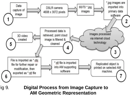
Fig 9. Digital Process from Image Capture to
AM Geometric Representation
The flow chart, shown at Fig.9, details the seven major processes, in capturing digital data by the use of a DSLR camera, to produce between 60 and 70 *.jpg images, which were then imported into the primary digital software. The individual images could then be checked for quality and sent via internet cloud technology to be processed. As Verhoeven [17] points out, the time taken for this process is dependent on the quantity and quality of the images, (as well as internet speed) but a reduction in either can result, as Nguyen
et al show [18], in processed image data which is badly degraded.
Method 2 – Light Tent
As seen from Fig.3, in the “open room” system of data capture, the main subject to be photographed was in a static position and the camera was rotated at a distance of approximately 1.2 to 1.5 metres away, as each image was captured. Suitable shadowless lighting was required from all directions ensuring that there was no light spill into or onto the camera lens. With the light tent system of data capture, depending on the artefact’s size, the camera was placed much nearer the subject, which was then rotated on a turntable as each frame was shot. This method allowed for small objects to be
The screw-on rings should not be confused with macro-lenses, but were used in order to capture more detail. Close-up lens rings were usually labelled +1 to +10 giving a magnification of +0 diopter to +10 diopter.
Fig.10
Alternative method of Data Capture using Light Tent
But being much nearer the subject increased the criticality of the focusing and the depth of field became far more critical; the closer the lens to the subject, the shallower the depth of field became. Shooting at f/5.6 to f/9 in an open roombecame f/18 to f/22+ in a closeup light tent. These smaller apertures required increased illumination on the subject or required longer timed exposures.
There were some similarities between the two methods employed, (Fig.10), but the main difference was that the primary processing software used in this method was Agisoft’s PhotoScan®, rather than 123D Catch®. Instead of processing the data via the internet, as long as the host computer had an i5 or preferably i7 CPU with a minimum 12GB memory [19], the data could be processed on the same computer. The software also allowed for a certain amount of control, by the operator, over how the data was processed. Unfortunately the software did not have the facility to convert the captured images into a video. If required, this could be done using a proprietary video processing program.
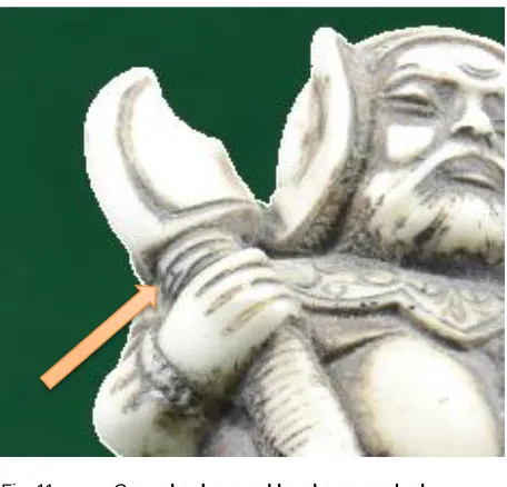
Before the data was processed each image was masked from the surrounding background with a built in tool in the software (Fig.11). A faint white line can be seen (arrowed in Fig.11) that was added by the software to mask out the background colour.
Experimentation with inter-changeable Chroma Key backdrops was undertaken; this type of backdrop provided a very good contrast between the main subject matter and its surroundings. It was found that the time taken to mask each digital image was considerably speeded up with the use of a Chroma Key and in one instance masking was not used at all as the software was able to process the images automatically without the masking process being activated.
[image:6.612.75.299.242.405.2]Kaufman – JCISE -14 - 1238 Page 6 Copyright © 2014 by ASME
Fig. 11 Green background has been masked
out of Warrior Figurine
Once the *.obj file had been obtained the process was the same as for the Open Room method as described above, and the same secondary software was used to produce this type of *.stl file.
CASE STUDY 1. – The Clay Head
The data capture method for the clay head was obtained as described in the previous section using
123D Catch® software, (Fig.5 and Fig.6), to process the data to obtain the point cloud image. It was then cleaned so as to remove any background noise or clutter, as shown in Fig.8. The resulting processed textured 3D mesh showed minor flaws or distortion which had to be corrected, (Fig. 12). The processed photo-textured 3D mesh image head could have been repaired using Studio Pro 4® but by adding and increasing the number of images, with more angled shots and greater image overlap, complex repairs to the point cloud and textured mesh were eliminated. The additional images, once added to the original images, were reprocessed and cleaned.
By selecting the appropriate control in the editing section of 123D Catch®, a wire frame, wire frame and texture, or texture only model can be obtained. This would facilitate in the model repair if required.
Fig.12 Typical Data flaws
[image:7.612.71.299.65.284.2]The final data file of the head (Fig. 14.) was processed to create an *.stl file using Studio Pro4® and then hollowed using the same program. Finally the file was sent to the Stratasys’Dimension® FDM machine to create the physical model.
Fig.13 Original Clay Head Fig.14 Final Textured Digital
Image
The model was instantly recognisable as a copy of the original and although the FDM reproduction is a little smaller than the original; (approx. 80%), the tactile surface finish was much smoother than the rough, prickly feel of the original. This could be attributed to similar geometric errors caused by the size of the extrusion nozzle and tool path of the Dimension® machine on which it was made, as described by Brooks et al.[20].
The Egyptian Collection
The following two objects from the Kendal Museum’s collection were both processed in the same way using Agisoft’s PhotoScan Pro® and the light tent as shown in Fig. 7. The only difference was in the use of the backdrop
Distortion on top of head
Kaufman – JCISE -14 - 1238 Page 7 Copyright © 2014 by ASME each object was.
CASE STUDY 2 and 3.
The Egyptian Vase and Sobekhotep son of Nehesy
There was little difference between these two items in their processing, except that the Chroma Key background for the vase was white and for the figurine it was green. It was thought that the contrasting background would facilitate the masking of each object, preprocessing, by speeding up the time taken to do this manual process; however no conclusive results were obtained. The contrast was perhaps not great enough between the white background and vase, (Fig.15 and 16), and the green background and Sobekhotep, as for the Warrior figurine in Fig.11.
Fig.15 Pre Masking Fig.16 Post Masking
However, when a comparison was made between the digital images taken in the light tent (Fig.15 and 16), and the open room set up, there was a significant increase in the time taken to completely mask the main object, because the background of the open room was so cluttered with irrelevant objects and light reflections, (Fig. 17 and 18). The dotted black lines in Fig. 15 and 18, indicate the outlining of the images requiring to be masked (see arrows), a far more complex operation in Fig. 18 than in Fig.15.
Fig. 17 Pre Masking Fig.18 Complex Masking
the neck of the opening as seen in Fig. 19. The small triangulated mesh as seen in the enlargement screen shot in Fig. 20 is deleted using Studio Pro4®, and the final process on both objects was the hollowing out or shelling,
so as to use less material and reduce their weight. A small hole was made in the base of Sobekhotep so that any unsintered powder could be released, on completion, if it was fabricated on a SLS machine. As the original figurine of Sobekhotep was solid with very little indentations or orifices the processing of the object was much simpler.
Fig. 19 Fig.20
Wire Mesh to be cleaned
RESULTS & DISCUSION
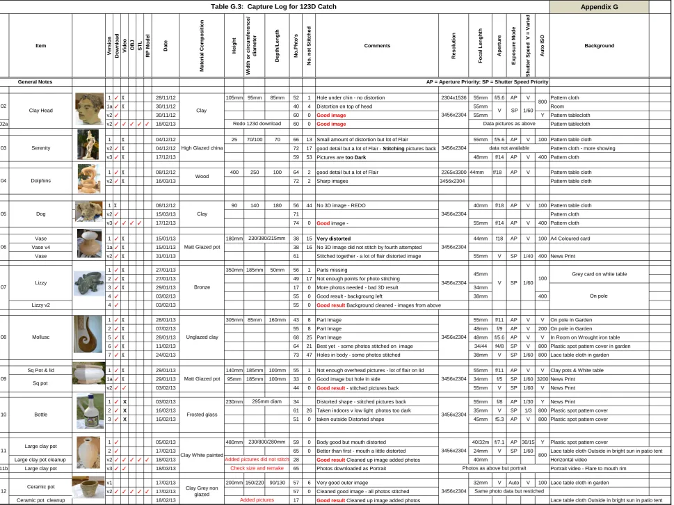
Although only three case studies are discussed in this paper, they come from a series of over 40 objects, all of which were digitally captured using the Nikon DSLR camera, with the data recorded shown in Table 1. The shutter speeds were in fact averages, as the camera was set to aperture priority, leaving it to automatically adjust the shutter speed. The final resolution of each image was 4608 x 3072 megapixels.
The ultimate objective was to turn the original artefact through the use of a data image file, processed by primary and secondary software, into an *.stl file, which AM machines could read without the loss of definition.
It
e
m
N
o.
of
a
tt
e
m
pt
s
N
o.
of
i
m
a
ges
f/
a
per
ture
Foca
l
le
ngth
m
m
S
hutt
e
r
s
pee
d
Head Glazed clay 4 60 f/5.6 55 1/60
Vase Painted clay 2 143 f/10 48 1/15
Figurine Painted clay 1 126 f/18 55 1/3
Table 1. Camera Exposure Data
Kaufman – JCISE -14 - 1238 Page 8 Copyright © 2014 by ASME equipment, and complex computer software, to achieve
good results. It is hoped this photogrammetrical method will eliminate the need for a high level of specialist CAD knowledge in order to process the data obtained from a midrange DSLR camera, to produce virtual 3D images and physical geometric representational models.
CONCLUSIONS & FUTURE WORK
The three models were manufactured using three different types of AM machines, but these models were processed with the minimum of computation, and there was no CAD reconstruction or alteration to the point cloud image or the photo-textured mesh, only minor cleaning; this eliminated the need for software experts, one of the main objectives of the research. If the point cloud image was too badly distorted or holes in the mesh were present, either a new set of images were taken or manual photo stitching of additional photographic images was undertaken. There are obvious exceptions in which the DSLR camera cannot compete, since it can only capture surface images, as in the example of the MRI scanning of the Egyptian mummy by Steele and Williams [21].
Further research is required to investigate how and whether adverse effects can be minimised or eliminated. One of the main problems that was encountered was reflection of highly glazed surfaces or where there was very little surface detail on a very regular shaped item such as a perfectly round, undecorated, highly glazed single colored bowl. In some cases the silhouettes of the objects themselves were so complex that a greater number of images needed to be taken from a greater number of angles. A series of tests using different lighting levels, camera settings such as focal length and depth of field, lens filters, image quantity, and quality and positioning, was required to find a solution, together with the use of the Chroma Key backdrops with greater masking. A suggested starting point might be: less top lighting, a graduated neutral grey filter, perhaps the use of a Polaroid filter or an aperture setting in the region of f/18 to f/21 and slower shutter speeds to compensate for these smaller apertures, but this will mean longer time needed for collecting the data.
By using the same digital image data sets with other primary data processing software, comparisons will be able to be drawn, and a table of pros and cons of the software used, established.
ACKNOWLEDGMENTS
The authors have been granted renewable licenses for the use of Agisoft’s PhotoScan Pro®, Netfabb GmbH’s
Studio Pro5® and DeskArtes’ 3data Expert®. The authors thank Itec3D® and EMCO® for the models that have been made using a Mcor Iris and the Project 660
machines respectively. The authors are grateful and acknowledge the support of all mentioned companies towards this research. All photographic data copyright of the authors unless cited otherwise.
REFERENCES
[1] Zhang Michael, "The World's first Digital Camera," ed: PetaPixel, 2010.
[2] V. Viswanatha, N. B. Patil, and S. Pandey, "Computation of Object parameter Values based on Reference object embedded in Captured Image," Research Journal of Computer Systems Engineering-RJCSE, vol. 02 pp. 183-191, 2011. [3] D. L. Milgram, "Computer methods for creating
photomosaics," Computers, IEEE Transactions on, vol. 100, pp. 1113-1119, 1975.
[4] R. Szeliski, "Image Alignment and Stitching: A Tutorial1," Microsoft Corporation, Redmond,WA 980522006.
[5] Adobe, "PhotoShop Elements," ed. San Jose, CA. USA: Adobe Systems Inc., 2012.
[6] A. West, "20 years of Adobe Photoshop," ed. Vancouver, Canada: WebDesignerDepot, 2010. [7] ASPRS, "American Society for Photogrammetry
and Remote Sensing ", ed. Maryland, USA.: The Imaging & Geospatial Information Society, 1934. [8] AutoDesk, "123D Catch," ed. California, USA:
AutoDesk Inc, 2012.
[9] AgiSoft, "PhotScan," ed. St Petersburg, Russia: Agisoft LLC, 2006.
[10] netfabb, "Studio Professional 4 ", ed. Parsberg, Germany: netfabb GmbH, 2010.
[11] S. G. Barsantia, F. Remondino, and D. Visintini, "3D Surveying and Modelling of Archaeological Sites - some critical issues," ISPRS Photogrammetry,Remote Sensing and Spatial Information Sciences,, vol. II-5/W1, 2013. [12] Anon. (2014). Photogrammetry - Current Suites
of Software. Available: http://en.wikipedia.org/wiki/ Photogrammetry [Accessed 01/01/2014].
[13] MA Media Centre, "Museums Association," ed. London, 2013.
[14] Nikon Corporation, "Nikon ", D3100, Ed., ed. Japan, 2012.
[15] J. Sparks, Nikon D3100, The Expanded Guide. Lewes, UK: Ammonite Press, 2011.
[16] B. Wilde, "Green Screen, a Guide to Chroma Key Photography," in Udemy/blog, ed: Epik Theme - WordPress, 2013.
[17] G. Verhoeven, "Taking computer vision aloft– archaeological 3D reconstructions from aerial photographs with photoscan," Archaeological Prospection, vol. 18, pp. 67-73, 2011.
Kaufman – JCISE -14 - 1238 Page 9 Copyright © 2014 by ASME
international conference on computer graphics, visualisation and computer vision (WSCG 2012), Pilsen, Czech Republic, 2012. [19] Agisoft, PhotoScan Professional Edition. St
Petersberg, Russia: Agisoft LLC,, 2012. [20] H. Brooks, A. Rennie, T. Abram, J.
McGovern, and F. Caron, "Variable fused deposition modelling: analysis of benefits, concept design and tool path generation," in
5th International Conference on Advanced Research in Virtual and Rapid Prototyping., Leiria,Portugal, 2011, pp. 511-517.
Appendix A –
ESDA1014 – Denmark PP presentation June 2014
Page 1
John Kaufman – Lancaster University Engineering Department 1
TRACK 6-1 Additive and digital manufacturing
Session Schedule: Thursday, June 26, 2014 01:30pm - 03:30pm u1
Slide 1
John Kaufman – Lancaster University Engineering Department 2
u1
Slide 2
John Kaufman – Lancaster University Engineering Department 3
u1
Slide 3
John Kaufman – Lancaster University Engineering Department
4
G. Hare – London c1857
Early 2D (stereoscopic) camera and double image photographs
Offset images
Slide 4
John Kaufman – Lancaster University Engineering Department
5
Kilbourne Stereoscope c1868
Lenticular Stereoscope c1860
Victorian stereoscopic viewers with Retro equivalent
ViewMaster c1960
Slide 5
John Kaufman – Lancaster University Engineering Department
-6
Digital Photographic Data Capture
Sassoon's Digital camera
-0.01 Megapixels - c1975
Nikon D3100 – 14.2 Mgp
ESDA1014 – Denmark PP presentation June 2014
Page 2
John Kaufman – Lancaster University Engineering Department7
Raison d’être for my research
A simpler, more accessible way of data capture and processing
Therefore the technology can be used by computer-literate but not necessarily expert computer program operatives
More cost effective than Laser Scanner
Can be used
by:-• Community projects
• Education, visually impaired, museums etc.
• Promotional exploitation by small businesses
It can replicate unique objects in a non-invasive way
Slide 7
John Kaufman – Lancaster University Engineering Department -8
2D Digital Images into
Additive Manufactured replicated models
The Research used a Single Digital SLR Camera and Computer Software to transform
Slide 8
John Kaufman – Lancaster University Engineering Department 9
Two distinctly different processes are examined.
Cloud processing using – AutoDesk’s 123D Catch
“Open Room” Digital Image capture The Camera is moved around the subject
Computer processing using –Agisoft’s PhotoScan Pro
“Light Tent” Digital Image capture The Camera is stationary as the subject is rotated
The resulting Image Data Capture in both methods is then processed by Netfabb’s Studio Pro5 or with DeskArt’s 3data Expert if colour models are required
Slide 9
John Kaufman – Lancaster University Engineering Department 10
Indoor Open Room ‘studio’ setup
Slide 10
John Kaufman – Lancaster University Engineering Department 11
Digital Image to AM Geometric Replication using 123D Catch cloud processing
Slide 11
John Kaufman – Lancaster University Engineering Department
-12
Take the Pictures:– 60 to 70+ digital images from 360
Appendix A –
ESDA1014 – Denmark PP presentation June 2014
Page 3
John Kaufman – Lancaster University Engineering Department 13
60 – 70 images
Camera positions in the horizontal plain
Horizontal positioning
15 - 20
Slide 13
John Kaufman – Lancaster University Engineering Department 14
Camera positions in the vertical plane
Vertical positioning
Slide 14
John Kaufman – Lancaster University Engineering Department
-15
The camera is moved around the subject both in the horizontal and vertical plane 360° and30/40° respectively
Slide 15
John Kaufman – Lancaster University Engineering Department 16
Repairing the point cloud image
Hole under chin
Returned Virtual Digital Point Cloud Images need to be cleaned
Slide 16
John Kaufman – Lancaster University Engineering Department 17
Adding Photographic Data to repair Point Cloud Image
Selected photo image Matching points
1
1 1
2
2 2
3
3 4
3
4
4
Slide 17
John Kaufman – Lancaster University Engineering Department -19
*.STL file
Studio Professional netfabb GmbH - Germany
The virtual image is processed and sent to AM machine
*.obj file – virtual image
FDM model FDM Model
hand painted
ESDA1014 – Denmark PP presentation June 2014
Page 4
John Kaufman – Lancaster University Engineering Department
20
“Light Tent” and turntable
Slide 19
John Kaufman – Lancaster University Engineering Department
21
Working with a Green “Chroma key” background
Slide 20
John Kaufman – Lancaster University Engineering Department
22
Digital Image to AM Geometric Replication using
PhotoScan& computer processing
Slide 21
John Kaufman – Lancaster University Engineering Department 23
Camera positions in the vertical plane
Slide 22
John Kaufman – Lancaster University Engineering Department 24
Camera positions in the horizontal plane – 100\140 images
Artefact rotated on turn table
10/15°
Slide 23
John Kaufman – Lancaster University Engineering Department 25
PhotoScan requires pre-masking of images
Appendix A –
ESDA1014 – Denmark PP presentation June 2014
Page 5
John Kaufman – Lancaster University Engineering Department 26
Point Cloud
Solid - *stl file
Shaded *.obj file
Wireframe Stages in processing
virtual image
Area to be cleaned
Slide 25
John Kaufman – Lancaster University Engineering Department 27
Clay Head
FDM model
Sobekhotep
Egyptian Vase Hand painted FDM
Egyptian Bowl
DTM 2000 SLS Projet 660 model SLS
Slide 26
John Kaufman – Lancaster University Engineering Department 28
Point Cloud file image screen shots.
Slide 27
John Kaufman – Lancaster University Engineering Department
-30
Thank you for your attention
Any Questions???
John Kaufman - [email protected]
Slide 28
John Kaufman – Lancaster University Engineering Department -29
Acknowledgments
Agisoft PhotoScan Professional edition
Kendal Museum - the Egyptian collection
excavated by John Garstang in c1902, and donated by John Rankin, an original sponsor
Agisoft’s - PhotoScan Pro
AutoDesk – 123D Catch
DeskArtes’ – 3data Expert
Netfabb GmbH’s – Studio Pro5
CIRP – published on line – Sciencedirect.com
CIRP – Procedia CIRP vol. 36
Papers - 2015
CIRP 25
thDesign Conference – Innovative Product Creation
John Kaufman - CIRP 25th Design Conference
1
Single Camera Photogrammetry for Reverse Engineering and
Fabrication of Ancient and Modern Artifacts
John Kaufman – [email protected] - Engineering Dept., Lancaster University, Lancaster. LA1 4YR - UK Allan EW Rennie – [email protected] - Engineering Dept., Lancaster University, Lancaster. LA1 4YR - UK
Morag Clement – [email protected] – Kendal Museum, Kendal. Cumbria. LA9 6BT - UK
ABSTRACT:
Photogrammetry has been used for recording objects for well over one hundred and fifty years. Modern photogrammetry, or digital image capture, can be used with the aid of a single medium range digital single lens reflex (DSLR) camera, to transform two-dimensional images into three-dimensional CAD spatial representations, and together with the use of additive manufacturing or 3D Printing technology, geometric representations of original cultural, historic and geological artifacts can be fabricated in a process known as Reverse Engineering. Being able to replicate such objects is of great benefit in education; if the original object cannot be handled because it is too old or delicate, then replicas can give the handler a chance to experience the size, texture and weight of rare objects. Photogrammetry equipment is discussed, the objective being simplicity of execution for eventual realisation of physical products such as the artifacts discussed. As the processing power of computers has increased and become more widely available, and with the use of computer software programs it is now possible to digitally combine multi-view photographs, taken from 360° around the object, into 3D CAD representational virtual images. The resulting Data is then reprocessed, with a secondary computer program, to produce the STL file that the additive manufacturing machines can read, so as to produce replicated models of the originals. Three case studies are documented: the reproduction of a small modern clay sculpture; a 3000-year-old Egyptian artifact; and an Ammonite fossil, all successfully recreated, using additive manufacturing technology.
KEY WORDS: photogrammetry; reverse engineering; DSLR camera; non-invasive reproduction; 123D Catch; PhotoScan; Studio Pro5; cultural heritage; education; additive manufacture.
1. INTRODUCTION
Three-dimensional (3D) imaging has been in existence since the invention of Lenticular’s Stereoscope in 1860. Thus, the idea of a two-dimensional (2D) image being converted to a 3D image is not new. Photogrammetry, as it is sometimes referred to, “is as old as modern photography” (1) and dates from the mid-nineteenth
century. Since the late 1990’s, Laser Scanning (LS) has moved to the predominant non-invasive method used to replicate both large and small objects, such as large historic buildings and small statues [1].
The first digital camera was invented in 1975 by Sasson, who was an engineer working for Eastman Kodak® (2). These cameras have developed from the low resolution 0.01megapixel early camera to 60 or 80 megapixels at the top end of today’s professional range. Photo-manipulating/enhancing computer programs have been able to stitch 2D digital photo images together for a number of years, creating panoramic views of city, sea or landscapes (3). More recently, with the help of i5 and i7 CPUs and the large amount of RAM that modern computers can now accommodate, software is available which is capable of stitching 150 or more, high resolution digital images together to form a virtual 3D representational image (4). The reconstruction of 3D models is semi-automatic due to reconstruction problems and requires user intervention.
2. RESEARCH OBJECTIVES
In this paper, it is shown that with the use of photogrammetry, virtual 3D models can be created, without a high level of computer expertise and without the use of relatively expensive or complicated 3D laser scanning equipment. Many software programs claim to be able to convert 2D digital photographs into 3D virtual images. On investigation, it has been found that many are still in development and are not necessarily available for use except experimentally. Several commercial computer programs are available with a proven and reliable record to “stitch” multi-view digital images together to produce a 3D image.
John Kaufman - CIRP 25th Design Conference
2
Two programs were used in this research for the primary software processing of the digital images (4, 5). In addition, the high resolution point cloud images produced were filtered and converted to STL files by a third program (6), ready for additive manufacturing (AM) machines to replicate and produce geometric representational models. The use of this technique could contribute to the reproduction, restoration or repair of damaged or broken antiquities by non-invasive methods at modest cost and by laypersons, who are computer literate but not necessarily expert in the use of specialised software.
By using a relatively modest DSLR camera, expensive LS is not required to capture the data necessary to produce 3D virtual images, and experienced technicians are no longer required to operate such equipment. A comparison between photogrammetry and laser scanning, their techniques and characteristics has been shown in Barsantia et al (7). The primary research task investigates how well these software programs convert the digital 2D image into AM models, and compares results obtained with the original object. The research investigates the tactile surfaces of the replicated models and compares them to the original objects; it considers whether those replicated models, when scaled up and down, lose surface detail and whether the AM models created could be substituted for the original.
3. DATA CAPTURE METHODS
One of the main objectives of the research was concentrating on the ease of reproducing artifacts without complex hardware or software. A mid-range Nikon D3100® DSLR camera was used, the digital data obtained being in JPG, or common image format. A standard fixed focus prime 50mm lens, which has a wide f1.4 or f1.8 aperture and minimum lens distortion and very good depth of field, was considered, but a Nikon 18/55mm DX® auto focus lens was chosen, being directly compatible with the camera and able to automatically refocus around the subject from the many positions and angles encountered. Minimum lens distortion was achieved by keeping to the higher focal length end of 35/55mm on the lens. The disadvantage of this lens as opposed to a fixed lens is that the depth of field is not as good and slower shutter speeds are required as the aperture is not as wide. A resolution of 3456 x 2304 pixels per frame was used throughout, which equates to approximately 8 megapixels.
Method 1 – open room set-up
The method of lighting and camera positioning for the artifacts were different in each case study, the common factor being that shadowless, flat lighting was required to illuminate all the artifacts, as any shadow distorted the image captured and processed by the software. The same was true for any highlights or reflections that the lighting might have caused. In Fig.1 the windows are covered so as to diffuse the natural daylight and help create a shadowless room. The main indoor lighting consisted of two bip® fluorescent floodlight control units on telescopic stands, each with three separate switched 50W 5000K bulbs and white defusing front covers and, if needed, two small lamps with 45W 5500K bulbs. Indirect daylight was utilised if available. Any small difference in colour temperature, known as White Balance, was automatically adjusted by the D3100 camera
“as digital cameras have a far greater capacity to compensate for the varying colours of light” (8).
The first study, a small modern clay head sculpture, has been included to show a comparative method in both AM printing and data capture. This semi-glazed painted head, measuring 105mm x 95mm x 85mm, was placed in the centre of a room on a pedestal whilst the camera was moved in a full circle around the object and a digital image captured every 20o. The model clay head is seen, arrowed, in the centre of the room (Fig.1).
CIRP 25
thDesign Conference – Innovative Product Creation
John Kaufman - CIRP 25th Design Conference
3
[image:19.595.85.524.171.339.2]returned data image was then cleaned and the file was processed using Netfabb’s Studio Pro4® to produce the STL file which the Stratasys’ Dimension®Fused Deposition Modelling (FDM) machine could accept and use to fabricate the model.
Fig. 1 Indoor Open Room Setup Fig. 2 Multi Camera positioning around Clay Head
Method 2 – Light Tent
The second method of digital data capture used a collapsible Light Tent; (Fig.3). This was constructed specifically for this purpose, from 20mm plastic tubing and suitable angle corners to make a metre square enclosure, covered in white poplin fabric with a front opening. So as to obtain strong contrast between the subject matter that was being photographed, interchangeable Chroma Key [8] backdrops were used, either white or green, depending on the colour of the subject. As seen in Fig.3, the lights were placed outside the tent allowing the fabric to soften the lighting and disperse any shadows. Natural light coming from the window behind (unshaded) helped to counteract any shadows.
Fig 3 Light Tent in Kendal Museum Fig.4 Green Chroma Key backdrop and open-sided light tents
The light tent was used to digitally capture images of the artifacts from antiquity, a 3000 year old Egyptian figurine, and an Ammonite fossil and processed using Agisoft’s PhotoScan Pro®. Netfabb’s Studio Pro4® was then used to produce the STL file which the AM machine requires in order to print the replications. The models that were made using this technique were processed on a 3D Systems DTM Sinterstation®, Selective Laser Sintering (SLS) machine, in a plain white Nylon 12 (polyamide). The light tent used to capture the Ammonite data was different in that the white linen cover was not used, as the natural light in the indoor environment was very soft and it was felt that only a small amount of “fill in” artificial light was needed. However a contrast green backdrop was used to enhance the contrast with the greyish colored Ammonite (Fig 4). In both Fig. 3 and Fig. 4 a turntable can be seen which was used to revolve the artefact around 360o. The
[image:19.595.328.525.173.308.2] [image:19.595.92.524.463.616.2] [image:19.595.89.307.466.607.2]John Kaufman - CIRP 25th Design Conference
4
camera was stationary, only being moved once in the vertical plane for every complete revolution of the subject.
Data Processing
In 2011, Verhoeven (9) using stereoscopic photography, and after processing the digital images (4), produced a series of virtual 3D images. It was noted that although the software claimed to be able to process, in theory, a very large number of photographs, in practical terms this is a maximum of approximately 1024 images. Verhoeven records that the relationships between the processing time, speed, quantity and high resolution data, are all interlinked. The more detailed the photogrammetric data, the greater the speed of processor required with a computation time penalty.
For the clay head, three attempts were made, gradually increasing the number of images from 40 to 70, which were taken from different angles, encircling and arcing around the object from above and below. This ensured that there was an image overlap of about 15-20%. Using one of the primary software programs, the images were processed to generate point cloud data sets (5). This program used internet web-based cloud services provided by Autodesk to turn the JPG processed data, taken from the camera, into image formats for importing into third party software programs. Using this software, a video could be created by selection or rejection of the 60 photographic images in the path the images had taken. The software seamlessly converted the images selected into a moving 3D virtual representation. The time taken for this process was dependent on the quantity and quality of the images (as well as internet speed), but a reduction in either could result, as Nguyen et al show [10], in processed image data which is badly degraded. The data image having been cleaned, it was then exported as an OBJ file and a 3D textured mesh was created.
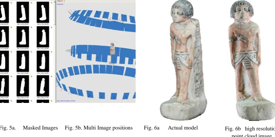
[image:20.595.85.529.496.717.2]The other two items were photographed using the light tent: Sobekhotep, the Egyptian figurine and the Ammonite fossil were processed in the same way to each other. As seen from Fig.1, in the “open room” system of data capture, the main subject, in this case the clay head, was in a static position and the camera was rotated at a distance of approximately 1.2 to 1.5 metres away. With the light tent system of data capture, depending on the artifact’s size, the camera was placed much nearer the subject. The artifact was then rotated on a turntable between 10o and 15o, as each frame was shot (Fig.5).
Fig. 5a. Masked Images Fig. 5b. Multi Image positions Fig. 6a Actual model Fig. 6b high resolution point cloud image
CIRP 25
thDesign Conference – Innovative Product Creation
John Kaufman - CIRP 25th Design Conference
5
taken. But being much nearer the subject increased the criticality of the focusing and the depth of field became far more important; the closer the lens to the subject, the shallower the depth of field became. Shooting at f/5.6 to f/9 in an open room became f/18 to f/22+ in a light tent. These smaller apertures required increased illumination on the subject or required longer timed exposures.
In this method, the software (4) also allowed for more control, by the operator, over how the data was processed. Instead of processing the data via the internet as with the first example, and as long as the host computer had an i5 or preferably i7 CPU with a minimum 12GB memory the data could be processed on the same machine. Before processing the data, each image was masked from the surrounding background with a built in tool in the software, as can be seen in Fig.5a. The actual original model (Fig.6a) shows no discernable loss of detail compared to the screen shot of the high point cloud data image (Fig.6b).
Experimentation with inter-changeable Chroma Key backdrops was undertaken; this type of backdrop provided a very good contrast between the main subject matter and its surroundings. It was found that the time taken to mask each digital image was considerably quicker with the use of a Chroma Key background. The more RAM that was available, the faster the digital data could be processed, and the more detail that was forthcoming. Unfortunately the software did not have the facility to convert the captured images into a video. If required, this could be done using a proprietary video processing program.
[image:21.595.89.530.366.512.2]4. REPAIR of NOISY, DISTORTED and INCOMPLETE DATA
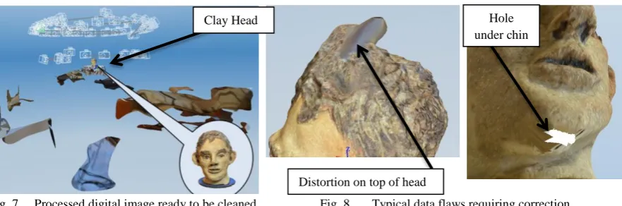
Fig. 7 Processed digital image ready to be cleaned Fig. 8 Typical data flaws requiring correction
The returned processed point cloud image, as seen in Fig.7; (head identified) had to be filtered, or cleaned, to eliminate background noise that had been captured along with the original subject, such as other objects or furniture that were in the line of focus when the image was recorded by the DSLR. The resulting processed textured 3D mesh showed minor flaws or distortion which had to be corrected (Fig. 8). The processed photo-textured 3D mesh image head could have been repaired using software, but by adding and increasing the number of images, with more angled shots and greater image overlap, complex repairs to the point cloud and textured mesh were eliminated. The additional photographic digital images, once added to the original data set of images, were reprocessed and sent by the internet to be cloud processed and returned ready to be recleaned. By selecting the appropriate control in the editing section, a wire frame, wire frame and texture, or texture only model could be obtained. This would facilitate the model repair if required.
5. THE FINAL MODEL
The OBJ file was created as a solid, but by hollowing the model, using this secondary software, the amount of material, and therefore its weight, was reduced; this could be in the region of 80% of the mass, making a great difference to the final material cost of manufacturing using AM. The model that was then made was instantly recognisable as a copy of the original and although the FDM reproduction was a little smaller than the original (approximately 80%), the tactile surface finish was much smoother than the rough, prickly feel of the original
Clay Head
Distortion on top of head
John Kaufman - CIRP 25th Design Conference
6
clay surface. This could be attributed to similar geometric errors caused by the size of the extrusion nozzle and tool path of the Dimension® FDM machine on which it was made, as described by Brooks et al. [9].
[image:22.595.93.534.207.383.2]The quality of build is well known (10) (11), as can be appreciated by the differences between the use of an entry level FDM machine costing a few hundred £/€ to that of a SLS machine costing several hundred thousand £/€, thus resulting in how much detail of the original model was lost or captured.
Fig. 9 Original Clay model Fig.10 Virtual Point Cloud image Fig.11 Hand painted FDM model
6. SCALE and PHYSICAL DETAIL of AM MODELS.
It was found that the resulting dimensions of the 3D image obtained from the primary software very rarely matched the original dimensions of the object photographed, being created in a virtual arbitrary scale. For large objects such as buildings or monumental structures, this is a problem, but it is not within the scope of this paper, which only concerns itself with smaller sized artifacts, that can be easily measured. The scaling feature which exists in the Studio Pro 4® software program is of great importance, as the final dimensional accuracy of the finished AM replicated artefact can be fine-tuned. By simply comparing the size of the 3D virtual model with the original, and by adjusting the percentage increase needed to scale up the model within the software, an exact dimensional copy was obtained in all x, y, z planes. The operator has a certain amount of control when using PhotoScan Pro®, for example, to process the final 3D point cloud image; but even this control was limited to the processing capacity of the computer. Guidi, et al, (12) discussed the control that the operator has over this software, a semi-automatic commercial software program
Mesh type Ultra High Medium Ultra Low
Polygons 4,846,416 527,150 460,304
[image:22.595.98.533.576.743.2]STL file size 236,642 kb 25,740 kb 22,476 kb Fig. 12 Ammonite Fossil - wire mesh screen shots – Mesh types vs Number of polygons
CIRP 25
thDesign Conference – Innovative Product Creation
John Kaufman - CIRP 25th Design Conference
7
However, in processing a range of artifacts in this research, the following factors played a key role in determining the time taken and quality achieved: the difference in the “Build Dense Cloud” function between
Ultra High to Ultra Low (Fig.12); the fact that a specification of an i7 CPU was being used; and whether the computer had 16MB or 32MB RAM. Only the smallest of objects with a relatively simple profile, could be processed with 16MB RAM using Ultra High setting. The processing times in the Ammonite fossil seen in Fig.12, increased from around 30-45 minutes for the Ultra-Low build (using16MB RAM) to up to 6 or 8 hours for Ultra High (using 32MB RAM), as well as increasing the size of the final STL file: which then was reflected in the quality of the AM build. This ultra-high detail of the build was in itself controlled by the capabilities of the AM machine used, whether the machine could print in layers of say (typically) 100microns or (with recent advances) 16microns..
7. CONCLUSIONS & FUTURE WORK
The digital date for these artifacts, were all captured, using a single mid-range DLSR camera. The models were manufactured using different types of AM machines, but these models were processed with the minimum of computation. There was no CAD reconstruction or alteration to the point cloud image or the photo-textured mesh, only minor cleaning; this eliminated the need for software experts, one of the main objectives of the research. If the point cloud image was too badly distorted or holes in the mesh were present, either a new set of images were taken or manual photo stitching of additional photographic images was undertaken. There are obvious exceptions in which the DSLR camera cannot function, since it can only capture surface images unlike volumetric scanning, or as in the examples of the MRI scanning of an Egyptian mummy by Steele and Williams (12) or the use of CT scanning and computer assisted surgical planning, combined with patient-specific surgical guides for patients with deformed bone structures as in the work of Leong et el (13). But for this research using the DSLR, it is only the surface data which is required to produce the geometric representation artifacts.
Further research is required to investigate how and whether adverse effects can be minimised or eliminated at the data capture stage. One of the main problems that was encountered was reflection of highly glazed surfaces. In some cases the silhouettes of the objects themselves were so complex that a greater number of images needed to be taken, thus slowing down the processing time. A series of tests using lower lighting levels, camera settings, lens filters, data pixel image size, is required to find a solution. A suggested starting point might be: graduated neutral grey filters, perhaps the use of a Polaroid filter, or aperture setting even smaller than f/18 or f/21, compensated by slower shutter speeds, but this means a longer processing time penalty. Ultimately, as stated, monetary budget is a very important factor, as to the final detail and standard of finished product. Both processing and build time will ultimately be reflected in the quality of the final version of the model.
Coloration of the replicated artifacts needs further work, as can be seen in differences between Figures 9 and 11. The original clay head (Fig.9) was painted using pottery glazes, then ‘fired’, producing quite a different look to the brighter pigmentation of the Acrylic paints used on the FDM model (Fig.11). Water colour paints, which are more subtle than oil or acrylic paint, were tried, but would not dry properly on the nylon material from which the FDM model was made. Printing or painting on a sandstone material, in this instance, may have produced a better result. Producing models using a series of different materials, types of paint or inks, including a colour printer, might yield results nearer to the original coloration.
However, it has clearly been shown that simply with the use of a single DSLR camera, user friendly software and AM technology, both modern and ancient artifacts have been reversed engineered and replication models fabricated.
Acknowledgements
John Kaufman - CIRP 25th Design Conference
8
References
1. Viswanatha V, Patil NB, Pandey S. Computation of Object Parameter Values based on Reference Object Embedded in Captured Image. Research Journal of Computer Systems Engineering - RJCSE. 2011;02 (04, July-Sept):183-91.
2. CadeZhang M. The World's first Digital Camera. In: Cade D, editor. Davis,San Francisco, USA.: PetaPixel; 2010.
3. Adobe. PhotoShop Elements. San Jose, CA. USA: Adobe Systems Inc.; 2012. 4. Agisoft. PhotoScan Professional Edition. St Petersberg, Russia: Agisoft LLC; 2012.
5. AutoDesk. 123D Catch. California, USA: AutoDesk Inc; 2012. p. a suite of hobbyist CAD and 3D modelling tools
6. netfabb. Studio Professional 4 Parsberg, Germany: netfabb GmbH; 2010. p. Provider of Additive Manufacturing software solutions.
7. Barsantia SG, Remondino F, Visintini D, editors. 3D Surveying and Modelling of Archaeological Sites - some critical issues. ISPRS Photogrammetry,Remote Sensing and Spatial Information Sciences,; 2013; Strasbourg,France.
8. Sparks J. Nikon D3100, The Expanded Guide. Wiles R, editor. Lewes, UK: Ammonite Press; 2011. 9. Verhoeven G. Taking Computer Vision aloft – Archaeological 3D Reconstructions from Aerial Photographs with PhotoScan. Archaeological Prospection. [Software Review]. 2011 20 January;18(1):67-73. 10. Zeng K, Patil N, Gu H, Gong H, Pal D, Starr T, et al., editors. Layer by Layer Validation of Geometrical Accuracy in Additive Manufacturing processes. Proceedings of the Solid Freeform Fabrication Symposium; 2013; Austin, Texas, USA.
11. Brooks H, Rennie A, Abram T, McGovern J, Caron F, editors. Variable fused deposition modelling: analysis of benefits, concept design and tool path generation. 5th International Conference on Advanced Research in Virtual and Rapid Prototyping; 2011; Leiria,Portugal: CRC Press - Taylor&Francis Group. 12. Steele K, Williams R. Reverse engineering the Greek comic mask using photographic three-dimensional scanning and three three-dimensional printing techniques and related seepage control. . Rapid and Virtual Prototyping and Applications : 4th National Conference. 2003:73-81.
Appendix B
CIRP 25
thDesign Conference – Israel pp presentation March 2015
Page 1
1
PhD student
Slide 1
John Kaufman – Lancaster University Engineering Department 2
Single Camera Photogrammetry
for Reverse Engineering
and Fabrication of
Ancient and Modern Artifacts
Slide 2
3G. Hare – London c1857
Early 2D (stereoscopic) camera and double image photographs
Offset images
Slide 3
4
Kilbourne Stereoscope c1868
Lenticular Stereoscope c1860
Victorian stereoscopic viewers with Retro equivalent
View Master c1960
Slide 4
5Digital Photographic Data Capture
Sassoon's Digital camera -0.01 Megapixels - c1975
Nikon D3100 – 14.2 Megapixels
Slide 5
6Raison d’être for my research
To develop simpler, more accessible way of data capture & processing
Therefore the technology can be used by computer-literate but not necessarily expert computer software operatives
The system is more cost effective (cheaper) than Laser Scanner
Can be used
by:-• Community projects
• Education, visually impaired, museums and galleries etc.
• Small businesses for promotional exploitation It can replicate unique objects in a non-invasive way