University of Warwick institutional repository: http://go.warwick.ac.uk/wrap
A Thesis Submitted for the Degree of PhD at the University of Warwick
http://go.warwick.ac.uk/wrap/77145
This thesis is made available online and is protected by original copyright. Please scroll down to view the document itself.
Bio-integrative Polymer
Surfaces
Caroline Imogen Biggs
A thesis submitted in partial fulfilment of the requirements for
the degree of Doctor of Philosophy in Chemistry
University of Warwick
Department of Chemistry
i
Table of Contents
List of Figures xi
List of Tables xxiii
Acknowledgements xxv
Declaration xxvi
Abstract xxvii
Abbreviations xxviii
Colour Code for Graphs xxxi
Chapter One
1. Introduction 1
1.1. Glycoarrays 1
1.1.1. The Antibiotic Problem 1
1.1.2. Protein-Carbohydrate Interactions 2
1.1.3. Bacterial Cell Adhesion 6
1.1.4. Glycoarray Technology 7
1.2. Polymerisations 14
ii
1.2.2. RAFT Polymerisation 15
1.2.3. End group Modification of RAFT Polymers 18
1.2.4. Characterisation of Polymers 21
1.2.5. Thermally-Responsive Materials 22 1.2.6. Thiol-Ene “Click” Reactions and their Polymer Applications 26
1.3. Surface Grafted Polymers 29
1.3.1. Techniques for Surface Grafting 29 1.3.2. Applications of Polymer Coated Surfaces 34
1.4. Surface Analysis 40
1.4.1. Drop Shape Analysis 40
1.4.2. Ellipsometry 42
1.4.3. X-Ray Photoelectron Spectroscopy (XPS) 42 1.4.4. Quartz-Crystal Microscopy with Dissipation (QCM-D) 43 1.5. “Switchable” Polymer Coatings for Microarray Applications 47
1.6. Aims 48
1.7. References
iii
Chapter Two
2. Thiol-ene Immobilisation of Carbohydrates onto Glass and Silicon Surfaces
57
2.1. Chapter Summary 57
2.2. Introduction 58
2.3. Results and Discussion 60
2.3.1. Glass and Silicon Surfaces 60
2.3.2. Functionalisation with Acryloyl Chloride 61 2.3.3. Functionalisation with Silanes 65 2.3.3.1. Solution Phase Silanisation 65 2.3.3.2. Optimising the Silanisation 69 2.3.3.3. UV/Ozone Cleaning and Vapour Phase Silanisation 69 2.3.4. Surface Analysis by Ellipsometry 72
2.3.5. Surface Analysis by XPS 74
2.3.6. Lectin Binding Studies 77
2.3.7. Microtitre Plates 79
2.4. Conclusions 84
2.5. Materials and Methods 85
iv
2.5.2. General Surface Analysis 86
2.5.2.1. Contact Angle Measurements 86
2.5.2.2. Ellipsometry 86
2.5.2.3. X-ray Photoelectron Spectroscopy 87
2.5.2.4. Microarray Scanner 88
2.5.3. Surface Modification 89
2.5.3.1. Piranha Cleaning 89
2.5.3.2. UV/ Ozone Cleaning 89
2.5.3.3. Acryloyl Chloride Functionalisation 90 2.5.3.4. Thiol-ene “Click” Functionalisation of the Acrylate Surfaces 90 2.5.3.5. Solution Phase Silanisation 90
2.5.3.6. Vapour Phase Silanisation 90
2.5.3.7. Thiol-ene “Click” Functionalisation of Silane Coated Surfaces 91
2.5.4. Lectin Binding Studies 91
2.5.5. Microtitre Plate Functionalisation 91 2.5.5.1. Solvent Compatibility Testing 91 2.5.5.2. Acrylation of Amine Coated Plates 92 2.5.5.3. Microplate Reader Measurements 93
v
Chapter Three
3. Surface Grafting RAFT Synthesised Polymers and a Comparison between pOEGMA and pNIPAM
96
3.1. Chapter Summary 96
3.2. Introduction 98
3.3. Results and Discussion 102
3.3.1. Polymerisation 102
3.3.1.1. Synthesis of poly(oligo(ethylene glycol)methyl ether methacrylate)s
102
3.3.1.2. Synthesis of 2-(dodecylthiocarbonothioylthio)-2-methylpropanoic acid
105
3.3.1.3. Synthesis of poly(N-isopropylacrylamide)s 106 3.3.2. Polymer Coatings on Silane Functionalised Surfaces 109 3.3.2.1. Formation of Polymer Coatings on Glass and Silicon 109 3.3.3. Analysis of the Polymer Coated Surfaces 110
3.3.3.1. Drop Shape Analysis 110
3.3.3.2. Ellipsometry 112
3.3.3.3. X-ray Photoelectron Spectroscopy 114 3.3.4. Non-fouling Behaviour of Polymer Functionalised Surfaces 120 3.3.5. Thermoresponsive Behaviour of Polymer Functionalised
Surfaces
vi
3.3.6. QCM-D Studies into Gold-Polymer Binding 132 3.3.6.1. POEGMA Binding with and without the RAAFT End Group 132
3.3.6.2. PNIPAM Binding 141
3.3.6.3. Comparison of the Binding of pNIPAM and pOEGMA 144 3.3.6.4. QCM-D to Demonstrate Thermo-responsive Behaviour 148 3.3.7. QCM-D Studies into Silicon-Polymer Binding 151 3.3.7.1. Polymer Binding with and without the Silane Acrylate 151 3.3.7.2. Static Silicon QCM-D measurements 155
3.4. Conclusions 157
3.5. Materials and Methods 158
3.5.1. General Experimental 158
3.5.1.1. Nuclear Magnetic Resonance Spectroscopy 159 3.5.1.2. Size Exclusion Chromatography 159 3.5.1.3. Cloud Point Measurement (Turbidimetric Analysis) 159
3.5.1.4. Infrared Spectroscopy 160
3.5.1.5. Mass Spectrometry 160
3.5.1.6. Surface Cleaning Procedure 160
3.5.2. General Surface Analysis 161
vii
3.5.2.2. Ellipsometry 161
3.5.2.3. X-ray Photoelectron Spectroscopy 162
3.5.2.4. Microarray Scanner 163
3.5.2.5. Quartz Crystal Microbalance with Dissipation 163
3.5.3. Polymerisations 165
3.5.3.1. Synthesis Poly(oligo(ethylene glycol) methyl ether methacrylate)s
165
3.5.3.2. Synthesis of 2-(dodecylthiocarbonothioylthio)-2-methylpropanoic acid
167
3.5.3.3. Synthesis of poly(N-isopropylacrylamide)s 168 3.5.4. Polymer Coatings on Silane Functionalised Surface 170 3.5.4.1. Glass and Silicon Surface Functionalisation 170 3.5.4.2. Non-fouling Behaviour of Polymer Functionalised Surfaces 170 3.5.4.3. Thermoresponsive Behaviour of Polymer Functionalised
Surfaces
171
3.5.4.3.1. Direct Heating of Glass slides 171 3.5.4.3.2. Hot Plate Heating of Glass Slides 171 3.5.4.3.3. Temperature Controlled Stage Facilitated Heating and Cooling
of Glass Slides
172
viii
Chapter 4
4. Contact Printing of Glycopolymers 176
4.1. Chapter Summary 176
4.2. Introduction 178
4.3. Results and Discussion 184
4.3.1. Comparison of Silane Coating and Commercially Available Epoxide Coatings
184
4.3.2. Synthesis of Glycosylated Polymers 186 4.3.2.1. Synthesis of PFP RAFT Agent 186 4.3.2.2. Synthesis of Pentafluorophenyl Terminated pNIPAM Polymers 188 4.3.2.3. Glycosylation of PFP-pNIPAM polymers 191 4.3.3. Immobilisation of Glycopolymers onto Glass Substrates 196 4.3.3.1. Drop Shape Analysis of the Glycopolymer Functioalised Glass 196 4.3.4. Interaction of Surface Bound Glycopolymers with Lectins 198 4.3.5. Direct-Microcontact Printing of Glycopolymers onto Glass 205 4.3.6. Interaction of Printed Glycopolymers with Lectins 207
4.4. Conclusions 210
4.5. Materials and Methods 211
ix
4.5.1.1. Nuclear Magnetic Resonance Spectroscopy 211 4.5.1.2. Size Exclusion Chromatography 212 4.5.1.3. C loud Point Measurements (Turbidimetric Analysis) 212
4.5.1.4. Infrared Spectra 212
4.5.1.5. Mass Spectrometry 213
4.5.1.6. Surface Cleaning Procedure 213
4.5.2. General Surface Analysis 214
4.5.2.1. Contact Angle Measurements 214
4.5.2.2. Microarray Scanner 214
4.5.3. Synthetic Procedures 215
4.5.3.1. Synthesis of PFP-RAFT Agent 215 4.5.3.2. Synthesis of PFP-pNIPAM polymers 216 4.5.3.3. Glycosylation of PFP-pNIPAMs 218 4.5.4. Glycopolymer Coatings on Glass Substrates 218 4.5.4.1. Functionalisation of Plain Microscope Slides 218 4.5.4.2. Functionalisation of Epoxide Coated Glass 219 4.5.5. Direct Micro-Contact Printing of Polymers onto Glass 220 4.5.6. Lectin-Glycopolymer Interactions 220
x
Chapter 5
5. Conclusions 223
Appendix One
XPS Spectra for Monosaccharide and Polymer Functionalised Surfaces 225
ESI Mass Spectrum for PFP-pNIPAM 227
Appendix Two - Publications
Probing the Biomimetic Ice Nucleation Inhibition Activity of Poly(vinyl alcohol) and Comparison to Synthetic and Biological Polymers
228
xi
List of Figures
Chapter One
Figure 1.1: The ten most common human monosaccharide units 3
Figure 1.2: The potential complexity arising from the different
enantiomers, diaseroisomers, anomers and branching for glucose
4
Figure 1.3: Interactions between the carbohydrates coating a cell surface and the receptors present on toxins, other cells (proteins), viruses, bacteria and antibodies
5
Figure 1.4: Glycoarray coated with mannose, glucose, N- Acetylglucosamine, galactose and fucose
8
Figure 1.5: Current applications of carbohydrate microarrays 9
Figure 1.6: Categories for the immobilisation of carbohydrates onto solid supports
11
Figure 1.7: Protein resistant surfaces are used to reduce non-specific binding and give higher resolution assays
13
Figure 1.8: The basic mechanistic principle of CRP 14
Figure 1.9: CTA structure categories with the type of monomer typically used for each listed below in italics
16
Figure 1.10: The proposed mechanism of RAFT polymerisation 17
Figure 1.11: RAFT agent and resulting RAFT polymer, showing the α-end (R) and ω-α-end (Z)
xii
Figure 1.12: Location of functional groups introduced by the initiator/CTA in polymers
19
Figure 1.13: The process of creating functional polymers using a two-step post-polymerisation modification process
21
Figure 1.14: Schematic of the hydrophilic to hydrophobic change which occurs as the polymer solution passes through its LCST
24
Figure 1.15: Examples of responsive polymers. 25
Figure 1.16: The mechanism for the hydrothiolation of a C=C bond in the presence of a photoinitiator and hν and the proposed base-catalysed mechanism for the hydrothiolation of an activated C=C bond
28
Figure 1.17: The structures of APDMES (a monofunctional-silane), APTES (a trifunctional-silane) and APDIPES
31
Figure 1.18: The mechanism of silane self-assembly on oxide surfaces 32
Figure 1.19: Grafting to and grafting from polymer brush formation techniques
34
Figure 1.20: Adhesion of osteoblast like cells onto unmodified
titanium, titanium coated with poly(GAMA) brushes and titanium coated with poly(GAMA) brushes with an
adhesion protein tethered
35
Figure 1.21: Fluorescence micrographs of human umbilical vascular endothelial cells (HUVECs) adhering to polymer brush coated surfaces functionalised to 20 nm with pHEMA and two pPEGMAs
38
Figure 1.22: Comparison of the biological performance of the polymer surface coating, in terms of colony formation frequency, correlated with the physical properties of the coating
xiii
Figure 1.23: A sessile drop shown with a fitted baseline and contour (shape line)
41
Figure 1.24: Schematic of a sessile-drop contact angle system 42
Figure 1.25: The Sauerbrey equation for calculating the change in mass (Δm) on the surface
44
Figure 1.26: An example of “smart-switchable” polymer functionalised surface. Below the LCST the polymer chains are fully hydrates and the surface exhibits hydrophilic properties. When heated above the LCST the collapse of the chains switches the surface to amore hydrophobic state
47
Chapter Two
Figure 2.1: Chapter two summary image 58
Figure 2.2: [A] Summary of some current glycoarray technologies; [B] Proposed thiol-ene route using acrylate glass/silicon for forming covalently tethered monolayers
60
Figure 2.3: Cleaning of glass slides with piranha solution (3:1 H2SO4: H2O2)
61
Figure 2.4: Functionalisation of cleaned glass surfaces with acryloyl chloride
61
Figure 2.5: Thiol-ene functionalisation of the acrylated glass surfaces 62
Figure 2.6: Proposed mechanism of base catalysed thiol-ene "click" reaction on the acrylate coated glass
62
Figure 2.7: Water contact angle for the functionalised glass surfaces 64
xiv
Figure 2.9: Surface functionalisation using silanes, shown using the 3-(trimethyoxysilyl)- propyl acrylate as an example
66
Figure 2.10: Water drop contact angles for the silane functionalised glass surfaces with the corresponding DSA images
67
Figure 2.11: Water contact angle measurements for the silane functionalised silicon surfaces
68
Figure 2.12: Deprotonated hydroxyl groups on the silicon surface may aid silane bonding
70
Figure 2.13: Ellipsometry data for the silane layer thickness for silicon surfaces, which had been subjected to different cleaning procedures.
71
Figure 2.14: Ellipsometry data, giving the thickness of each layer for the silanated and then subsequently thio-sugar
functionalised surfaces
72
Figure 2.15: X-ray photoelectron spectroscopy analysis of carbohydrate functionalised surfaces; [A] Change in carbon:silicon ratio upon addition of different sugars; [B] Representative high-resolution XPS spectrum of C 1s region before and after addition of thio-galactose with amine catalyst
76
Figure 2.16: Lectin binding onto functionalised surfaces using 0.1 mg.mL-1 of FITC-lectin. [A] Collated array-scanner
fluorescence micrographs (green/red channels); [B] Quantitative analysis of total green fluorescence
78
Figure 2.17: Comparison of [A] thiol-ene immobilisation verses [B] NHS/SP8 immobilisation.
78
Figure 2.18: SPPS protocol to functionalise the amine- coated microplate surfaces
xv
Figure 2.19: Microplate data for the acrylate functionalised microplate wells. Each well was functionalised with acrylic acid, then the coating stated in the graph, then fluorescent labelled Con A
83
Chapter Three
Figure 3.1: Chapter three summary image 97
Figure 3.2: RAFT mediated polymerisation of OEGMA with CPBD as the RAFT agent
102
Figure 3.3: 1H NMR spectroscopy characterisation
poly(oligo(ethylene glycol)methyl ether methacrylate)
103
Figure 3.4: pOEGMA SEC data 104
Figure 3.5: [A] Turbidimetric analysis of the pOEGMA samples and [B] Obtained cloud points according to onset temperature and normalised absorbance at 0.5
105
Figure 3.6: Synthesis of the 2-(dodecylthiocarbonothioylthio)-2-methylpropanoic acid RAFT agent
105
Figure 3.7: 1H NMR spectroscopy characterisation of 2-
(dodecylthiocarbonothioylthio)-2-methylpropanoic acid
106
Figure 3.8: RAFT mediated polymerisation of NIPAM 106
Figure 3.9: 1H NMR spectroscopic characterisation of PNIPAM 107
Figure 3.10: pNIPAM SEC data 108
Figure 3.11: Schematic of the functionalisation of the glass or silicon surfaces with the silane acrylate and subsequently the polymers (pOEGMA and pNIPAM)
xvi
Figure 3.12: Coatings of [A] pOEGMA and [B] pNIPAM formed on the silane coated surfaces
110
Figure 3.13: Static water drop contact angles for the silane
functionalised glass and silicon surfaces functionalised with either pOEGMA25 or pNIPAM25
112
Figure 3.14: Ellipsometry data, giving the thickness of each layer for the silanated and then subsequently polymer
functionalised silicon surfaces
114
Figure 3.15: X-ray photoelectron spectroscopy data for the Si 2p peaks of both [A] cleaned silicon wafers and [B] silane coated silicon wafers
116
Figure 3.16: Representative high-resolution X-ray photoelectron spectroscopy spectrum of the C 1s for pOEGMA coated silicon
118
Figure 3.17: Representative high-resolution X-ray photoelectron spectroscopy spectrum of the C 1s for pNIPAM coated silicon
118
Figure 3.18: Fluorescence scanner images for chemically cleaned, acrylate silane and polymer coated (pNIPAM100) glass slides after treating with a fluorescent-labelled Con A solution and washing off unbound lectin
121
Figure 3.19: Numerical data taken from the fluorescence scanner images for the polymer coated glass slides, after treating with a fluorescent-labelled Con A solution and washing off unbound lectin
123
Figure 3.20: Water droplets administered onto the glass surfaces, which have been placed over a template image
125
Figure 3.21: Numerical data obtained for water droplets administered onto the glass surfaces, which have been placed over a template image
xvii
Figure 3.22: Water droplet diameter as a percentage of the original diameter, after being held for 10 minutes at 0 or 25°C
128
Figure 3.23: Droplet diameter as a percentage of the original droplet diameter, after 10 minutes with a starting temperature of 50°C and a cooling rate of 5 °C.min-1
129
Figure 3.24: Photographs of the water droplets on [A] silane coated glass and [B] pNIPAM DP 25 coated glass, photographs have been taken every 2 minutes, with the first image at a temperature of 50°C and the final image at 0°C and a cooling rate of 5°C.min-1
130
Figure 3.25: Size of water droplets on glass, silane coated glass and pNIPAM DP 25 and DP 100 coated glass, as [A] droplet diameter in mm and [B] droplet diameter relative to the starting diameter, with temperature (also correlating to time, 5°C = 1 min) along the x-axis
132
Figure 3.26: Self-assembly of pOEGMA polymers onto a gold surface
via the dithioester RAFT end group (top) or free thiol end group (bottom)
133
Figure 3.27: QCM trace for the grafting of DP 25 pOEGMA, without cleavage of the RAFT end group, to the gold surface of the QCM chip
136
Figure 3.28: Typical QCM-D traces for the addition of pOEGMA polymers to the cleaned gold surface, without the removal of the RAFT end group. [A] pOEGMA DP 25,
[B]pOEGMA DP 50, [C] pOEGMA DP 10
137
Figure 3.29: Sauerbrey mass corresponding to the frequency changes shown in Figure 3. for the binding of pOEGMA DP 25 onto gold with respect to time
138
Figure 3.30: Typical QCM trace for the addition of free-thiol
terminated pOEGMA polymers onto the cleaned gold surfaces
xviii
Figure 3.31: Extended (62.5 h) pOEGMA DP 25 binding experiment 141
Figure 3.32: QCM trace for the grafting of DP 25 pNIPAM, without addition of amine to cleave of the RAFT end group, to the gold surface of the QCM chip, showing the frequency and dissipation change associated with the binding
142
Figure 3.33: Typical QCM-D traces for the addition of pNIPAM polymers to the cleaned gold surface, without addition of amine to facilitate the removal of the RAFT end group. [A] pNIPAM DP 25, [B] pNIPAM DP 50, [C] pNIPAM DP 100
143
Figure 3.34: Typical QCM trace for the addition of free-thiol
terminated pNIPAM polymers onto the cleaned gold surfaces
144
Figure 3.35: [A] QCM-D traces showing the frequency and dissipation changes upon binding of pOEGMA and pNIPAM
polymers to the gold surfaces, both for the DP 25
polymers. [B] Sauerbrey mass changes upon binding of pOEGMA and pNIPAM polymers to the gold surfaces, both for the DP 25 polymers
145
Figure 3.36: Average change in frequency value attributed to the binding of three molecular weights each of pNIPAM and pOEGMA
146
Figure 3.37: Frequency vs dissipation plots for the adsorption of [A] pNIPAMDP 25, 50, 100 and [B] pOEGMA DP 25, 50, 100 onto gold QCM sensors
146
Figure 3.38: Representations of the brushes formed from the addition of pOEGMA (top) and pNIPAM (bottom) polymers onto the gold QCM-D sensors
147
Figure 3.39: Typical QCM-D traces for the addition RAFT agents to the cleaned gold surface [A] CPDB RAFT agent (used to polymerise pOEGMA), [B] DMP RAFT agent (used to polymerise pNIPAM)
xix
Figure 3.40: Frequency and dissipation shifts for pNIPAM DP 50 adsorbed onto the QCM sensor, with respect to varying temperature
150
Figure 3.41: Frequency and dissipation shifts for a clean,
unfunctionalised gold sensor in the presence of flowing Milli-Q water, with respect to varying temperature
150
Figure 3.42: Flowing over [A] pNIPAM DP 25 and [B] pNIPAM DP 100 onto cleaned silicon QCM wafers, without silane acrylate coatings
151
Figure 3.43: Frequency shifts obtained from the adsorption of [A] pNIPAM DP 25 and [B] pNIPAM DP 100 onto silanated silicon QCM wafers
152
Figure 3.44: Frequency vs dissipation plots for the adsorption of
pNIPAM DP 25 and pNIPAM DP 100 onto acrylate silane coated QCM wafers
153
Figure 3.45: Sauerbrey mass values obtained from the adsorption of [A] pNIPAM DP 25 and [B] pNIPAM DP 100 onto both silanated and native (not silanated) silicon QCM wafers
153
Figure 3.46: Average change in frequency attributed to the binding of two molecular weights of pNIPAM onto native SiO2 and silane coated SiO2
154
Figure 3.47: Static frequency vs amplitude plots for silicon QCM sensors
156
Figure 3.48: [A] Frequency change upon addition of the silane coating to the cleaned silicon sensor [B] Sauerbrey masses
calculated from the change in frequency for each sensor at overtones 7, 9 and 11
156
Figure 3.49: Thin film colours on silicon wafers (for a refractive index of 1.50)
xx
Chapter Four
Figure 4.1: Chapter four summary image 177
Figure 4.2: Synthesis of pendant functionalised glycopolymer libraries using tandem post-polymerisation modification
179
Figure 4.3: Synthesis of glycopolymer functionalised gold nanoparticles, via a post-polymerisation route
179
Figure 4.4: The use of robotically controlled direct-contact or ink-jet printing to produce high density and highly ordered arrays of materials on a solid substrate
182
Figure 4.5: Glycopolymer microarrays printed into silicon wafer substrates can be used for probing glycan-protein
interactions
183
Figure 4.6: Schematic of the functionalisation of [A] the native glass slides with the silane acrylate coating and subsequently the model thiol solutions and [B] the commercially available epoxide coated glass slides with the model thiol solutions
185
Figure 4.7: Water drop contact angles for the acrylate silane functionalised glass slides, with and without the subsequent dodecane thiol or thioglycerol
functionalisation and the same data for the commercially available epoxide coated glass slides
186
Figure 4.8: Synthesis of the pentafluorophenyl 2-
(dodecylthiocarbonothioylthio)-2-methylpropionic acid RAFT agent from 2-bromo-2-methylpropionic acid, via 2-(dodecylthiocarbonothioylthio)-2-
methylpropanoic acid
186
Figure 4.9: 1H NMR spectroscopy characterisation of
pentafluorophenyl2-(dodecylthiocarbonothioylthio)-2-methylpropanoic acid in CDCl3
xxi
Figure 4.10: RAFT mediated polymerisation of NIPAM using the PFP RAFT agent
188
Figure 4.11: PFP-pNIPAM SEC data 189
Figure 4.12: MALDI-Tof spectrum for PFP-PNIPAM25 190
Figure 4.13: Reaction of the PFP terminated pNIPAMs with amino-monosaccharaides to generate a small library of
glycopolymers
191
Figure 4.14: Typical IR spectrum obtained for the PFP-pNIPAM25 overlaid with the spectrum for the corresponding
glycosylated sample
193
Figure 4.15: Typical turbidimetric analysis comparing the of the PFP-pNIPAM25 and example sugar functionalised PFP-pNIPAM25 (Glc-pNIPAM25)
193
Figure 4.16: Comparison of Glc terminated pNIPAM, originating from the DP 25 and DP 100 PFP-pNIPAM scaffold, by SEC
194
Figure 4.17 Deconvoluted High-Res MS spectrum for Glc-PMIPAM25 195 Figure 4.18: Schematic of the functionalisation of the [A] acrylate
silane and [B] epoxide coated glass slides with
glycopolymers (Glc-pNIPAM, Gal-pNIPAM or Man-pNIPAM)
196
Figure 4.19: Water drop contact angles for the acrylate silane functionalised glass slides, with and without the
subsequent PFP-pNIPAM or glycosylated-pNIPAM functionalisation and the same data for the commercially available epoxide coated glass slides
197
Figure 4.20: Lectin binding onto glycopolymer functionalised surfaces using 0.025 mg.mL-1 of FITC-Con A [A] Acrylate silane coated glass and [B] Epoxide coated glass
xxii
Figure 4.21: Microarray scanner fluorescence intensity trace [B] for a glass slide that had been coated with acrylate silane, then functionalised with glycan terminated pNIPAM100, as shown in [A] with spots of Con A then added over the glycopolymer spots
201
Figure 4.22: [A] Microarray scanner image of the glycopolymers solutions (see table for solution details) spotted onto a silane coated glass slide and [B] pictorial representation of the functionalised slides
202
Figure 4.23: Typical microarray scanner images of silane coated surfaces which have been functionalised with
glycopolymers and then incubated with SBA, without the inclusion of a blocking process
204
Figure 4.24: Diagrammatic representation of the presentation of polymer solution spots on the glass slide
206
Figure 4.25: Microarray scanner image and corresponding fluorescence intensity trace for a section of the glycopolymer spots printed onto the epoxide coated glass slide
207
Figure 4.26: Microarray scanner image and corresponding fluorescence intensity trace for Gal-, Man- and PFP- polymer spots printed onto the epoxide coated glass slide after incubation with SBA
208
Figure 4.27: Microarray scanner image and corresponding fluorescence intensity trace for Glc-, Gal-, Man- and PFP- polymer spots printed onto the epoxide coated glass slide after incubation with WGA
xxiii
List of Tables
Chapter Two
Table 2.1: Reagents for the functionalisation of the acrylate coated glass slides
63
Table 2.2: Silanes chosen for surface modification 66
Table 2.3: XPS data showing the elemental analysis for silicon,
silane, thioglucose and thiogalactose surfaces 74 Table 2.4: XPS Binding energies for the C-OH peak of the C 1s 75
Table 2.5: Microplate reagent compatibility testing reaction conditions and observations
80
Table 2.6: Functionalisation conditions for each of the amine coated microplates
82
Table 2.7: Functionalisation of the amine coated microplates 93
Chapter Three
Table 3.1: Characterisation data for the pOEGMA polymers 104
Table 3.2: Characterisation data for the pNIPAM polymers 107
Table 3.3: Turbidimetric data for pNIPAM polymers 108
Table 3.4: Functionalised silicon and gold surfaces to be tested using X-ray photoelectron spectroscopy
xxiv
Table 3.5: X-ray photoelectron spectroscopy elemental surface analysis
120
Table 3.6: Polymerisation reagent compositions for the synthesis of pOEGMAs
166
Table 3.7: Polymerisation reagent compositions for the synthesis of pNIPAMs
169
Chapter Four
Table 4.1: Characterisation data for the PFP-pNIPAM polymers 189
Table 4.2 : MALDI-ToF peak assignment for PFP-pNIPAM25 190 Table 4.3: Monosaccharide terminates polymers synthesised 192
Table 4.4: SEC Characterisation data for the glycosylated-pNIPAM polymers
194
Table 4.5: Polymerisation reagent compositions for the synthesis of PFP-pNIPAMs
217
xxv
Acknowledgments
Firstly, a huge thank you to Dr Matthew Gibson for not only providing me
the opportunity to undertake my PhD research but also for his support, guidance and unwavering optimism. The progression of this research would not have been possible without his insight and encouragement and I am also very grateful for his
support of my prolific conference attendance and my outreach activities, both of which have served to inspire my research. I must also thank the BBSRC for the
funding of the project and both the Department of Chemistry and the School of Life Sciences for their support throughout. For the practical aspects of this work I am
grateful to Dr Steve Edmondson for his advice regarding ellipsometry, Dr Ben Douglas for an introduction to DSA and QCM, Dr Marc Walker for running the XPS experiments, Dr Lijiang Song and Phil Aston for their help with the MS and Dr
Andrew Hook at the University of Nottingham for the microcontact printing.
Thank you to all of the members of the Gibson Group for providing such an
enjoyable daily environment, it has been a real pleasure to watch the group grow and I have greatly enjoyed working with you all. To Dan, Tom and Sarah-Jane, your contributions to the completion of thesis, both though scientific discussion and
through your friendship, have been invaluable and I will be forever grateful. I am also very grateful to all of my family and friends for enriching my life outside of the
lab. In particular, thank you to my parents for installing my love of learning, and always supporting my choice to continue studying. Finally, thank you to my husband, Rich, who has so patiently lived through the ups and downs of this project.
xxvi
Declaration
This thesis is submitted to the University of Warwick in support of my
application for degree of Doctor of Philosophy. It has been composed by myself and has not been submitted in any previous form for any degree at any other university. The work presented was carried out by the author except for the XPS experiments in
Chapters Two and Three, which were carried out by Dr Marc Walker at the University of Warwick and the direct microcontact printing in Chapter Four, which
was carried out by Dr Andrew Hook at the University of Nottingham.
Aspects of Chapter Two have been published: Caroline I. Biggs, Steve Edmondson and Matthew I. Gibson, Thiol–ene immobilisation of
xxvii
Abstract
xxviii
Abbreviations
µCP Microcontact Printing
A.C. Alternating current
ACVA 4,4′-Azobis(4-cyanovaleric acid) AHMA 6-Azidohexyl methacrylate
AIBN Azobisisobutyronitrile
APDIPES 3-Aminopropyldiisopropylethoxysilane
APDMES 3-Aminopropyldimethylethoxysilane APTES 3-Aminopropyltriethoxysilane ATRP Atom-transfer radical polymerisation
AuNP Gold nanoparticle
BSA Bovine serum albumin
C Mass sensitivity constant
CFG Consortium for Functional Glycomics
Con A Concanavalin A
CP Cloud point
CPBD 2-Cyano-2-propyl benzodithioate
CRP Controlled radical polymerisation
CTA Chain transfer agent
D Dissipation
DEG Di(ethylene glycol)
DMAP 4-(Dimethylamino)pyridine
xxix
DMP 2-(Dodecylthiocarbonothioylthio)-2-methylpropanoic acid
DMSO Dimethyl sulfoxide
DNA Deoxyribonucleic acid
DP Degree of polymerisation
DSA Drop shape analysis
E. coli Escherichia coli
EDC
N-(3-Dimethylaminopropyl)-N’-ethylcarbodiimide
hydrochloride
ESI Electrospray ionisation
f Frequency
FITC Fluorescein isothiocyanate FRP Free radical polymerisation
Gal Galactose
GAMA 2-Gluconamidoethyl methacrylate
Glc Glucose
HEPES 4-(2-Hydroxyethyl)piperazine-1-ethanesulfonic acid, N -(2-Hydroxyethyl)piperazine-N′-(2-ethanesulfonic acid)
HUVEC(s) Human umbilical vein endothelial cell(s)
IR Infrared
LCST Lower critical solution temperature
m Mass
MALDI-Tof Matrix-assisted laser desorption/ionisation time-of-flight
Man Mannose
Min Minute
xxx
Mol Moles
MRSA Methicillin resistant Staphylococcus aureus
MS Mass spectrometry
Mw Weight average molecular weight
n Overtone number
NCA N-Carboxyanhydride
NHS N-Hydroxysuccinimide
NIPAM N-Isopropylacrylamide
NMP Nitroxide-mediated polymerisation
NMR Nuclear magnetic resonance
OEG Oligo(ethylene glycol)
PBS Phosphate buffered saline
PDEAEMA Poly(2-(diethylamino)ethyl methacrylate)
PDMS Polydimethysiloxane
PEG Poly(ethylene glycol)
PFP Pentafluorophenyl
PHEMA Poly(2-hydroxyethyl methacrylate)
PMMA Poly(methyl methacrylate)
PNA Peanut agglutinin
PNIPAM Poly(N-isopropylacrylamide)
POEGMA Poly(oligo(ethylene glycol)methyl ether methacrylate) PPEGMA Poly(poly(ethylene glycol)methyl ether methacrylate)
PPFMA Poly(pentafluorophenyl methacrylate)
QCM(-D) Quartz-crystal microbalance (with dissipation)
xxxi
ROMP Ring opening metathesis polymerisation
RT Room temperature
SAM Self-assembled monolayer
SBA Soybean agglutinin
SEC Size exclusion chromatography SPPS Solid phase peptide synthesis
TB Tuberculosis
TCEP Tris(2-carboxyethyl)phosphine
TEMPO 4-N-Amino-2,2,6,6-tetramethylpiperidine 1-oxyl-4-yl
THF Tetrahydrofuran
Tris Trisaminomethane buffer
UV Ultraviolet
VRE Vancomycin resistant Enteroccus
WGA Wheat germ agglutinin
XPS X-Ray photoelectron spectroscopy
1
Chapter One
1.
Introduction
1.1.
Glycoarrays
1.1.1. The Antibiotic Problem
Globally, there has been a decrease in the discovery of new antibiotics, whilst
at the same time the resistance to existing antibiotic treatments is increasing, exacerbated by the intense misuse of current antibiotic therapies.1 This poses a major
public health challenge. Taking the example of tuberculosis (TB); resurgence is being seen in both the Western world and poorer nations. This is due to the reasons
stated above being combined with a decrease in vaccination compliance. Despite a mortality rate of around two million deaths per year, the diagnostic techniques for TB remain underdeveloped, requiring costly and time consuming chest X-rays, blood
tests and culture of infected samples.2 A novel technology allowing investigation into both the causative mechanisms of the bacterial infection and also a cheaper,
more convenient and more rapid diagnostic tool would therefore be highly beneficial to global health.
Tuberculosis is far from the only problem; infectious diseases are the
second-leading cause of death worldwide and even in economically advanced countries they remain the third-leading cause.3 Species such as methicillin resistant Staphlococcus aureus (MRSA) and vancomycin resistant Enterococcus (VRE) are becoming
2 allowing us to make the best use of our limited set of antibiotics through the development of faster and more accurate diagnostic devices.
1.1.2. Protein-Carbohydrate Interactions
Carbohydrates, one of the four major classes of biomolecules, are highly complex macromolecules fulfilling a huge range of roles within living organisms. The structural and chemical diversity of carbohydrate molecules arises due to the
numerous combinations of the monosaccharide building blocks which are possible. The type and stereochemical configuration of the glycosidic linkages between the
monosaccharides, branching and site specific modifications all contribute to their complex nature. As a result, carbohydrates are the most structurally diverse of the major classes of biomolecules.5 Mammalian glycans are primarily composed from
the ten most common monosaccharide units; glucose, galactose, mannose, N-acetyl glucosamine, N-acetyl galactosamine, fucose, xylose, glucuronic acid, iduronic acid
and sialic acid, Figure 1.1. Although this is fewer than the number of amino acid building blocks available for protein synthesis, the number of potential glycans that can be synthesised from these ten building blocks is far greater than for the protein
comparison, Figure 1.2. This extra complexity, when compared to both proteins and DNA, is a result of the assembly of the monosaccharides into linear and branched
3
4
Figure 1.2: The potential complexity arising from the different enantiomers, diasteroisomers, anomers and branching for glucose
Protein-carbohydrate interactions are involved in events ranging from cell-cell and cell-cell-matrix communications to cell-cellular processes such as fertilisation, growth, infection and immunity, Figure 1.3. These carbohydrate binding proteins
include carbohydrate-specific enzymes and lectins.6 Lectins are defined as proteins which bind carbohydrates, but are themselves not antibodies or enzymes.7 They specifically and non-covalently bind carbohydrates based upon their chemical and
physical properties, such as branching pattern and stereochemistry. The lectins can be subdivided into two classes, the C-type and the P-type, named as such due to the
C-type requiring calcium ions in order to facilitate binding and the P-type containing a phosphate functional group. There are only two members of the P-type lectin group, both involved in the delivery of newly synthesised soluble acid hydrolyses to
5 include both secreted and transmembrane proteins. These proteins contain a C-type lectin fold, which is a ligand-binding motif where the carbohydrate binding can
occur. However, this domain is also present in many proteins which do not bind carbohydrates and in these cases it can be used to bind other proteins, lipids,
inorganic molecules and, in the case of antifreeze glycoproteins, ice.9 These binding processes are typically reversible. Despite the significant structural homology between the lectins, their bonding specificities are usually different in terms of the
[image:38.595.195.468.331.499.2]types of glycan that they can recognise with high specificity.10
Figure 1.3: Interactions between the carbohydrates coating a cell surface and the receptors present on toxins, other cells (proteins), viruses, bacteria and antibodies
The lectin-carbohydrate interaction is non-covalent, existing through a network of hydrogen bonds and electrostatic interactions. The high avidity for
multivalent ligands is a result of the frequent lectin oligomerisation. The actual binding affinity for a carbohydrate to its target lectin is typically very weak, however the presentation of multiple copies of the target carbohydrate on a cell surface
6 cluster glycoside effect.11 These multivalent assemblies enhance the binding potency by several methods; chelation, subsite binding, clustering and statistical rebinding.12
Lectins can be further categorised into three classes: simple, multidomain and macromolecular. Amongst the simplest class are practically all plant lectins and it is therefore unsurprising that the plant lectins, and more specifically the legume lectins,
are the most thoroughly studied and can be used as model systems. Around 100 members have been characterised and they are typically isolated from the seeds of
the plant in which they are present. Each legume lectin contains four invariant amino acids in the binding site; one each of asparagine, aspartic acid, glycine and either
leucine or an aromatic amino acid.10 The prototype member of the family is concavalin A (Con A) which is isolated from the jack bean. It is present as a dimer at low pH (< 5.5) and a tetramer at high pH (> 7) and the binding site in each subunit is specific for α-mannosyl and α-glucosyl residues. Another well studied lectin, peanut
agglutinin (PNA), extracted from Arachishypogaea, exhibits specificity for the T-antigen (Galβ1-3GalNAc).
1.1.3. Bacterial Cell Adhesion
Prior to the occurrence of infection, bacteria typically require adhesion onto the host cells, a process involving protein-carbohydrate interactions. The ability to
interfere with this initial interaction can provide an effective alternative to conventional antibiotics, especially in cases of antibiotic resistance. The proteins that mediate the adhesion of pathogenic organisms onto host tissues are known as
adhesins and they are present on bacterial appendages (pili or fimbriae) or on the cell surface. For example type 1 fimbriated E. coli are involved in lower urinary tract
7 adhesions can also be used detect bacteria and provide structural information on their adhesion proteins and carbohydrate specificities.13
Carbohydrates have shown promise in the field of anti-adhesion therapeutics, using competitive inhibition in the prevention of infection. The bacteria bind the carbohydrate, or its analogue, rather than the carbohydrates on the host cell, and thus
adhesion and infection can be prevented. Synthetic oligosaccharides covalently bound to multivalent scaffolds have been developed in order to overcome the
problems associated with the low binding affinities of monovalent glycosides.14 Synthetic glycopolymers have also been implored as multivalent inhibitors. The
polymer scaffolds can be functionalised with pendant and/or terminal carbohydrates and have the advantage of straightforward and scalable synthetic routes, however inherent size dispersity is unavoidable. 15
There are several advantages in targeting the virulence factors rather than the bacteria themselves. Primarily, as the pathogens are not killed or stopped from
growing, but rather have their pathogenicity inhibited, the selection pressure for antibiotic resistance is reduced. Additionally, normal microbiota within the organism are not disrupted.
1.1.4. Glycoarray Technology
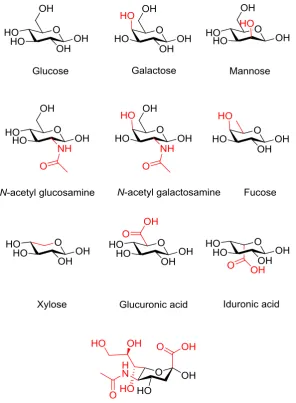
The detection and quantification of bacterial species is thus of great importance; microarray technology can be used to probe the mechanisms of bacterial adhesion and aid both diagnostics and the development of new treatments, Figure
8 quickly and easily obtained then the prevalence of unnecessary antibiotic prescribing, one of the causes of increased antibiotic resistance, can be reduced.
Figure 1.4: Glycoarray coated with mannose, glucose, N-Acetylglucosamine, galactose and
fucose. Labelled E. coli are seen to bind only to the mannose coated regions, due to the presence
of a mannose specific receptor protein (FimH) on their surface. Such systems can be used as diagnostic tools for the detection of pathogens. Taken from the work of M. D. Disney and P. H.
Seeberger16
A microarray is a solid substrate onto which compounds of interest are immobilised; they are used to assay large amounts of biological material in a high
throughput manner.17 The field of microarray technology began with antibody microarrays and quickly became applied to DNA. Today, however, there is great
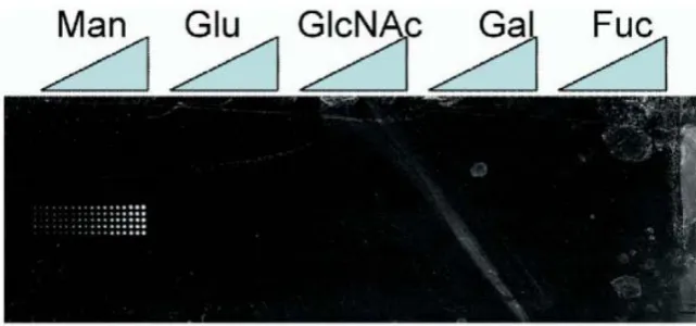
interest in the potential applications of carbohydrate microarrays, sometimes termed glycoarrays, which are surfaces displaying a large number of different carbohydrates, Figure 1.5. These arrays have the potential to not only shorten the timescales
involved in biochemical measurements, but also offer miniaturisation, which is as straight forward with solution studies. This is of particular importance when you
9 Carbohydrate arrays have transformed a number of medical and biological research areas, and can be considered as simplified biomimics of the cell glycocalyx.19
Figure 1.5: Current applications of carbohydrate microarrays, adapted from the work of N.
Laurent, J. Voglmeir and S. L. Flitsch18
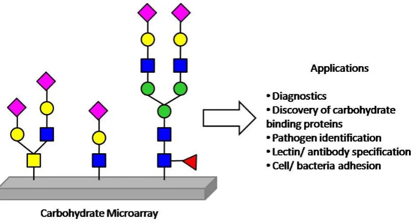
The immobilisation of the carbohydrates onto the array surface is critical to
the success of the technology. Broadly speaking, the immobilisation techniques can be categorised into covalent bonding or non-covalent (physical) adsorption. Each
category can be further divided into site specific (regioselective) and site non-specific, with respect to the attachment of the glycan on the surface, Figure 1.6.18 Due to non-covalent immobilisations relying on the glycans adhering to the surfaces
typically via hydrogen bonds, van der Waals interactions or other non-covalent interactions, a large contact area must be available. Therefore the glycans must be
10 coating22 to adhere polysaccharides in a non-site-specific fashion, or streptavidin-coated surfaces for adhering biotin conjugated glycans.23 The simplest covalent
immobilisations involve the attachment of free glycans onto boronic acid,24 phthalimide25 or azidoaryl26 coated surfaces in a non-site-specific fashion.
Techniques for the site-specific covalent attachment of the glycans have been the most extensively developed and there are numerous examples within the literature. Typically, modified sugars are required to bind to the surfaces, for example
homobifunctional disuccinimidyl functionalised glass requires ethanolamine functionalised sugars for binding.16
The use of covalent, orthogonal linkers is highly advantageous and they are widely employed,18 including by the Consortium for Functional Glycomics (CFG),27 which employs the amino linkers to react with succinimidyl ester glass slides. The
latest version of the CFG array system (version 5.2, 2012)28 employs 20 different spacer arms, ranging from simple Sp0 linkers, comprised of -CH2CH2NH2, to peptide
linkers, such as Sp24 and Sp25 (lysine-valine-alanine-asparagine-lysine-threonine and valine-alanine-asparagine-lysine respectively).16 The use of linkers in protein-carbohydrate binding systems allows controlled access to the binding pocket and can be used to improve selectivity. “Click” chemistry inspired routes have also been
developed, utilising alkyne or azido- sugars with their complementary surfaces.
More recently, thiol-ene type click reactions have gained attention in both their radical and nucleophilic (Michael addition) formats,29 see section 1.2.6. However, often glycans which have been synthesised de novo chemically or
chemo-enzymatically must be subjected to further modification and/or coupling in order to react with the desired array surface. In addition to the challenges associated with
11 interactions, this requirement for functionalised glycans is hindering progress towards a complete microarray technology; where in the future it may be possible to
present the entire glycome on one chip or on a series of chips.
The type of surface onto which the glycans are immobilised is also important. Gold has been used to support self-assembled monolayers of alkenethiols, onto
which monosaccharides can be immobilised,30, 31 but glass is most commonly used, including amino and epoxy silanised surfaces.32 However, the development of a
carbohydrate surface attachment that is compatible with a variety of surfaces would be highly desirable, allowing more extensive characterisation techniques to be
[image:44.595.132.502.389.690.2]utilised and also increasing the applications for the resulting microarrays.
Figure 1.6: Categories for the immobilisation of carbohydrates onto solid supports. Adapted
12 Recent progress in microarray technology has seen the introduction of arraying robots and printers, incorporating scanning devices for efficient monitoring
of detection signals. These methods can be divided into contact and non-contact printing. In contact printing, the glycans are printed onto the surface via the touch of
a steel pin which has been immersed in a glycan solution. Typically 0.5 nL of solution is printed in each spot. In non-contact printing, a piezoelectric printer delivers approximately 0.3 nL of glycan solution via a glass capillary and electrical
impulses, without touching the surface.33
As an alternative to carbohydrate microarrays, lectin microarrays have been
developed as a platform for glycan analysis. Instead of functionalising the surface with carbohydrates, lectins (or carbohydrate antibodies) are immobilised and fluorescently labelled glycoproteins are added. This method is being introduced as an
alternative to conventional glycan analytical techniques, such as mass spectrometry or liquid chromatography, because it does not require removal of the glycan from the
core protein prior to analysing. It enables direct analysis of crude glycoprotein containing samples; however it is not quantitative and is best suited to comparative studies such as differential profiling.34
In addition to the immobilisation of the carbohydrates, the elucidation with biological material can also pose challenges. Typically, fluorescently-labelled
proteins are added in order to assess binding, however, the isolation and labelling of proteins often proves to be challenging and it would be preferable to instead incubate the functionalised slides with whole bacteria. This can create the problem of
13 aggregates and continues, if the conditions are favourable, with the growth and division of the adhered cells. The resulting micro-colonies have both advantageous
applications (e.g. waste water treatment) but also pose serious disadvantages,35 as in this case where they will reduce the resolution of the assay and give rise to false
positive results. A non-fouling or hydrophilic surface could circumvent this problem, by resisting the adhesion of the proteins, bacteria and cells. The development of glass-based carbohydrate microarrays with high carbohydrate-spotting density and a
protein-resistant surface (Figure 1.7) has the potential to significantly improve this technology. It is proposed that this can be achieved using linkers composed of polymers of oligo(ethyleneglycol) or N-isopropylacrylamide, which possess both
protein resistant36, 37 and stimuli-responsive38 properties, as explained in section 1.2.5 Many polymers have been shown to exhibit attributes that are desirable for
[image:46.595.238.422.506.654.2]biomedical applications, such as antifouling properties,39 making them suitable for many array applications, but the synthesis of well defined, reproducible polymers is crucial to the success of these systems, requiring precision polymerisation methods.
Figure 1.7: Protein resistant surfaces are used to reduce non-specific binding and give higher
14
1.2.
Polymerisations
1.2.1. Controlled Radical Polymerisation Techniques
In order for polymeric species to be useful in biological and analytical applications, it has been shown that it is very important to exercise control over their properties, namely the molecular weight, dispersity and architecture. This allows the
fabrication of systems which are defined and reproducible.41 Much of the recent development in the field of polymer chemistry has focused on these challenges and several innovative techniques for producing highly defined polymers, generally
referred to as controlled radical polymerisations (CRP), have been developed. These techniques build on the advantages of conventional free radical polymerisation
(FRP), with its benefit of not requiring stringent process conditions and its ability to be used for the (co)polymerisation of a wide range of vinyl monomers, however they offer far greater control over the resulting polymer chains.42 Generally the CRP
methods work by extending the lifetime of the propagating chains. This is achieved by establishing a dynamic equilibrium between a minimal concentration of active
radicals (propagating chains) and a predominant amount of dormant chains in the system, therefore reducing the occurrence of termination processes. Due to chains remaining as dormant species, where they are capable of reactivation and chain extension, rather than terminating, CRP can be classed as a “living” system.43
The basic mechanistic principle for this process is seen in Figure 1.8.
15 Nitroxide-mediated polymerisation (NMP),44 atom transfer radical polymerisation (ATRP)45 and reversible addition-fragmentation chain transfer
(RAFT)46 polymerisation are the three most popular CRP processes in use today. In NMP, the control is achieved through the addition of an alkoxyamine initiator, which
results in the reversible end-capping of growing polymer chains with a nitroxide species.47, 48 ATRP is a metal-mediated polymerisation technique, where the presence of a transition metal catalyst, typically copper, determines the equilibrium
between the active and dormant species.45, 49
1.2.2. RAFT Polymerisation
This work has made use of RAFT polymerisation, which was first reported by the CSIRO group back in 1998.46 There are many advantages to this technique, it
is considered to be one of the most versatile CRP techniques available; it can tolerate a wide range of monomers, solvents and initiators, exhibits good end group fidelity
and can produce polymers and copolymers with narrow dispersity, often to high conversion.50 The seminal RAFT polymerisation paper described the polymerisation of a variety of (meth)acrylates, styrenic and acid (salt) monomers in a free radical
polymerisation process, but with the key addition of a small amount of a thiocarbonoylthio-containing compound as a chain transfer agent (CTA), Figure 1.9.
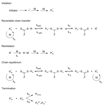
The addition of the CTA allowed control over the free radical process and the production of polymers with dispersities typically less than 1.2. This is achieved through the rapid equilibrium between active and dormant forms of the propagating
radical species; therefore all chains will grow and will have an equal chance of growth. The molecular weight increases linearly with conversion and the molecular
16 thiocarbonylthio group attached to an R and Z group, Figure 1.9. Through modifications to the free radical leaving group (R) and the activation/deactivation of
the thiocarbonyl double bonds, by altering the Z component, a wide range of monomer species can be accessed.
Figure 1.9: CTA structure categories with the type of monomer typically used for each listed below in italics
In a conventional radical polymerisation process, the radicals are generated (initiation), the individual chains then grow for 5-10 s (propagation) before undergoing combination or disproportination (termination). RAFT polymerisation,
Figure 1.10, possesses the characteristics of a living polymerisation. The chains all begin to grow at the start of the polymerisation and continue to grow until the
monomer is consumed. The mechanism consists of five key events. The first stage (initiation) and final stage (termination) are the same as in the conventional radical process, however the stages in between differ and it is in these steps that the control
over the process occurs.51 Following initiation an initial equilibrium is established; the propagating radical (Pn˙) adds to the CTA to form an intermediate radical
species. This radical then fragments into a polymer adduct of the CTA and a new radical (R˙), which can react with the monomer to form a new propagating radical
17 (Pm˙) can add to the CTA, releasing the other radical (Pn˙). Due to the rapid
equilibrium between the active propagating radical species (Pn˙and Pm˙) and the CTA
polymer adduct, there is equal probability of growth for all chains and hence control over the resulting polymer chains is possible. As it is the R group that initiates the
polymer chain growth in the initial equilibrium step, this radical leaving group should be a better leaving group then the propagating radical (Pn˙) and be sufficiently
reactive to re-initiate the polymerisation. It is also important for the Z group to
[image:50.595.154.496.331.693.2]activate the C=S bond to the addition of the radical and then stabilise the resulting adduct.
Figure 1.10: The proposed mechanism of RAFT polymerisation, adapted from the work of G.
18 Although unrelated to the requirements of this work, it is also important to note that RAFT polymerisation has been successfully used to synthesise more
complex architectures, including block copolymers, stars, hyperbranched polymers and hybrid nanoparticles, showing the high levels of control that are possible.52
1.2.3. End Group Modification of RAFT Polymers
A major advantage of the RAFT technique is that the nature of the CTA leads
to functional groups at both ends of the polymer chain. Both the α-end and/or ω-end can be modified, without the need for further manipulation, by incorporating
appropriate functionality into the RAFT agent at the R or Z position (Figure 1.11), making the technique very versatile and suitable for a wide range of applications.50 Incorporation of functionality into the R group of the initiating species can produce,
for example, carboxylic acid,53 peptide54 and lipid α-end-functionalised polymers.55
Figure 1.11: RAFT agent and resulting RAFT polymer, showing the α-end (R) and ω-end (Z)
The ability to functionalise the α-end of the polymer during RAFT
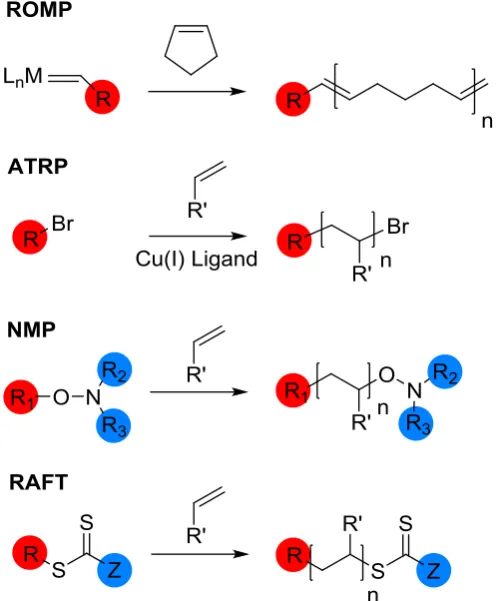
polymerisation is also seen in other types of CRP, such as ring opening metathesis polymerisation (ROMP) and atom transfer radical polymerization (ATRP), but a novel feature of RAFT is the ability to also functionalise the ω-end of the chain. This
is possible due to the presence of the thiocarbonate, which can be modified, or removed, post-polymerisation.50 Although nitroxide mediated polymerization
19 peroxide initiator and the R2 and R3 are part of the TEMPO radical structure, so the options for varying the groups are limited, Figure 1.12.
Most useful to this project is the conversion of the thiocarbonylthio group to a thiol end group, which can then react with a gold surface or an alkene functional group. Literature techniques for this process involve reacting with excess amine to
act as a nucleophile,56 or addition of a reducing agent such as PBu357 or tris(2-carboxyethyl)phosphine (TCEP).58 The reaction of thiol-terminated RAFT polymers
[image:52.595.203.452.325.626.2]with gold has been reported, often to stabilise metal nanoparticles.59,60
Figure 1.12: Location of functional groups introduced by the initiator/CTA in polymers produced by ROMP, ATRP, NMP and RAFT. ROMP (excluding the functionality of the double
20 Additionally, work into the synthesis of glycopolymers has been successful through highly efficient post-polymerisation alkyne-azide cycloaddition reactions,
allowing the creation of libraries of glycopolymers.61, 62 Glycopolymers are synthetic polymers containing carbohydrate pendant or terminal groups along the backbone.63
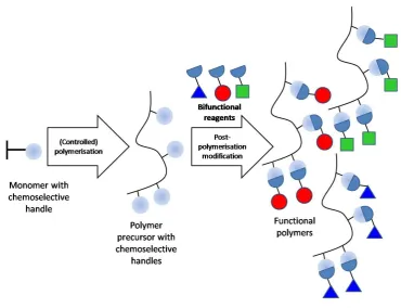
The presence of multiple sugar units along each polymer chain allows them to bind lectins in a multivalent fashion and therefore benefit from the cluster glycoside effect.11 They can be synthesised using post-polymerisation modification processes,
Figure 1.13. Monomers bearing functional groups of interest (chemoselective handles) are polymerised to create a library of polymer precursors, still retaining their chemoselective handles. These polymers can then be modified with
bifunctional reagents to produce the desired functional polymers. This post-polymerisation modification allows access to functionality which would not have
been compatible with the polymerisation process if included within the monomer. Also, due to producing a stock of polymer precursors from the same initial polymerisation process, there is the ability to create differently modified polymers
with the same molecular weight and dispersity. The creation of these libraries of different glycopolymers, but with the same or very similar molecular weights and
molecular weight distributions are very useful in order to probe structure-property relationships.62
RAFT polymerisation has been used to synthesise poly(pentafluorophenyl methacrylate) (pPFMA) backbones, which are then reactive to further modification. As a modification to this process, a tandem post-polymerisation modification method
has been developed. The pPFMA scaffold can be functionalised with allylamine, resulting in pendant alkene functionality, and then subjected to thiol-ene “click”
21 Alternatively, a 3-step tandem post-polymerisation methodology can be used to synthesise glycopolymers with secondary binding motifs, which mimic glycan
[image:54.595.141.512.164.448.2]branching.65
Figure 1.13: The process of creating functional polymers using a two-step post-polymerisation modification process
1.2.4. Characterisation of Polymers
Polymers, can be characterised by nuclear magnetic resonance (NMR)
spectroscopy and proton NMR spectroscopy can be used to follow a polymerisation reaction through the disappearance of characteristic monomer peaks or the
appearance of polymer product peaks. Size exclusion chromatography (SEC), a technique established particularly for the characterisation of polymeric species, can be used alongside NMR spectroscopic analysis. In SEC, the polymer chains are
22 porous cross-linked polystyrene beads. As the polymer solution travels through the column the smaller macromolecules permeate the pores in the beads and take a long
time to be eluted from the end of the column. Conversely, the larger macromolecules are unable to enter the pores and thus they quickly pass through the column. The
elution of the sample from the column is monitored using an ultraviolet (UV) detector or by monitoring the light scattering, viscosity or refractive index of the solution. By comparing the data to known standards, the number average molecular
weight (Mn) and weight average molecular weight (Mw) for the polymer can be calculated.
1.2.5. Thermally-Responsive Materials
Polymers can be designed to change through their responsiveness to one or
more stimuli, such as temperature, pH, light, electrical and magnetic fields and ionic strength. This particular class of polymers are termed “stimuli-responsive” or
“smart”, indicating that they undergo a significant structural change in response to an
external stimulus. Typical polymer responses are changes in shape, surface characteristics or solubility. A particularly useful aspect of these materials is that a
significant change can be induced through only a small stimulus, i.e. the response is non-linear.66 The bulk response of the polymer is usually due to multiple small
co-operative interactions, which when summed over the whole polymer result in a large structural change. Highly directional hydrogen bonding, although weak in nature, plays a key role in these switching processes, particularly for polymer systems where