University of Warwick institutional repository: http://go.warwick.ac.uk/wrap A Thesis Submitted for the Degree of EngD at the University of Warwick
http://go.warwick.ac.uk/wrap/39025
This thesis is made available online and is protected by original copyright. Please scroll down to view the document itself.
The Use of Concurrent Engineering Methodologies
Achieving World Class Product Development Performancein the Automobile Industry
Report 8 of 8
Executive Summary
T A Leverton, Bsc (Hons), MBA, CEng, MIMechE of Rover Group Limited
in partial fulfilment of the requirements for the award of the degree of
Engineering Doctorate
Department of Engineering University of Warwick
,
BEST COpy
..
, . AVAILABLE
©
Rover Group Ltd. 1998All rights reserved. No part of this publication may be reproduced, stored in a retrieval system, or transmitted in any form or means without the permission of the Issuers.
Issued by:
Ti mothy A Leverton Product Director
Design and Engineering Rover Group Ltd.
Gaydon
Report 8: Executi'.'e Summary
Table of Contents
• Abstract
• List of Illustrations • List of Tables • Glossary of Terms
Introduction to the Executive Summary
SECTION 1: The Background to The Research
1.
Introduction to the Research Project
2. The Main Themes in the Research
2.1 Concurrent Engineering
2.2 Metrics for Product Development Performance 2.3 The Literature View of Best Practice
2.4 Benchmarking
2.5 Strategic Choices of Automobile Manufacturers 2.6 Product Development as Information Processing
3. The Structure of the Research Portfolio
SECTION 2: The Research
4. The Basis of the Rover Body and Pressings Case Study
5. The RPB Hypotheses
6. A Product Development Strategy for Rover Body and Pressings
6.1 Summary of World Class Benchmarks 6.2 Results of Causal Analysis
6.3 Strategic Targets
6.4 A Npw Model for Body and Tool Development 6.5 Chdnge Plan Content
-rilt' USt' of Concurrent f ngineering "'lt~thodologies
Page
1 3 3 4 5 6 6 8 13 15 17 17 18 18 ~O 22Report 8: Executive Summary
7. Manufacturing for Design
7.1 The Creation of Focused Toolrooms 7.2 Change Plan Implementation
7.3 Rover Group Project Commitments
8. Engineering Design Methodology
8.1 The Role of Information Technology in Design Methodology 8.2 Human Resource Issues and Engineering Design Methodology 8.3 Scope for Innovation
8.4 Metal Forming Technology 8.5 Conclusions from the Research
8.6 Proposed New Engineering Methodology 8.7 Change Implementation
II
28
28 33 35
38
39 40
42 44 45 46
9.
The Effectiveness of the New Product Development Strategy at RBP
49
9.1 Achievement of Strategic Targets 9.2 Comparison of RBP to Worlds Best
10.
The Reengineering of Product Development at Rover Group
SECTION 3: Summary
11. Demonstration of Innovation
12. Conclusions
13. Proposals for Further Work
•
Appendices
•
References
1 he U'it' of Concurrent Engineering ,\fpthodo/ogie5
49 54
55
60
63
65
-Report 8: Executive Summary
ABSTRACT
This research project is about product development strategy and practice in the automobile industry. Specifically, it concerns the transformation of Rover Group body and tool development capability over four years from 1993 to 1997.
A single Rover Body and Pressings organisation was created in 1991. It
encompassed the functions of Body Engineering, Press Tool Engineering, and Press Tool Manufacturing. As Engineering Director the Author had the
opportunity to directly influence a significant portion of the body product creation process.
At the start of the research period the product development performance of
Rover Body and Pressings was weak. Major investments in new press equipment could not depend on in-house die technology. Quality and cost delivery
incurred customer dissatisfaction.
Resulting from the research are three innovations:
The Engineering Quality Assurance Procedure was implemented as a disciplined stage/gate quality management system.
A focused manufacturing strategy was implemented for die manufacturing based on die size.
A new engineering design methodology was established utilising the
scientific principles of metal forming technology as an integrated element in the design process.
These innovations were applied within the strategic framework of a new model describing a system view of the product creation process for body, at enterprise level.
The new product development process strategy was partially applied to two new vehicle programmes. One vehicle has since been initiated and delivered from within the new framework.
Strategic targets were defined for product development at Rover Body and Pressings covering product quality, development lead time, press tool cost and programme financial budget. The targets for quality and lead time were met during the research period. Although substantial progress is evident in physical performance the targets for press tool cost and programme budget were not met.
The major elements of the product development strategy applied in this research remain in place. The transfer of the strategic model of concurrent engineering to a wider context was demonstrated by applying it as part of the Rover Group product development reengineering project.
---- - --
-III
Report 8: Executive Summary
The leadership, and majority of intellectual development of the strategic
innovations described in the research was solely the work of the Author while Engineering Director of Rover Body and Pressings. Supporting resources were used, under the direct leadership of the Author. Elements directly contributed by others have been dearly referenced.
.
IVReport 8: Executive Summary
List of Illustrations
Figure 8.1 8.2 8.3
8.4
8.5 8.68.7
8.8
8.9 8.10 8.11 8.12 8.13 8.14 8.15 8.16 8.17 8.18 8.19 8.20 8.21 8.22 8.23 8.24 8.25 8.26 8.27 8.28 8.29 8.30 PageMetrics for the Evaluation of Product Development Performance in the
Automobile Industry 4
Product Development Strategic Thrusts of Automobile Manufacturers / Phase Diagram of the Product Creation Process for an Automobile Body 13
Rover Group Product Creation Process for Body 14
Coverage of Hypotheses by Research Portfolio Submission 16 A New Process Flow Model of Body and Tool Engineering 20 Completed Process Model of Body and Tool Engineering 21 The linkage of change plan content to the RBP product development strategy
model 22
The high level process flow of EQAP 23
Links between change plan action thrusts and root cause areas 25 Change Plan Goals and Milestones for RBP Engineering 1992-96 26 Organisation Template for Focus Tool Manufacturing Units 27 Summary profit and loss account templates for the proposed RBPE focus tool
manufacturing implementation 29
High Level Die Manufacturing Process Flow, including "M" Event
Descriptions 30
Implementation of an Information Structure for effective Manufacturing
Planning and Control in RBPE 31
Overview of the Focus Toolrooms Change Plan 34
The "Design Based Approach" to Body Panel and Metal Forming Process
Engineering 41
Example results report from FAST_3D for the CB40 Bonnet Outer Panel 42 A proposed new engineering methodology for Body and Tool Engineering 45 Training Strategy for Metal Forming Technology in RBP 46
Strategic CAD system architecture for RBPE 47
Average OEE Performance week 42/97 to week 8/98 49
Actual Dates Achieved on the on the R3 3 Door Bodyside Programme 50 Die Engineering and Manufacturing Lead Time Results 51
Absolute Bodyside Die Costs 1991 to 1998 52
Performance to Programme Financial Budget ~3
RBP Performance compared to World's Best September 1997 S4
Organisation Development under Reengineering ~~
The Composition of Rover's Future Product Development Process
Sh
The Configuration of Product Development Process in a Reengineered
Environment 57
.
Report B: Executive Summary VI
List of Tables
Table
Page
8.1 Summary of RBP Performance Metrics 17
8.2 Throughput and Manning Summary before, and after, focus Toolroom
Implementation 28
8.3 Sourcing evaluation of Core and Non-core elements of Large press tool
manufacture 32
8.4 Summary of Issues arising from the literature on design 38 8.5 Case data showing benefits of the Fti, RBP Engineering approach 43 8.6 RBP Component Supply Quality Measures 1993 vs 1997 49 8.7 Actual Dates Achieved on the on the R3 3 Door Bodyside Programme 52 8.8 Analogies in Product Development Strategy between Analogies in
Product Development Strategy between 58
Glossary of Terms
AOK After OK Panel
BOK Before OK Panel
CAD
Computer Aided DesignCADDSS
CAD software trade nameCAE
Computer Aided EngineeringCAM
Computer Aided ManufacturingCATIA
CAD software trade nameCV
Computervision Corp.CB40
Land Rover FreelanderDOl
1st Stage Engineering PrototypeD02
2nd Stage Engineering PrototypeDl
Validation BuildE 1 ,E2,E3
EQAP Engineering EventsEQAP
Engineering Quality AssuranceProcedure
FEA
Finite Element AnalysisFLD
Forming Limit DiagramFTi
Forming Technologies Inc.H H-R
Rover 400 96MYIT
Information TechnologyM
1,M2
EQAP Die Manfg. EventsMFE
Metal Forming EngineeringMFT
Metal Forming TechnologyNC
Numerical ControlNCBS
New Car Buyers SurveyOEM
Original Equipment ManufacturerPl,P2
EQAP Productionisation EventsP38A
New Range RoverPMP
Rover Group ProjectManagement Policy
PR3 MGF
QP
Quality ProvingQZ
BMW Quality Rating SystemR3 Rover 200 96MY
RBP
Rover Body and PressingsRBPE
RBP EngineeringSID
Static/Dynamic BalanceSFDC
Shop Floor Data CollectionSOP
Startof
ProductionTl,T2,T3
EQAP Die Tryout EventsTri-Axis
Transfer PressReport 8: Executive Summary
- - -
-SECTION
1:
The Background
to the Research Project
- - -_.-. _.-._--
- - - -
- - _ .. -Report 8: Executive Summary
1. I
ntroduction to the Research Project
This research project is about product development strategy and practice in the
automobile industry. Specifically, it concerns the transformation of Rover Group
body and press tool development capability over four years from 1993 to 1997.
The scope and content of the research are strategic. The project ai med to
identify, and prove, a strategic framework for effective product development
performance. As such, the range of subjects covered reflects the entire span of
functional del ivery processes embraced by the product creation
system
of a business.In the 1990's, a collection of tools, techniques, and practices has become known
as concurrent engineering. It is a basic premise of this research project that
concurrent engineering is highly relevant to improving the enterprise wide
product creation system.
The emergence of the Rover Body and Pressings business unit provided the
opportunity to conduct this research. The placing of the body product
engineering, press tool engineering, and press tool manufacturing operations of
Rover Group into one organisational unit was a bold and unique step in 1991.
This research portfolio documents how the problem of improving the weak
performance of Rover Body and Pressings product development process was
undertaken.
The research started out by considering product development effectiveness as a
generic problem in the context of the automobile industry. A framework for the
evaluation of product development performance was used to derive general
hypotheses regarding the basis for effective practice.
1
Report 8: Executive Summary
These general hypotheses were appl ied to the specific context of body and tool
development. Following diagnostic research an innovative model of body and
tool engineering was proposed. The majority of the research portfolio covers the
development, implementation, and evaluation of specific innovations required to
realise this model.
Through the research period the initial ideas behind the research were refined
and clarified. The emphasis in the research changed from the pursuit of lead
time reduction, per se, to the knowledge intensification of the engineering
design phase of development, supported by appropriate technology delivery
capability.
The transfer of the innovations in the Rover Body and Pressings case was
demonstrated by applying them to the new product introduction process of the
Rover Group as a whole.
2
)
Report 8: Executive Summary
2.
The Main Themes in the Research
2.1 Concurrent Engineering
Up unti I the start of the 1990's sequential models of product development had formed the basis of training of engineers and managers in the western world (Ward et al). As the 1990's have progressed this paradigm has been replaced with a new one based on concurrent design of product and process, and
integrating life cycle criteria of the product in the development process (de Graaf 1996).
The term "Concurrent Engineering" was first coined in the Institute for Defence Analysis report R-338 to explain the systematic method of product and process design (Winner et al 1988).
To improve the efficiency of the product development process it is necessary to
integrate the activities of the major business functions of a company, utilising changes in people practices, organisation, business processes, and information technology. Cleetus (1992) provided an extended definition of concurrent
engineering that addresses this context:
"Concurrent Engineering is a systematic approach to the integrated and
concurrent development of a product and its related processes, that emphasises response to customer expectations and embodies team values of co-operation, trust, and sharing in such a manner that decision making proceeds with large intervals of parallel working by alilife-cycle perspectives, synchronised by comparatively brief exchanges to produce consensus."
It is in this wider corporate context of concurrent engineering that the links are to
be found between the product development process itself, and the systemic
attributes of the corporations ability to bring new product to market.
3
Report 8: Executive Summary
2.2 Metrics for Product Development Performance
Development Total Product
Productivity Development cost per unit' (£').---l~"""1 ___ JD Powers (FauIlsl100 vehs.) Quality
Chrysler 344 Toyota
Total development cost ( Warranty (Faulslvehs)
Audi 75 Lexus
Total engineering man hours(x10 2 " RectifICation % ._____ Japanese --1~-~-===~~E:==--J'---~---.Jrra:tJ¥O~ta. 1.6 ,
--.---.
Changeover time fo new models (weeks) 2
Honda
Manufacturing Operating Performance
Material margin % Ford
Direct labour (hours/unit)
Nissan UK
1
First Prototype to SOP (mitis) Concept to SOP r~W?srchrysler
[image:16.671.88.603.69.482.2]Toyota Development Lead Time
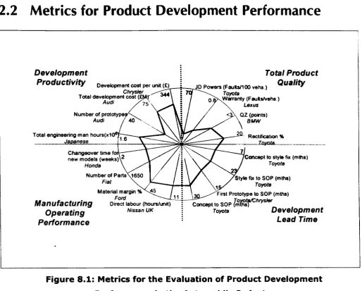
Figure 8.1: Metrics for the Evaluation of Product Development
Performance in the Automobile Industry
(references in Appendix 1)
Four dimensions of product development performance were identified to
distinguish competitive performance, and the practice of concurrent engineering.
Total Product Quality - reflecting both the functional and design performance of
the product, and the consistent achievement of the engineering intent from the
manufacturing process.
Development Lead Time - elapsed time from project approval to market
presentation of the product.
Manufacturing Operating Performance - excellent manufacturing performance is a
pre -requisite for concurrent engineering practice.
Development Productivity - the capacity to bring new product to market.
4
- - - -
Report 8: Executive Summary
2.3 The Literature View of Best Practice
In their research on product development in the automobile industry, during the
late 1980's, Clark and Fujimoto (1991) concluded that coherence in
development practice and the factors of competitive success for a firm, is a
determinant of high development performance (Clark & Fujimoto 1989a). They identified four themes, characterising high performing organisations:
i. Superior performance in time, productivity and quality; high performers
pursued excellence in all three dimensions simultaneously (Stalk & Hout 1991,
McGrath 1997).
ii. Integration in the development process; effectiveness in inter-functional
working, and problem solving (Womack et al 1990, Clark & Fujimoto 1989b).
iii. Integrating customer and product; specific competencies in realising customer
needs into deliverable product solutions (Pugh 1996, Clausing 1993).
iv. Manufacturing for design; transfer of manufacturing management know how
into the management of development, and specific competencies in
manufacturing processes directly supporting development, e.g. prototyping and
die making (Clark & Fujimoto 1991, Whitney 1995).
Some researchers favour managerial explanations supporting examples of best
practice based on teamworking, and organisational strategies (e.g. Clark and
Fujimoto 1991, Nobeoka 1995, Scott 1994). Others explain best practice in
terms of technology strategy (e.g. Whitney 1995, Carter
&
Baker 1991).5
Report 8: Executive Summary
2.4 Benchmarking
As a by-product of Rover's recent business history the Author has had the
privilege of developing close working relationships with Honda Motor
Company, of Japan, and since 1994 BMW AG, of Bavaria.
Unique levels of access to two of the three most globally competitive automobile
manufacturers in the world has strongly flavoured the shape of this research
project.
2.5 Strategic Choices of Automobile Manufacturers
There are common themes of strategic development amongst competing
automobile manufacturers, for example organisational development, CAD
technology, and lead time reduction. However, there is no absolute consistent
pattern of pol i~y choice.
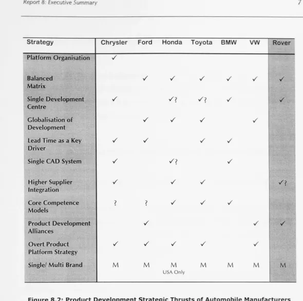
Figure 8.2 summarises the key strategies currently being pursued.
Emerging factors are product structure and platform strategy, globalisation of
development, and changes in the relationship to suppliers in the development
process.
6
Report 8: Executive Summary
I
Strategy Chrysler Ford Honda Toyota BMW VW Rover
Platform Organisation ./
Balanced ./ ./ ./ ./ ./ ./
Matrix
Single Development ./
./?
./?
./ ./Centre
Globalisation of ./ ./ ./ ./
Development
lead Time as a Key ./ ../ ../ ./
Driver
Single CAD System ../
./?
./Higher Supplier ../ ./ ../
./?
Integration
Core Competence
?
?
./ ./ ./Models
Product Development ../ ./ ./
Alliances
Overt Product ../ ../ ./ ../ ./
Platform Strategy
Single! Multi Brand M M M M M M M
USA Only
[image:19.671.24.615.21.608.2]".
Figure 8.2: Product Development Strategic Thrusts of Automobile Manufacturers
(for references please refer to Appendix 2)
2.6 Product Development as Information Processing
Th m nagement of the flow of information has been a recurring th m in thi
r r h project. The view of product development as n information ro In
m b d on the f ct th t while project content u uall diff r fr m
t, th
10
m nt ro r oft n r r1 ).
111
r
n urr nt n In nn \I th d I T \ LReport 8: Executive Summary
3.
The Structure of the Research Portfolio
A review of the literature and product development strategy in the automobile industry revealed that all manufacturers are pursuing the goals and processes associated with concurrent engineering. Five general hypotheses were derived. The hypotheses were tested in two case studies.
Case 1: Body and Tool Development at Rover Body and Pressings
The first case study represents the major portion of the research project portfolio.
The body and die development process is a core element in the product
development process of new vehicles (Clark
&
Fujimoto 1991, Ward et al 1995).It is a subset of the total vehicle development process. It carries a lower product and process complexity than a complete motor car.
The Author was appointed as the first Engineering Director of Rover Body and Pressings, a newly created business unit in Rover Group, in February 1991.
Case 2: New Product Introduction at Rover Group
Following the acquisition of Rover by BMW AG, a fundamental restructuring of Rover's product development operations took place in May 1996. In the new,
autonomous, Design and Engineering function the Author was appointed
Product Director, Luxury and Full Size 4x4, and Champion for the
"Re-engineering" of product development in Rover Group.
A brief description of each portfolio report is given belo\\.
8
----~--- -
Report 8: Executive Summary
Report 1:
Abstract
A brief summary of the whole research project
Report 2: The Practice of Concurrent Engineering
This report reviews the status of practice in product development, and
concurrent engineering, within the world automobile industry. It carries the main literature survey carried out for the research project. Definitions for
product development and concurrent engineering are clarified, and the basis for measurement of product development performance is established.
From the I iterature survey general hypotheses are stated. A description of the overall structure of the research project concludes the report.
Report 3: A Product Development Strategy for Rover Body and
Pressings.
This report deals with the derivation of a new product development strategy for
Rover Body and Pressings. The generic hypotheses from report 2 are applied to the specific case of Rover Body and Pressings. These are to be tested through
the implementation of a new strategic framework for body and tool engineering development.
A detailed calibration is made of the baseline performance at the start of the
case. The results of a detailed causal analysis are used to identify the root cause
factors for poor performance.
A Ilt'W model of body and tool development is presented which gives
precedence to the specification of high quality metal forming proces"t'S.
9
--- - - -
Report 8: Executive Summary
Concurrent engineering methods are to be used to create the metal forming process, and effective delivery processes are to be established to fulfil the process specification exactly. This model is the basis of the new product development strategy.
An overall change plan is the basis for implementation of the new model. An Engineering Quality Assurance Procedure is proposed to act as a stage gate process for management of the product development process, and is supported by other enabling actions.
Report 4: "Manufacturing for Design"; Towards World Class Die
Manufacturing
This report covers the development and implementation of strategic changes needed to improve the operational performance of Tool Manufacturing department of the Rover Body and Pressings Engineering function.
The results of diagnostic research are presented. These include an operational dud it, competitive benchmarking, and the identification of useful principles in
the literature.
Strategic targets for tool manufacture are defined. The diagnostic results are analysed to determine the appropriate basis for action planning, and policy
choices with respect to technology, operating practices, and manufacturing
strategy.
---.----10
Report 8: Executive Summary
Report 5: Choice of Engineering Design Methodology.
This report is concerned with the selection of an engineering design
methodology to satisfy the objectives of the new product development strategy
of Rover Body and Pressings.
The basis for choosing the configuration of the engineering design process is
described. Observations of the relative information flow between the vehicle
development programme and the body development programme are made.
Trends in design methodology within Body Engineering are described which
exploit the increasing use of engineering analysis as part of design synthesis.
It is concluded that Tool Engineering can be developed to emulate the trend in
Body Engineering by using metal forming technology. A new engineering design
methodology is described in the form of process steps with specific goals and
responsibi I ities.
Report 6: Review of the Effectiveness of the New RBP Product
Development strategy.
This report presents the results achieved following the implementation of the
innovations to the Rover Body and Pressings product development process. The
results are taken from late 1997 to capture the data from the Land Rover
Freelander project, the first vehicle project to be initiated and delivered since the
changes were made.
The results are presented against each of the four strategic targets for product
development at RBP set out in portfolio report 3. The changes in overall product
development performance are compared to the baseline performance at the start
of the research period.
11
Report 8: Executive Summary
Report 7:
The Reengineering of Product Development at Rover
Group
The purpose of this report is to demonstrate that the innovations applied at Rover
Body and Pressings are transferable to a wider product development process
context.
The implementation of the reengineering project in Rover Group is described. A
process configuration for product development under a reengineering scenario is
derived. The main themes arising are analysed, and compared to those from the
Rover Body and Pressings case.
Report 8:
Executive Summary
An overview of the major elements of the research portfolio.
The Use of Concurrent Engineering Methodologies
Repon 8: E/fJ:ut/"r~ Summary
SECTION
2:
The Research
Report 8: Executive Summary
4.
The Basis of the Rover Body and
Pressings
Case Study
This case was concerned with the product creation process rele ant to the d i n
and development of automobile bodies, and the assemblie ,com on nt ,
manufacturing processes and tools which they comprise. The product cr tion
process of Rover Body and Pressings at the start of the ca e i ho n b
10
the phase diagram in figure 8.3.
PRODUCT DEVELOPMENT PROCESS DEVELOPMENT MANU A URE
Figure 8.3: Phase Diagram of the Product Creation Process for an Automobile Body
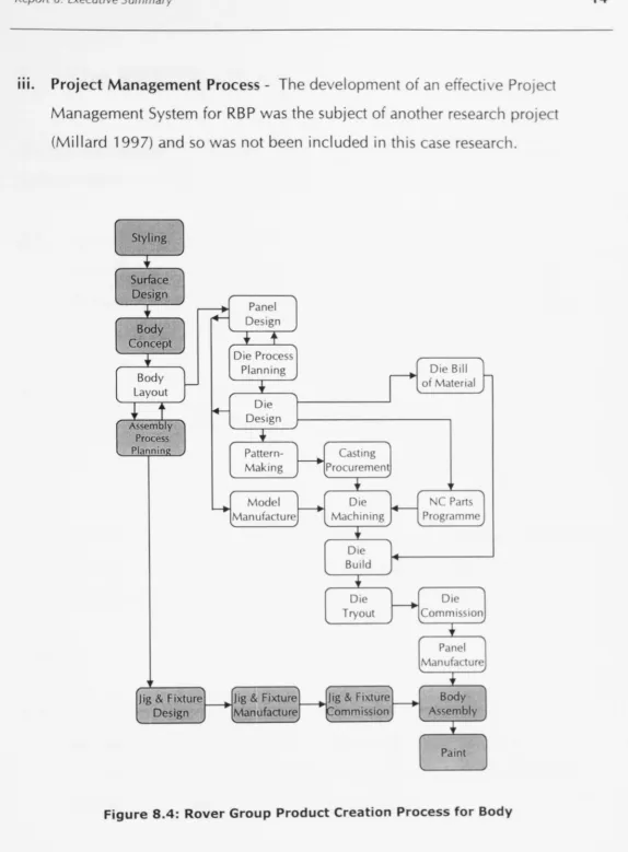
Figur 8.4 shows a high level view of the Rover Group pro uct cr tion pro for th car bodyshell. Each box identifies a key process step.
h r w r thr d I i mit tion of the ca e study.
I.
Proces es outside RBP responsibility
-
Th pro h In thb in fi ur 8.4 r Iud from th r r h of thi
II.
0 v
pment of Body
Sub-A embli
h ti\vith th lu
f
r m th I rn urr nl n In rin ,\ f )(11 1(1) I(
[image:26.671.44.631.128.975.2]Report 8: ExecutIVe Summary
III.
Project Management Process
-
The de elopment of an effecti e ProjectManagement System for RBP was the subject of another re earch proj ct
(Millard 1997) and so was not been included in this case re earch.
1 h U (I
Styling
..
Surface Design..
Body Concept..
Bodyf--Layout
+
t
Assembly Process PlanninR
Panel
+4 Design
•
t
Die Process
Planning
..
~ DeDie sign
..
Pattern
-Making
Di Bill
i1
of M t nalI-f - - - '
Casting ~Procurement
Mod I Die Part
---.jManufacturef---+l Machining I+--l Programme
..
Ole Build Ole Tryout Panel1M
nufacture..
Jig & Fixturer---+lJig & Fixture~Jig & F.bct~re~ BodyDesign Manufacture ~ommlsslon Assembly
[image:27.673.58.633.31.811.2]..
PaintFigure 8.4: Rover Group Product Creation Process for Body
n urr nt n In rtn I I (h dol
,-'
Report 8: Executive Summary
5.
The
RBP
Hypotheses
The following hypotheses were derived by applying the general hypotheses to the Rover Body and Pressi ngs case context.
5.1 That the four dimensions of world class automobile body and tool
development are Product Quality, the Cost of Press Tools, Press Shop
Operating Practice, and lead Time from exterior design freeze to start of series production.
5.2 Lead Time has the highest impact on the competitiveness of the automobile manufacturer.
and
5.3 That the foundation upon which World Class body and tool development
is built is the engineering excellence of the metal forming process
specification.
leading to
5.4 The creation of an organisation operating a new engineering
development methodology, which integrates the requirements and
constraints of the automobile design and metal forming science into the
specification of capable metal forming processes.
15
5.5 These processes are delivered to the press shop in a robust manner
through the appl ication of excellent project management, dnd sLlte of thf'
art press tooling technology.
Report 8: Executive Summary 16
Submission Hypothesis
5.1 5.2 15.3 15.4 5.5
! Report 3: A Product Development Strategy for
•
•
•
•
l
Rover Body and PressingsReport 4: Manufacturing for Design
•
Report 5: Choice of Engineering Design
•
Methodology
[image:29.671.40.640.24.886.2]Report 6: The Effectiveness of a new Product
•
•
Development Strategy at RBPFigure 8.5: Coverage of Hypotheses by Research Portfolio Submission
Report 8: Executtve Summary
6. A Product Development Strategy for RBP
6.1 Summary of World Class Performance
Metrics
Table 8.1 gives a 1993 summary of the selected metric for each of the
f
urdimensions of performance which comprised the e aluation model.
Metric
Product Quality
NCBS -Sturdiness of Body
- Body Workman hip
- Overall Quality Body Cosmetic Quality - QZ
Body Accura y
Component Supply Qual ity
Unplanned R tifi ation
Lead Time
L d Time ( lay fix to OP)
Programme level slippage
P n I Supply A hi
Press Tool Cost
P n i p r Body Tools per die set
Tool Co t Indi - Small - M dium - Larg
C ntract Performance Factor
Pre s Shop Performance
Overall Equipment Effectiveness Pr Utili tion - Tr n f r
- Tand m
Die Change Time - Transfer - Tandem
h t P r rt
Pr Run Length - Tr n fer
- land m
RBP
1993
8.00-8.63
7.54-7. 4 7.82-8.15
:::3.0
70% 5000 ppm
o
t 80 min .146
3 month 95% 380 3.5 100 100 100 1.2 to 1.5
:::40%
Benchmark
1993
>
.00>8. 0 > 8. 0
<0.5 0%+ <300 ppm
o
10o
100% 250 3.0 50 9 75 k ot Availabl >70% ~-- - - ' 80% 50% <5 min.3 to 5 hrs.
1500 5-8,000
5 00
80%
80%
<5 min. <20 min
< 2000
Table 8.1: Summary of RBP Performance Metrics
Ihell ')1 n u(('(llLn In (In th de /0 I(
1
Report 8: Executive Summary
6.2 Results of Causal Analysis
The following root cause areas were selected for as priorities for the change plan.
1. Quality Assurance Framework
2. Metal Forming Technology Competence
3. Skills and Knowledge Shortfall
4. Information Flow Integrity
5. Cross-Functional Integration
6. Press Tool Technology
7. Toolroom Operations Development
8. Integrated Scheduling Environment
6.3 Strategic Targets
6.3.1 Product Quality
Target:
Top quality component supply from transfer presses with RBPEmanufactured tooling.
When the £54M investment was made in two 5000 tonne transfer presses at
Swindon, RBP was dependent on Honda die technology to commission and
operate the presses. This target was defined to ensure that the technology
competencies associated with the entire manufacturing process chain for the
largest cosmetic stampings was consolidated in-house.
-18
Report 8: Executive Summary
6.3.2 Lead Time
Target: 80 weeks from style fix to QP panels.
This target was identified to ensure that a satisfactory information flow could
be
maintained within the vehicle development programme as a whole. In addition,
it was a strategic aim of RBP, at the start of the case, to be a recognised supplier
of press tools to Honda and this demanded a match to Honda's own lead times.
The metrics selected were body engineering release to parts off tools, and body
engineering release to start of vehicle production.
6.3.3 Press Tool Cost
Target: Press tool costs competitive with Japanese average die prices.
This target was defined to ensure that Rover Group did not incur a competitive
disadvantage by manufacturing dies in house, and to enable RBP to gain external
tooling contracts to fill open capacity resulting from Rover Groups long range
plan profile.
6.3.4 Programme
Target: Delivery to programme financial budget.
This target was defined to improve customer satisfaction, and to eliminate the
incidence of unplanned funding requirements.
19
Report 8: ExecutIve Summary
6.4 A New Process Model for Body and Tool
Development
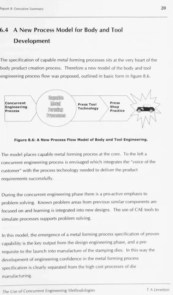
The specification of capable metal forming processes sits at the e he rt of th
body product creation process. Therefore a new model of the bod and tool
engineering process flow was proposed, outlined in basic form in figure 8.6.
Concurrent Engineering Process
Press Tool
Technology
Press
Shop
[image:33.671.67.632.0.965.2]Practice
Figure 8.6: A New Process Flow Model of Body and Tool Engineering.
The model places capable metal forming pro ess at th or . To th I ft
concurrent engineering process is envisaged which integr t
ustomer" with the process technology needed to deliver th produ t
requirements successfully.
of th
During th oncurr nt engineering phase there is a pro-activ mph to
probl m solving. Known problem areas from previous similar om n nt
fo u d on and learning is integrated into new designs. The us of A t 01 to
imul te processes supports problem sol ing.
In lhi mod m rg nce of met I forming pro i fi tion
f
ro noutput from th d Ign ngln n
r th un h into m nuf f th
nt f nn nfi n in th ro
-
p
ifi
c ti III rl m th hi h o t rm Iluf turin .
1 h ' U~ (I n urr nt n In (In T
Report 8: Executive Summary 21
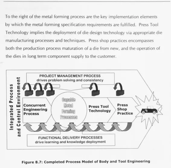
To the right of the metal forming process are the ke implementation element
by which the metal forming specification requirements are fulfilled. Pre Tool
Technology implies the deployment of die design technolog ia appropri
manufacturing processes and techniques. Press shop practice encompa
both the production process maturation of a die from ne ,and the op r tion of
the dies in long term component supply to the customer.
en en Q) (J 0
...
A. '1:1 Q)..
cu...
m Q)
-
C..
cQ) E c 0
...
> C W 0...
..
c0
u
'1:1
C
cu
PROJECT MANAGEMENT PROCESS drives problem solving and consistency
Concurrent En9,ineering Process
FUNCTIONAL DELIVERY PROCESSES drive learning and knowledge deployment
[image:34.673.53.620.53.610.2]Press Shop Practice
Figure 8.7: Completed Process Model of Body and Tool Engineering
Th import nee of knowledge capture in the developm nt ro
y pursuing a strategy of spe ialisation of people both in proc
To ompl ment this a project management proces is nee
fun tional integration, problem solving and con istent conform n
I r 0 nl
d
nd u t.
d
v lopm nt pro r quirem nt . An integr ted pro n m n m nlntr I n Ironm nt i n d to o-ordinat nd r gul t thi III
inf rm ti n n twork.
h
dill
h n in fi u r 8.7 n Inn , t l \I
f
rR
rB
nd
hi III I \th
rReport 8: Executive Summary
choice of specific actions and initiatives to implement RBP's product
development strategy.
6.5 Change Plan Content
Engineering Quality Assurance Procedure
Engineering Planning
Process
Engineering Design Methodology
Organisation Structure
- Proj. Mgt. Func.
- Planning
[image:35.671.48.636.64.680.2]Know-how Transfer . Die Making • Metal Forming
Figure 8.8: The linkage of change plan content
to the RBP product development strategy model.
6.5.1 The Engineering Quality Assurance Procedure
It
w
r th t tage-g t syst m of m nagement controlr rodu t de lopment pro t RBP.
n
whi h w m ith oth r RBP u Inu t m r in Ro r rou.
ur th hi h I with in iti n r
r
h ' U.r
n urr nt L n In TInTool Manfg. Operations Development
n
n
th
h nt.
Report 8: Executive Summary
"'\
F
~TOQOTO E1 E2 E3
~ODUCTlON PROCEAS 01< TO GO TO TOOL OK TOGO TO OK TOGOTO
t-"
PLANNWG DESIGN PAT1E.RN3 FotJNt>R'YM2 TZERO M1
OK TOOOTO r" FIRST FORM
OKTOSTART
TRYOUT OPERA TlON OK
MA 0
T1 T2 T3
PANEL OFF AU. TOOLS
~ ALL FORM TOOLS ACCEPTEOBY TO<X.S OK TO GO TO
CUSTOMER (E3) HOME UNE
P2 P1
TOOLS VOLUME I TOOLS HOME
[image:36.671.31.632.57.997.2]QUAUTY CAPABLE UNE PROVEN
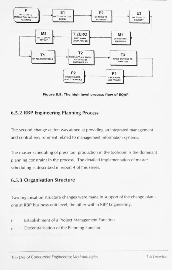
Figure 8.9: The high level process flow of EQAP
6.5.2 RBP Engineering Planning Process
The second change action was aimed at providing an integr ted m n g m nt
and control environment related to management information y t m .
Th master scheduling of press tool production in th toolroom i th d min nt
planning constraint in the process. The detailed implementation of m t r
h duling is described in report 4 of this series.
6.5.3 Organisation Structure
Tw org ni ation structure changes were made in upport of th h ng
n t RBP bu ine unit I v I, the other within RBP Engin rln
I.
..
II.
Th
Ii hm nt of Proj t M n g m nt Fun tion
ntr Ii ti n of th PI nnin Fun tion
f n lIrr nt n III nil
23
Report 8: Executive Summary
6.5.4 Know-how Transfer
Two competence areas were identified for accelerated transfer of know-how from third parties.
I. Die Manufacturing Practice II. Metal Forming Science
6.5.5 Tool Manufacturing Operations Development
Given a competitive position in the engineering technology of the press tools, and a capable metal forming process, the execution of the manufacturing process
lies with the tool manufacturing operation.
The fundamental operational development of the Tool Manufacturing function is the subject of report 4 in this research portfolio, and is summarised in section 7
of this report.
6.5.5 Engineering Design Methodology
The proposed new model of body and tool engineering required a concurrent
engineering process that can integrate the product design requirements of the
automobile body with the process design parameters for individual panels.
24
The key output of this concurrent engineering process is the availability of a fully
engineered, process capable, metal forming process specification.
The choice of an appropriate engineering design methodology was the subject of
portfolio report 5 in this series, and is summarised in section 8 of this report.
Report 8: Executive Summary c ... a.. E ~ - -~ -.- c
$ >-00 t >- .
-...c ....-
--E - c./) .-~ ro
00 ~
ro 00
~ c ... u.. ...c 00
---0
-
c -cr- - $
-c $
Cil 00 0 - C
~
C u.. ~ .- c
VI
E ~ c ...
VI
0
«
~-0 .- c
c ..., ~
.c
u.. Cil CilE I
.-
-- VI VI
~ VI
...,
-0
Change Plan Thrust ~ .-
---
'-a
~ ~c./) -c
t Engineering Quality Assurance
•
•
•
ProcedureEngineering Planning Process
•
,
Organisation
•
•
•
Know-how Transfer
• •
Concurrent Engineering Process
•
• •
I (see Report 4)
Toolroom Operations Development (see Report 3)
=
m dium link•
=
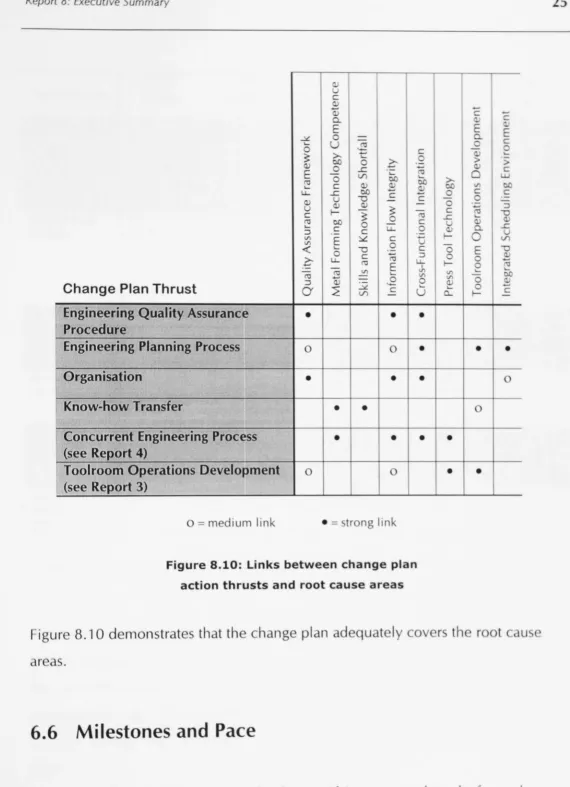
trong linkFigure 8.10: Links between change plan
action thrusts and root cause areas
I
c c
E E
a..
0 c
- 0 ~
> >
c
0
>-00 00
c c
- 0 -
---
~c -0
L ~
a.. ...c
r- 0 c./)
-E -0 ...
r- 0 ~ ~
VI - 00
0 ...
'
-Cl... r- -c
•
•
•
• •
Igur 8.10 demonstrates that the change plan adequately 0 r th root u
6.6 Milestones and Pace
u r .11 th h ng
n
b
p In r uIt
rh
r n r th th Ii In
multi-t n ir nm nt lik RBP h In pr ti \it
1\
IIllIt
In t w rkl
111 n urr nt n In (In I f th T L
[image:38.673.44.615.27.815.2]Report 8: Executive Summary
1992 1993 1994 1995 1996
Parameters CHAOS CONTROL SIMPLIFY FAST WORLD
RESPONSE CLASS Organisation Geographic Process based -Focused org. - Teamwork -Profit centr
based by product based accountabilit) -Reduced - Lean manning
Functional product range - Toolroom
layout for flow
Project Mgt. Project Team Project Mgt. -Contracts impli led Hi h
Process based process Process in planning throu hpu
under place achl m n
development -Master Schedule in
place
Technology Uncompetitive Simultaneous Common die Forming Proce s Die Standards engineering to standards with technology capability
new standards Honda capability goal achie d
Projects in -R17 5Dr - P38A -Accord Child - HH-R 4 Dr - B 0
Delivery Parts - R3
- PR3
Financial Forecast Estimate perf. Reduced fi ed - World
achievement improvement costs competitiv pricing - 10% RO
lead Time 140 120 100 0 80
(Wk )
[image:39.677.53.630.48.1020.2]DO- QP
Figure 8.11: Change Plan Goals and Milestones for RBP Engineering 1992-96
(Source: RBP Engineering 1994 Business Plan, January 1994)
Not th t cro s the top of the table the stages from the chang mo I (Ar t
1 I igned to ea h year, and reflect the progre s in rform n in th
tw Y this research proje t. Th mo t ignifi nt of th
hang ar ociat with the sim lification t g, n pi
nn
t ur urln 1 94, whi h w the pi otal e r in th u
th
h
nn.
I h ~ > f • n urr nC En In l rin I th d 10
Report 8: Executtve Summary
7.
Manufacturing for Design
7.1
The Creation of Focused T oolrooms
Six thrusts were identified to form the framework of the action plan, a 0110\
7.1.1 Creating Specialisation
It was decided to focus each operating unit as follow:
- Small Oi No.1 Shop, Swindon
No.2 Shop, Swindon
'T' Building, Cowley
- Larg Die (3600mm - 4600mm)
- M dium Oi (1 800mm - 2700mm)
An organisational template was developed for ea h m nuf cturing unit
in figure 8.12.
Manager Patterns
Teams Teams Teams
Manager
I
I
FInING BEDDING INSPECTION TRYOUTI
Teams Teams
- - - Process Flow - - - -...
h wn
Figure 8.12: Organisation Template for Focus Tool Manufacturing Units
(source: a s 1996)
lh >11 urr nt n In (In
2
[image:40.673.60.626.23.976.2]Report 8: Executive Summary
7.1.2
Establishing Operational Targets
Analysis of the business model demonstrated the need to re-balance throughput
and overall headcount. A capacity review was conducted for each un it, to
clearly identify capacity bottlenecks, and define the appropriate faci I itie and
manning balance.
The conclusion of this analysis phase enabled the consolidation of throughput
and manning targets that could be used to brief the management teams of ea h
manufacturing unit, and to describe the impact of the propo ed change on a
business model.
Tool Before After
Manfg.
Unit Dies People Dies p.a. P opl
p.a. Hrly. Staff Dies % Hrly. % St ff
Large
Medium
Small
Totals
T bl 8.2
f
u tompul
"':
55 454 58 78 42 21 1 (54) 46
88 245 38 219 149 220 (10) 19
132 * * 230 74 70 6
699 96 501 (28) 71
Table 8.2: Throughput and Manning Summary before, and
after, focus Toolroom Implementation.
(source: Presentation to Rover Group Board Feb. 1994)
omp res the manning and throughput for en riO b for
Iroom implementation. The step impro ement shown w
r venu nd substituted into pro-form profit n I
h un it. Figur 8.1 3 how the con olidated po ition for tot I t
m nuf turin
7
ht
r
n llrr'lll tn In rinnd
0
1
%
(21)
( 0)
(26)
ft r
t
unt
Report 8: Executive Summary
1993 1995
Template
Variance
Gross Sales Revenue
30.6Less outsourcing
(1.7)Net Sales Revenue
27.9 28.9 1.0Operating Costs
Direct Materials
Payroll (Manpower Costs)
24.2 19.9 4.3Depreciation
2.2 1.7 0.5Overheads
5.9 5.4 0.5Group Assessments
1.0 0.6 0.4Total Operating Cost
33.3 27.6 5.7Operating ProfitJ(Loss)
(5.4) 1.3 6.7 [image:42.671.113.546.96.376.2]Return on Sales
% (19.4) 4.5 23.9Figure 8.13: Summary profit and loss account templates for the
proposed RBPE focus tool manufacturing implementation.
(source: Woodcock 1995)
7.1.3 Simplification of the Manufacturing Process
Three action steps were taken:
i. Toolroom Layout for Flow
ii. Facility Matching
iii. Addressing Capacity Bottlenecks
- Large tool tryout capacity at Swi ndon - Inter bay transfer units at Cowley - Tryout capacity at Cowley
29
-
Report 8: Executive Summary
7.1.4 Minimising Disruption of the Manufacturing Process
Part of the change plan concentrated on creating an environment within tool manufacturing which minimised disruption. There were five action elements as follows:
7.1.4.1 Centralised Material Control
The M2 event definition required availability for the tool build team of the whole parts kit for the die. To increase management control of material it was decided to centralise this activity at each site.
7.1.4.2 Manufacturing Process Link to EQAP
Three 'M' events were defined to place the tool manufacturing process within
the overall EQAP stage/gate framework. Figure 8.14 positions these events in the high level process flow of die manufacture and summaries the key requirements at each event.
So Thai
TOOL MANUFACfURE PROCESS
BIW DESIGN LOW SPEND TOOL DESIGN HIGH SPEND
PATIERNS CASTINGS MACHINING MARSHAlJ..
M2
E3 EVENT MI EVENT M2 EVENT
I
OK 1'0 MANUFACI1JREI
ICASTING COMPLETIONII
PRE-BUILD EVENTI I
SignOff:- - All castings sound and - All madlined Items ok ToolDesiln dimensiooa1ly correct. and manhaI\ed. PlnemsModels - N.C 0. .. Keller Aids - All ill:ml. iD P.O. 10 Poly Models available and oIL haDeI.
By:- - All RqUiftld dW", info 'OK' 10 Macbioe. available IIId clearly BIW. Tool Desilll
uodmtood. Tool Manufaclure. 'liyoul
ProductiOD
KnowD 11 nung and lDpulllo biBh spcod Bwld widiiD a Toolina COlli process checked. ProduC:lIon
.,alD&! I "Ike in Envvoamall !be pouDd design.
TOOL BUn.o M3 TRYOlTT TOI.2.3.PI.2,3 M3EVENr
BUn.o COMPLETE
- Verify Tool Bwh 10 rcquind qualilY.
- AU pouible pre-qyOUI work doac.
Tools binI! 10
C\I$Iomtt
[image:43.675.112.531.574.889.2]YIIlt ICOOCI
Figure 8.14: High Level Die Manufacturing Process Flow, including "M" Event Descriptions
30
Report 8: Executive Summary
7.1.4.3 Master Scheduling
Systems developments were undertaken to establish an information ne or that
fulfilled the requirements of a manufacturing planning and control
out by Vollmann et al (1984). Figure 8.15 shows the information flo
annotated with the RBP system names.
RESOURCE PLANNING
ROUGH CUT CAPACITY PLANNING
•
CORPORATE PLANNING
BUDGET
ORDER RELEASE OPERATIONAL
• CONTROL
I
CUSTOMERS!
DEMAND MANAGEMENT
[image:44.671.46.628.205.978.2]and i
Figure S.lS: Implementation of an Information Structure for effective
Manufacturing Planning and Control in RBPE
7.1.4.4 Shifting / Crewing Strategy
h
IIIh n
w limin t th ntin nlI
18
H ur hi tttrnm
a
ur n nti nI
h
iftP tt rn
t ntinuit 'm
nnln .Tht U. )1 n urr nt n If1 on \1 th T
et
Report 8: Executive Summary
7.1.4.5 Quality Infrastructure
The "Dry Sui Id" centre was strengthened with additional co-ordinate mea urln
equipment and a scanner/digitiser.
7.1.5 Structure for "Make or Buy" Policy
Type of Tool
Draw
Trim & Pierce
Flange & Restrike
No.2 Toolroom
Main Flow
Punch
B'holder
Upper die
U'die - 1 piece
pedestal +
cutting edge +
cam drivers L'di
- 1 pie e stripp r
L'di - 1 piece
buck & pod Loose pedestal Integral U'die
Spring pad
Small MIC
Centre
Gauges
Local st Is
CAMS
S rap cutters Gauges
Lo al t els
CAMS
Cowley or No.1
Toolroom (or
Outsource
Turned it m I
spring pin
Turn d it m Lift m chani m
Running top
top bolt
A Trim & Pi r
+ flange stripp r
Table 8.3: Sourcing evaluation of Core and
Non-core elements of Large press tool manufacture.
7.1.4
Effective Financial Performance Measurement
It w
o
th t th m a ur m nt tem ch ng from thm th d, to n on m ur
m
ntofarn
lu ., t n urr 'nt En 111 (In 1\1 th )/
Outsource
Ip r , TO
pring
bo
Report 8: Executive Summary
7.2
Change Plan Implementation
The change plan to implement the "Focused Toolrooms" strategy in RBPE
comprised four elements:
I.
Operational Plan and Development and Approval
A dedicated project team translated the chosen strategy into the detailed
action plans to enact the operational changes needed to create the focused
Toolrooms.
ii.
Organisation and Facility Re-structuring
The selection, appointment, and announcement, of the leadership teams
for each unit enabled the next stage of decision-making to be conducted in
the open. The new unit management teams took over responsibility for
progressing the implementation of manpower redeployment and facility
re-structu ri ng.
III.
Consultation and Involvement
Immediately upon publicly announcing the proposed Focused Toolroom
strategy a formal framework was initiated to facilitate consultation with all
effected parties. A high priority was placed on the full communication
with, and involvement from, the Trade Unions as the major employee
representatives.
- - - -
- - --The l',p of Concurrent Engint't'ring ,\fethodologies
Report 8: Executive Summary
iv.
Rover Group Product Plan DemandsThe delivery of the "Portfolio" projects within the Ro er Group pro u
plan was a strategic target of the proposed changes to the Tool room
operations. The timing and level of demand of each ne ehicle proje t,
and the relationship one to another, was seen as crucial to ucce ful
change management in the transition period.
1993
I
~
1994
I
~
1995
I
1996
1997
Plan Dev't
& Approval
Rover Board Approvals
Tool Manuracturing
SlralO\lY Group
Orga n isation
& Facility
Re-structuring
Consultation
Manpower Redepklyment
Facility Restructunng
r<.=========-~----
---Structure for Involvement
IC::=========!._ ... ___ ._.
HH-R 4 Door Project
Product Plan Demand
R3 3 & 5 Door Project
[image:47.673.44.628.37.992.2]CB40 3 & 5 Door Project
Figure 8.16: Overview of the Focus Toolrooms Change Plan
Figur 8.16 shows an overview of the whole change plan. E h of th
f
h ng pi n
I
m nts i hown. The bars de cri b th pnn ti itwithin h
I
m nt. The horizontal a i re re ent fi r tim linTh' ~'f n 'urr nt L n In (In
ur
tr
,
III
Report 8: Executive Summary
7.3 Rover Group Project Commitments
The following dies were chosen as the core of the 1994 new tool manufacture workload supporting the R3 3 Door vehicle programme, SOP September 1995, and the HH-R 4 Door vehicle programme, SOP January 1996. CB40 dies were manufactured during 1995 and 1996 for SOP August 1997.
R3 3 Door
Large Dies:
Medium and Small Dies:
HH-R 4 Door
Large Dies:
Medium and Small Dies:
Bodyside R & LH
Front Door Outer R
&
L HFront Door Inner R & LH Bonnet Outer
Bonnet Inner
Bonnet Locking Platform Dash Lower RHO
Dash Lower LH 0
26 medium and 21 small dies comprising 15% of the total dies of that size required on R3
Bodyside R & LH
Roof - Fixed Roof Roof - Sunroof
50 medium and 20 small dies comprising 24% of
the total dies of that size required on HH-R
35
Report 8: Executive Summary
CB40 Project
The following dies represented the major RBP work content on CB40, with the
balance of dies outsourced:
Large Dies:
Medium and Small Dies:
Bodyside 5 Door R & LH Roof - Sunroof
Rei nforcement - Roof
Bonnet Outer
Bonnet Inner
Main Floor
Crossmember Heel Board
Rear Floor
31 medium and 57 small dies comprising 29% of
the dies of that size required on CB40.
36
Report 8: Executive Summary
8.
Engineering Design Methodology
It is evident from the I iterature that the terms "Product Development- and
"Engineering Design" are often used interchangeably. Product Development is often considered to be a range of activities spanning from marketing to
manufacturing (Ulrich and Eppinger
1995,
Andreason & Hein1987).
Engineering Design is considered to be a sub-process of product development (Wallace
1990,
Finkelstein and Finkelstein1983).
In recent years, there has been a shift in thinking about the design process. It has changed from an essentially sequential paradigm (Shigley and Mischke
1989,
Pahl and Beitz
1984),
towards an emphasis on integration and concurrency of product and- process development (Winner et al1988,
Bullinger and Warschat1996),
usually referred to as "Concurrent Engineering" (Cleetus1992).
In addition to integrated product and process development other researchers emphasise the importance to the success of product development of accurately capturing customer and market requirements (Pugh
1991,
Clausing1993).
The field of automobile body and tool engineering has been one of the first to exploit CAD technologies (Whitney
1995).
Also, as a critical path sub-process of automobile development, the important influence of engineering practice in thisprocess stream has been recognised by researchers into automotive product development (Ward et al
1995,
Clark and Fujimoto1991,
Womack and Jones1990).
However, the focus of this research has been at a high level in theproduct development process stream, and offers little insight at a detailed design
methodology level.
The wide range of the I iterature on design theory and methodology contains consistent themes regarding the basic structure of design activity, and practically
useful frameworks to guide decision making in configuring the design process.
37
Report 8: Executive Summary 38
Table 8.4 summarises the focal activities for each stage in the de ign proce an
identifies the corresponding issues for design managers.
Design Process Focal Activities Design Management Issue
Sta
e
Concept Analysis
Synthesis
Application of rules
Embodiment Simulation C E & kill
Integration CAD & kill
Detail Automation C D Configuration
Execution Costs
Evaluation Target Confirmation Role of prototyp imul tion
Design support C E Tool
Table 8.4: Summary of Issues arising from the literature on design
Body and tool engineering is concerned primarily with th ution of ti
product concepts, and te hnically over-constr ined d Ign Thi im Ii th
pr -eminence of importance in the design methodology of:
I. Embodiment design of automobile bodie tool.
II. The nalysis and evaluation of design solutions influ n ing th tot I
rchitectur and sub-system performance.
8.1 The Role of I nformation Technology in De i
g
n
Methodology
h
n ntiI
nt th of th r i \\ II kn vn nntinu ut tri th