ERRATA
Paragraph 1 .. 2 .. 1
AC input range 70 - 130 VAC.
Page 10
S-100 Bus Motherboard Active-Termination Logic.
Rl4 and RlS connect
to +8 VDC.
Rl6 and Ql emitter connect to ~round.
S-100 Bus Motherboard.
+8 VDC enters motherboard on Terminals 4 and
s.
+16 VDC enters on Terminal 1.
Page
11S-100 Bus Motherboard Active-Termination Logic.
Rl4 and RlS connect
to +8 VDC.
Rl6 and Ql emitter connect to ground.
Page 13
S-100 Bus Motherboard Active-Termination Logic.
Rl4 and RlS connect
to +8 VDC.
Rl6 and Ql emitter connect to ground.
Page 13
S-100 Bus Motherboard Active-Termination Logic.
Rl4 and RlS connect
to +8 VDC.
Rl6 and Ql emitter connect to ground.
NOTICE
CONTENTS
PAGE
1.1.0 INTRODUCTION 5
1.2.l MCS-112/122 GENERAL DESCRIPTION 5
1.2.2 RM-12/RM-22 GENERAL DESCRIPTION 5
1.2. 3 THEORY OF OPERATION 6
1.2.4 RECEIVING INSPECTION 6
1.4.l DIMENSIONAL DATA 9
1.4.2 SCHEMATIC MCS-112/RM-12 10
1.4. 3 SCHEMATIC MCS-122/RM-22 11
1.4.4 PARTS LISTS (CHASSIS MOUNTED PARTS) 12
1.4.5 POWER SUPPLY PC BOARD ASSEMBLIES 13
1.4.6 MOTHER BOARDS 14
1.4. 7 GENERAL ASSEMBLY VIEWS 15
1.5.1 TEST AND CHECKOUT 17
GENERAL INFORMATION
1.1.0 INTRODUCTION
SECTION I
This reference manual supplies information on the TEI, Inc. MCS-112/122
RM-12/22 Microcomputer Systems. If additional information is required, please
contact your local dealer or representative.
1.2.1. MCS-112/122 GENERAL DESCRIPTION
The MCS-112/122 is TEI1s solution to your system needs. The TEI
Micro-computer System features the following:
--The MCS-112 offers a high quality constant voltage transformer (CVT) power
supply which is rated conservatively at BV @17A, ±16V @2A, over a voltage
range of 95 to 130V AC; while the MCS-122 offers a CVT power supply rated \
at BV @3DA, ±16V @4A, over a voltage range of 95 to 130V AC.
--The MCS-112 offers a 12 slot mother board, while the MCS-122 features a 22
slot mother board. Both come with all connect6rs fac~ory installed and tested;
a Mate-N-Loc connector on the reset line for dedicated systems; screw terminal
connections for the DC power leads; and provision for a front panel.
--The MCS-112/122 gives you a rugged industrial quality chassis; a back panel
punched for eight 0825, two 0837 connectors, and cable clamp for ribbon cable;
and the front panel features a lighted power switch and a reset switch.
The MCS-112/122 is designed to meet U.L. 478 specification for those who
require commercial or industrial application. TEI, Inc. has been a quality
electronic manufacturer for ten years, building highly reliable electronic
sys-tems for industrial use. Many of these are U.L. approved with some approved
for use in medical equipment where only the highest quality and dependability
will do. By purchasing the MCS-112/122, you have obtained the best
Micro-computer Mainframe available today!
1.2.2. RM-12/RM-22 GENERAL DESCRIPTION
The TEI RM-12
&
RM-22 are the same as the MCS-112/122 described aboveexcept for the ruggedized Retma Rack enclosures (19" W X 7" H Panel Mounting
with chassis slides).
6
1.2.3 THEORY OF OPERATION
The MCS-112/122 can be considered as two separate electrical components.
These are: (1) The Power Supply and (2) the Mother Board.
(1) The Power Supply is designed to deliver three (3) DC voltages to the
Mother Board, +BV ®17A, ±16 ®2A for the MCS-112; +BV ®30A, ±16V @4A for the
MCS-122. Our CVT Power Supply also provides 1% line regulation from 95
to 130V AC input. This regulation is due to the use of a constant voltage
(or Ferroresonant) transformer.*
(2) The Mother Board uses the "S-10011 bus format and will accept all cards
designed for this configuration. The purpose of the Mother Board is to
provide the various signals and power paths from card to card and have all
signals available on all connectors on the Mother Board.
1.2 .4 RECEIVING INSPECTION
Immediately upon receiving your MCS-112/122 inspect all contents for damage
which may have occured during shipping. If your MCS-112/122 arrives
damaged or incomplete contact your dealer so that he can take appropriate
DIMENSIONAL DATA
MCS-112 Dimensions: 17.25 Wide X 7.25 High X 12 Deep
MCS-122 Dimensions: 17.25 Wide X 7.25 High X 19.5 Deep
RM-12
RM-22
Dimensions: 19" Wide X 7" High Rack Panel X 13" Deep
Dimensions: 19" Wide X 7" High Rack Panel X 19.5 Deep
NOTE: Slide Bracket (#13926-02) will permit the RM-12
to be mounted up to 2211 deep racks, and the RM-22
to mount in up to 28" deep racks.
19.0
1-6.97
Front slide bracket
fi / TEI P/N 13925-01
u
"A"
·"--I
i..__,><--H_
1-i- .._________.
l. 735RM-12/22 OUTLINE DRAWING
r
Rear slide bracketTEI P/N 13926-02
o·
17.75
-OTM A
RM-12 13.0
RM-22 19.5
D
C
B
A
..
3J
2ll5 \/AC INPUT~
..&, CONNECTED AS SHOMd
·13602-02.(50 HZ)
~ T1'113l28-02(60 HZ)
REVISIONS
ZONEILTRI EQ NO. I DESCRIPTION DATE !APPROVED
A I I ADDEO MOTHER BOARD AND 220 V OPTION 12/1/78
0
2 20 YAG INPUT: (I) REMOVE JUMPERS TBI-I TO 3
AND TBl-2 TO 4 (2)JUIIPER TBl-2 TO 3. FAN
&-SW! CONN. 00 NOT CHA1'1GE
1
-1 PCB I POWER SUPPLY 13121
I
BLK
r-CI
WHT 41
L _ _ J
B
JI- -~R-2
~ ~
.:-1
ru
6 :I
-RI 820il.
- - 1
I
I
11
r--11
I - ... av
~ 1 5 A
PCB 2 MOTHER BOARD 13621
2W 10:...:"!...:.o...---- .
E1~;J;
~
+ev + i 6 V - - - ,I
I
ri
115VAC 50 HZ ONLY
OR 60 HZ ONLY (DEPENDS ON
TRANSFORMER) NOTES: ~ 3
"0
IIIOTl:'._S_QQ___ I~ V _ .TEI. l'/N- l!;iJ.-:Q.l;Jl . ,J.O,!lll!L . ..30.lL ... LE.LPA! 152Hl88 ..
. 3WF SOOVAC TEI PIN 1543-006 ... __
RI TlilllLCR.4... GOSA_IEI. P/!Ul82.5:-.0.43.
CR5 R712 VARO TEI P/111_ 4£115-()17
4 I I I I I
I
I_t =4' "=COM~Rl3
\~16.n..
~ 180.f"\
>
I I I I I I I I I I f_ I I
F2
I
I)I S~G si i2®16V
i
t
@J I 2A R2I
I@)
C3a200 I
112W 10%1 : I
1
R3 I I CRI 820n. j J IN5221 V2W 10%
., @6! '4@16V
F3 I I 2A 5A 3AG I I
I I
I I
-l6V--<1>----~
Rl4
IQ.{"\_
...
15171'C91''f\f6181'o112 C4 THRU C 12
10 MFD 20VDC
RI-I I 180.f"\ ffYP) I
R~ll I I I I I I
- - - . _ _ _ I I _ _ _ _ _ _ _ _ _ _ _ _ _ _ _ _ _ _ _ _ _ _ _ J
QTY PART NUMBH
Dlll!ENSIONAL TOLERANCE UNLESS NOTED OTHHWISE
.)( :!: .06 .)()( :!: .02
.)()()( :I: .010
ANGULAR ± . 5 DEG
DESCRIPTION
CONTRACT NO.
SIGNATURES DR
Di:$
CODE IDENTI REF DES i lTUII
TEXAS ELECTRONIC INSTRUMENTS.INC
HOUSTON, TEXAS
MCS-112 SCHEMATIC
SURFACE FINfSH IN MicllO!NCHl!S ~C:'.lt!'.K~---~-+---11
1 . - - - l l - - - l RMS UNLESS NOTED /
(!!~L.£~:fl.id!!~:..J~~!,l.7:::::T.=:;-;;;:;;;;:;;;-;:;;;;r,;;.,.;;_;,;;---1 (!!~L.£~:fl.id!!~:..J~~!,l.7:::::T.=:;-;;;:;;;;:;;;-;:;;;;r,;;.,.;;_;,;;---1
w-S
L - - - t . - - - l O T H H W I S E V APP SIZE CODUDENT DWG NO.
A
MCS-112 MATHIAL C
nn,
13154NEXT ASSY USED ON APP
APPLICATION SCALE REL eo NO. Sffl:i!l' OF I
3
•
2I)
C
1:1
D
C
B
A
4
115 YAC INPUT:
CONNECTED AS SHOWN
220 VAC INPUT:
(I) REMOVE JUMPERS TBl-1 TO 3
ANO TBl-2 TO 4. (2)JUMPER TBl-2 TO .3. FAIi! S
SW I CONN. 00 NOT CHANGE.
WHT Fl IOAMP
3 AG
ri
I 15VAC 50 HZ ONLY
OR
SWI
r - --, ! i.-- 3 I
i
II
2i_..-- 4/
+t
L _ _ _J
FAN
60HZ ONLY (DEPENDING ON
TRANSFORMER)
C 5 n
T
,-_!4
NQTES:
C~C2 45,000 MF, ISV TEI PIN 1521-068
i:::;
C3,C4 10,000 MF ,30 V TEI P/N 1521-088 CS 5 MF, 660 VAC TEI PIN 1543-001 CRI THRU CR4 SOS4 TEI PIN 4825--043 CR 5.~_6__ TELP/ N 4815-017
NOTES:
~ 4
13575 C50 HZ) 13214 (60 HZ)
3
i
PCBI POWER SUPPLY BOARD PIN 13131 ;r-
--JI- CR5 I 9 }
~
5 I 10
r -
-I Fl l5e:) +8VOC6 : I
l
20A 3AG 3 1 30 AI
I I Cl~ RI
12
I
T
5
1~i~·1.I
~ I I I -t-16V1
I
-;
,...1.... ~ 4 " _ , +avI - __ I
I
I CRS I- ---i
~
8 1"'9
. ~
~
II
( I I 11/11>1 I I C2
_ _ 1
v
20A 3AG R2 seon Rl3 1eon Rl2 IBOr.JI )
!CRI JN5221
2
I
REVISIONS
ZONEILTRI EO NO DESCRIPTION
A ADDED MOTHER BOARDS 220V OPTION
PCB 2 MOTHER BOARD PIN 13610
Rl5 1301"\.
Rl4 10.n.
Q2 2N390S -t8V
RII
75r.
j-DATE !APPROVED 11/2/78
--1
180~i:.YP.)i
. I
RIO
751"\.
is
7 ; ' 1;9 7;11r
1 6 1 8 1101'2·04 C4 THRU Cl2
TIP30 10 MFO 20 voe
R9-11
6
1 1 ,:1 <i{.1 1<1 I "
~ '@' ,o@,+16~~C -ISV
I I I I I I I C4
IOA 3AG
MCS-122
L ___ _
QTY PART NUMBER DIMENSIONAL TOLERANCE UNLESS NOTED OTHERWISE
.x ± .06
.xx ± .02
.xxx ± .010
ANGULAR ± .. 5 DEG
DESCRIPTION
CONTRACT NO.
SIGNATURES DR J; 6".<>c..HTRUP DES I I i I I I _J
MANUFACTURER CODE IDENTI REF DES I ITEM
TEXAS !ELECTRONIC INSTRUMENTS,INC
HOUSTON, TEXAS
MCS-122 SCHEMATlC
I
I
I
SURFACE FINISH IN AAICIIOINCHES ~ .. ~~ - - - + - - - 1 R M S UNLESS NOTED
J
ENGR C /V!f r .z....: //-8· )!JOTHERWl~E APP SIZE CODE IDENT DWG NO. HY
MATERIAL /l)n~0,1,, f-1~ ,,.. "'"''"" 13232 NEXT ASSY USED ON
APPLICATION SCALE SHEET
3
t
2D
C
13
1.4.4 PARTS LIST
The following parts list is included to supply the necessary part numbers needed for ordering replacement parts.
MCS-112/RM-12 MCS-122/RM-22
REF TEI REF TEI
DES DESCRIPTION P/N DES DESCRIPTION P/N
CHASSIS MOUNTED PARTS Chassis Mounted Parts
PCB2 '* Mother Board 12 Slot 13620 PCB2
*
Mother Board 22 Slot 13610PCBl
*
Power Supply 13120 PCBl * Power Supply 13l31JTl Transformer (60Hz) 13128-02 Tl Transformer (.60Hz) 13214-02
Tl Trnasforrnsr \ 50Hz) 13602-02 Tl Transformer (50Hz) 13575-02 .
C4 Cap, 3MF @660 VAC 15.43-006 C4 Cap, 5MF @660 VAC 1543-001
PC8.1··Jl Soc:kst Housing, 8 CKT 2] 22-011 PCBl-Jl Socket Housing, 12 CKT 2122-013
PCB2-Jl Socket Housing, 2 CKT 2122-021 PCB2-Jl Socket Housing, 2 CKT 2122-021
Fan Fan 2610-0Jl FAN FAN 2610-0ll
Filter, Fan 13146 Filter,Fan 13146
SWl Power Switch 5ll3-001 SWl Power Switch 5110-001
SW2 Reset Switch 5110-005 SW2 Reset Switch Sll0-005
Fl Fuse SA 250V, 3 AG 5173-062 Fl Fuss lOA 250V, 3 AG 5173-079
Power Cord 6080-003 Power Cord 6080-003
Rubber Feet 1419-001 Rubber Fest 1419-001
Boot, Rubber Cap 1592-003 Boot, Rubber Cap 1592-003
Card Guide 1750-004 Card Guide 1750-004
Slide Bracket, Front 13926-01 Slide Brac::kst, Front 13926-01
Slide Braeket, Rear 13926-02 Slide Bracket, Rear 13926-02 ·,
*Refer to pp. 13 & 14 For P .C. Board Data.
REF DES PCB Cl C2, C3 CRl thru CR4 CRS El Fl F2, F3 J R.L' R2, R3
POWER SUPPLY PC BOARDS
PC BOARD #13120 MCS-112/RM-12
•,-
I t'
, /'
,I; )0/\9+ VSI u
u :;
NOWWO) Vt
'./
ONO OMl'° • ev +16V -l.ttlf rn Rl
E3
("'
'-... ) 10000 MFO
( l JO VDC + 1521-068
..
{no$\
4$000 Mf[)
15VDC
bbbb
TEI l"N IS21·068
O
JI1
4 1
6 '
• 1
..
PARTS LIST
TEI
DESCRIPTION PIN
F/!B Power Supply 13121
Cap, 45,000 MFO, 15
voe
1521-068 Cap, 10,000 MFD, 30voe
1521-088Diode 60S4 4825-043
Rectifier, R702 4815-017
#20 Ga Jumper 6009-003
Fuse, 20A, 32V, 3AG 5173-029
,•
Fuse, SA, 250V, 3AG 5173-022
Pin Header, 8 CKT 2122-005
RES 820
n
1/2 W 10% 4725-329REF DES PCB Cl,C2 C3,C4 CRl thru CR4 CR5,CR6 El Fl,F2 F3,F4 Jl Rl, R2, R3,R4,
PC BOARD #13130 MCS-122/RM-22
.
"
; I'--<
I' .... - .
;,', ')
NOWWO) )Q/\
',)t-. • '',)t-. II • ). , ~.o_;
/
PARTS LIST
TEI
DESCRIPTION P/N
FAB Power Supply 13131
Cap, 45,000 MFD, 15VDC 1521-068 Cap, 10,000 MFD, 30VDC 1521-088
Diode 60S4 4825-043
Rectifier, R702 4815-017
#20 GA Jumper 6009-003
Fuss, 20A, 32V, 3AG 5173-029 Fuse, lDA, 32V, 3AG 5173-022
Pin Header, 12 CKT 2122-007
Res 680
n
l/2W 10% 4725- 32114
MOTHER BOARDS
fil
CAPAC ITV13630 8 Slot
13620 12 Slot
13612 22 Slot
PARTS LIST REF
DES P/N DESCRIPTION
13631 FAB TEI
13621 FAB TEI
13611 FAEI TEI
C3 1562-002 CAP .lMF
C4-Cl2 1580-001 CAP 10MF®20V
2122-020 PIN HEADER 2CKT
2125-011 100 PIN EDGE CONN
Ul 3100- 017 IC CHIP 748 MIL
3190-002
re
SOCKET 8 PINRl4 4741-145 RES. lOn 1/4 W 2%
RlO,Rll 4741-229 RES. 75n 1/4 W 2%
Rl5,Rl6 4741-252 RES. 130n 1/4
W
2%Rl2,Rl3 4741-266 RES. 180n 1/4 W 2%
Rl,R9 4784-002 11 SEG. RES.
NETWORK 180n
CRl 4840-026 DIODE IN5221
Ql 4864-005 TRANS. 2N3904
Q2 4864-007 TRANS. 2N3906
Q4 4873-011 TRANS. TIP 30
Q3 4874-035 TRANS. TIP 29
i - - -
-I
I +16V ---.11---~
l
~8V +8VI '2@15"
! ~
I ~NO I
[
I
I
b+lfl
J 2ARl3
18() A
R/2 180.n. I I I I I 3 ~-16V
f
JI CRI N5221 I II -16V
Rl5 130{). C3 .IMF Rl6 130n. 03 TIP 29 04 r1P30
8 SLOT QTY l 1 9 l 8 l l 1 2 2 2 9 l l l l l IOMF 20\1 (x9) SIZE
8.500 X
8.500 X
8.500 X
12 SLOT QTY l 1 9 l 12 1 1 1 2 2 2 9 l l 1 l l
---,
I I IRH IBOn. 1 1
TYP.
R9-II
l
I--
-
--
--
-
-
- -
-
-
-
- - - -
- --- ---'
6.800 10.050 17.500
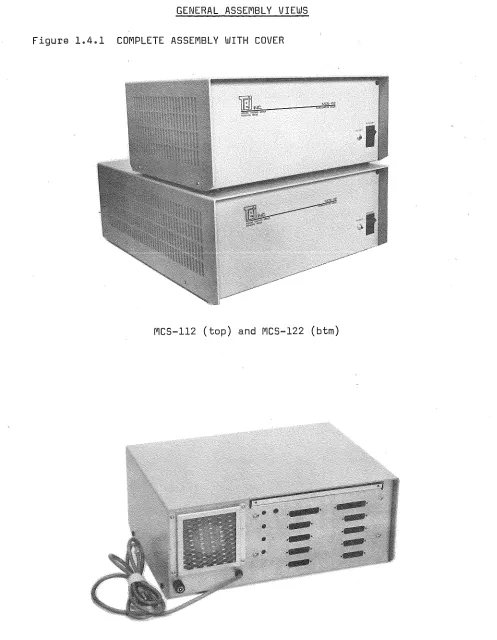
GENERAL ASSEMBLY VIEWS
Figure 1.4.1 COMPLETE ASSEMBLY WITH COVER
MCS-112 (top) and MCS-122 (btm)
[image:15.612.60.557.59.699.2]1.5.1
TEST AND CHECKOUT
Follow this procedure to check mainframe for proper operation.
1)
Visually inspect wiring from power supply to motherboard.
2)
Check power supply connections for tightness.
3)
With power switch off, plug line cord into AC socket.
4)
Press Power switch to light indicator in switch.
5)
With DC voltmeter, check for +8 VDC to +11 VDC between pin l {+)
and pin 50 (-, Ground) on any connector on motherboard.
(1) >6)
Move {+) lead to pin 51 and check fo( +8 VDC to +11 VDC.
7)
Move voltmeter {+) lead to pin 2 and check for +16 VDC - +18 VDC.
8)
Move voltmeter
{+)lead to pin SO, (-) lead to pin 52, and check
for -16 VDC.
9)
Move (-) lead back to pin SO. Move
(+)lead to pin 75, then to pin
100.
Neither pin should show any voltage reading.
10)
Run{+) lead up and down remaining pins. Each should read about
+2.4 VDC.
{l)Pin 1 is nearest front left corner.
Pin 51 is directly behind it.
Wi.
INC. 5075 S. LOOP E., HOUSTON, TEXAS 77033MicroFrame Check List
(713) 738-2300, TWX: 910-881-3639
YOUR MAINFRAME
rs
A:
MCS-112
RM-12
~MCS-122
TRANSFORMER
w.o.#
RM-22
S/N
:_-'--"---'--'----CONS I ST S OF:
-,, (1) MAINFRAME
-.-_ -.-_
(2) MAINFRAME USER'S MANUAL
_ _
(3) RUBBER FEET (4 FOR MCS-112 ONLY) (6 FOR MCS-122 ONLY)
___ (4)
FUSE
5AMP (USED ON MCS-112
andRM-12)
__
. _(S)
FUSE 10 AMP (USED ON MCS-122
andRM-22)
___ (6)FUSE HOLDER CAP
NOTE:
REFER TO USER'S MANUAL BEFORE OPERATING; ESPECl~LLY
WARRANTY REGISTER AND SECTIO.N.
1. 3FINAL QC CHECK-OFF:
___ ABOVE ITEMS CHECKED
_ _
IF
SOHz,CHECK LABELING
OUTPUT CONNECTORS LABELED
___ S/N ON UNIT AND PROPERLY RECORDED
QC INSPECTOR:
----,._.;;..._..._____ _
SYSTEM W. O.#
___________
_____.__ _
'
DA TE : ______ ..._/ ________
'
DATE SHIPPED: ____________ _
CARRIER: ____________
__
CUSTOMER: _______________ _
Sales Order#
---SOHz
WHITE COPY - QUALITY CONTROL CANARY COPY - OFFICE
PINK COPY - SHIPPING GOLDENROD COPY - CUSTOMER
lii.
INC.