Digitizers
This section describes the digitizer connections and gives walk-through instructions for the CADDRAFT interface to your digitizer.
Digitizers allow you to draw in two ways.
The first method is called relative input. This means the cursor is in direct relation to the screen, bound by its borders, and working exactly like a mouse device.
The second method is called absolute'input. This allows you to input directly from the tablet, literally copying an existing drawing into the computer. In this mode, there is no direct relationship between the cursor position on the tablet and the cursor position on the screen.
Hardware Setup
The two most important things to do in setting up your digitizer are:
1. Make sure the interface cable between your computer and digitizer is configured like the example in the CADDRAFT manual. Configured cables are also available from Personal CAD Systems, Inc.
2. Set the switches on your digitizer like the example in the CADDRAFT manual.
Ninety percent of all digitizer problems are related directly to one of the above items.
The digitizer cable must plug into communications port #1 as does a mouse (except the Microsoft mouse). If you have a mouse connected to port #1, disconnect it in favor of the digitizer.
NOTE: Many digitizers have two or more ports on them. If choosing bet-ween the Modem or Terminal Port for connecting the cable, ALWAYS choose the Modem port.
After the hardware is installed, use the instructions that follow to align the drawing, position the menu, and select a scale.
Software Setup
The following instructions step you through the software setup.
PROCEDURE:
1. Choose INFO from the main menu commands.
2. Select parameter
#6
to establish the Database Units you wish to work with. Consult the Commands Chapter, Section 17 in your CADDAAFT Users Manual for more information on setting DBUs.3. Next determine the grids you will most likely need for the drawing. Ten possible grid sizes can be set in INFO parameters 21-30 for later recall.
4. Select #13, Input Device. This gives you a screen of input device choices. For now, it is best to use the cursor control arrow keys on the keyboard to make your choice from the following selections:
I
MOUS1 GTGO HIPAD KURTA TIGER MOUS2
Use the right arrow key to move to the name of the digitizer you will be using.
Press X to confirm.
5. Next you see the question:
I
ARE YOU SURE? NO YES
Make your selection by moving the cursor to YES. Then confirm by pressing X on the keyboard.
6. Now you will see this message:
I
Do
you
wantto scale your tablet? NO YES
If you select NO, the digitizer works like a mouse (relative input) and is limited by the boundaries of the screen.
Hardware and Peripherals
Now you may use the puck instead of the keyboard for selections that do not require typing.
If you select YES, you will see a screen with X and Y values at the top and further instructions.
The X and Y values on the screen should change rapidly as you move the digitizer puck, since the tablet is very sensitive to puck movements. If the values do not change, there is a communication problem between the computer and the digitizer. Check the cable configuration and switch . settings and be sure the cable is plugged into communications port #1 in back of the computer. If the X and Y values change when moving the puck across the digitizer, proceed to alignment.
Alignment
In order to position your drawing on the digitizer, follow the instructions on the screen or the steps below.
PROCEDURE:
1. Place your drawing on the tablet.
2. Choose either a horizontal or vertical line on your drawing. If you choose a vertical line, position the drawing so that the X values at the top of the screen do not vary by more than 10 numbers as you line up the crosshair on the puck at both ends of the line. If you select a horizontal line, position the drawing so the Y values do not vary by more than 10 numbers as you line up the crosshair on the puck at both ends of the line.
These numbers are for alignment purposes only and have' no relationship to the measurement of your drawing.
3. Once this alignment is accomplished, secure it in place and press (Return) to confirm.
Menu Positioning on a Digitizer
You need to select a rectangular area on the tablet to function as a representation of the CADDRAFT menu screen. This rectangle is like an invisible box representing the menu screen. When drawing, use this area to access menu selections with the puck.
The corners of the menu area must be set. A series of prompts are . displayed one at a time and remain on the screen until the sequence is complete. The first two prompts refer to the MENU ONLY. They are:
Select lower left corner of MENU area Select upper right corner of MENU area
Before responding to these two prompts, pick a corner or area that is out of the way of your drawing. The following steps detail for you the procedure for menu area selection.
PROCEDURE:
1. The first message
I
Select lower left comer of MENU areaprompts you to locate a pOint on the digitizer outside your drawing area to represent the lower left corner of the menu area. Use button #1 on the puck to select. If this point is located in an acceptable area of the tablet, the confirmation
I
Location Accepted validates the position.An unacceptable position produces a message saying INVALID POINT. Continue to reposition the puck until you receive the message,
LOCA-TION ACCEPTED. .
2. Next, you see this prompt:
I
Select upper right comer of MENU areaLocate a point on the tablet to serve as the upper right corner of the menu area. Press button #1 on the puck to select this corner pOint.
Hardware and Peri pherals
This establishes the menu area on the tablet and you are ready for the next part of the software setup.
NOTE: If the drawing takes up all of the tablet, you will have to complete three- fourths of the drawing and then relocate the menu to another part of the tablet to finish the remaining one-fourth of the drawing that was oc-cupied by the menu itself.
Scaling the Drawing Itself
To understand the digitizer scaling process, let's take an example.
First, select a lower left corner (LL) and an upper right corner (UR) on your drawing. Illustration of two such points are found in the Bearing Shaft drawing below.
Selection of the coordinates for the LL corner is arbitrary. Calculation of the UR coordinates will depend on their relative distance from the LL coordinates.
In this example, 1 DBU equals 1 mil. Thus,
5.000"
=
5000 mils 1.000"=
1000 milsThe equation given here exemplifies how to calculate the UR coor-dinates:
LL (X coordinate)
+
Distance in DBUs = UR (X coordinate)o
+
5000=
5000and
LL (Y coordinate)
+
Distance in DBUs=
UR (Y coordinate)o
+
1000=
10001.0 __
I..f'~
CO""'" (loUI
x-a Y-a
~~:!!~::; Wo,.ld CO_dl"a~.:, :I 000"
Bearing Shaft
If you opt to establish the LL corner at world coordinates (0,0), then the X coordinate of the UR corner would be equal to
a
plus 5000. The Y coordinate of the UR corner would be equal toa
plus 1000.As an equation, the X coordinate of the UR corner (URx) equals LLx plus the distance in DBUs. Similarly, the Y coordinate of the UR corner (URy) equals LLy plus the distance in DBUs.
In planning a drawing, you want to consider where the LL corner should be for future additions and enhancements. If you plan to add more details or expand the drawing into a full design, you may want the LL corner in a location other than (0,0) ..
In other words, the value you choose for the LL should relate to the amount of the "world" taken up by the drawing and the position of the point on the drawing. For example, if the pOint is at the lower left of the drawing and the drawing will take up most of the "world," you should give the coordinate value of -32,000 for both the X and Y coordinates. However, if the point is near the middle of the drawing, you should enter a value of
O.
Hardware and Peripherals
When these positions and calculations are established, you are ready to proceed with the scaling.
PROCEDURE:
1. The first message in this sequence asks you to
Select lower left corner of drawing area
Position the crosshair of the puck on the lower left point of the drawing on the tablet. Then, select this point by pressing button #1.
2. Respond to the next message
I
Enter X value (-32K to +32K)by typing a coordinate for the X axis, such as 0, and then press (Return).
3. After entering this value, you will then see this prompt:
I
Enter Y value (-32K to +32K)Use the same logic on this value as described above. Again, 0 is often a reasonable choice unless the drawing you are digitizing is extremely large or detailed. Press (Return) to confirm your coordinate.
4. The next message is:
Select upper right corner of drawing area
Now it is time to use the calculations in Database Units for the distance of the UR corner from the LL corner. The distance in DBUs from the lower left point to this upper right point are to be typed in as coordinates for the two following prompts:
I
Enter X value (-32K to +32K)5. Type the X coordinate value for the upper right corner and press (Return).
I
Enter Y value (-32K to +32K)6. Type the Y coordinate value for the upper right corner and press (Return).
Now the drawing is scaled. The INFO page returns to the screen.
Plotter Interfaces
Introduction
This guide provides essential hardware connections and settings for the optional plotters that work with CADDRAFT. If you have only one com-munication port, you will have to disconnect your input device when you are ready to plot. Screen prompts will advise you when to do this. Other-wise use communication port #2 for the plotter connection.
NOTE: If choosing between Modem or Terminal Port for cable connec-tion to plotter, ALWAYS choose the Modem port. /
For further details consult your plotter manual.
Follow the switch settings and cable configurations on the following pages to set up your plotter. They are included here for your conve-nience.
Output Devices
The following plotter interfaces are detailed in this package:
IBM XY 749 IBM XY 750
Calcomp M84 Calcomp M81
Houston Instruments DMP-29 Houston Instruments DMP-40 Houston Instruments DMP-41 Houston Instruments DMP-42
Hewlett Packard 7220 Hewlett Packard 7470 Hewlett Packard 7475 Hewlett Packard 7550 Hewlett Packard 7580A Hewlett Packard 7580B / Hewlett Packard 7585
Gould Colorwriter DS-1 0 JSC
Nicolet Zeta 8 822 836
AlphaMerics
Sweet P "6 Shooter"
CAOORAFT Size
A
A,BA
A,B A,B A,B C,D C,D A,BA
A,B A,B A,B,C,D A,B,C,DE
A,BA
A,B A,B,C,D A,B,C,D,E A,B,C,D A,BIBM XY750
CALCOMP M8l
PC PLOTTER
Hardware and Peripherals
~
~
C A > >
C
c:
:::0 -iCADDRAFT .
N
~
o o
:::0 U1 0
0 J:
"
>
"
o
1J->Ul
:::O-i
0
1J
o
~~O
-i " " " J:: "
JTt r > ~ JTt .... Ul 0 C 0 J:: Z -i ~ '-t -i
P-3
--..J 0 <
C C N
> C ~
-i
Sol
IBM XY749-A
CALCOMP M84-A
PC
PLOTTER
1 • • 1
~~
__ Ir--i
§
4~ ~
4
5
!:J.--:; -
~->
5
6+---+1
,-+
6
21+---1
:lo
1
2
3
4
5
6
7
8
9 10BBBBBBBBBB
CADDRAFT
DMP-29 Plottgr
PC
PLOTTER
1 ..
4----...
~1
24
r---)2
3+--
I •3
4~ ~4
2~P=l
flo
Baud Rata Switch
P-s
Hardware and Peripherals
1.
2.
CADDRAFT
DMP-40 Sarias
PC
PLOTTER
1 •
• 1
24 Ir--,..2
a+---·
-+
a
4~ • 4
5
t:J----,
•
5
6t--!
.6
2b~:lo
Entar
-P-6
To Salact
9600 Baud
Hardware and Peripherals
HP 7220 PLOTTERS
PC
PLOTTER
1
4 •1
2
4 .. - - - ..2
3.----'
I •3
4.
• 4
2~F=l
flo.
WM
OFF
1M
NORMAL
W@A
OFF
WM
000
WM
FULL
2400
IWA
MODEM
~=
DOWN
CADDRAFT
H P 7470
C)I
C)l
52
51
[) I· I
y
I
I ()
U5I
I (]
84( ) 1
I
83
I
I (]
82
o
I I
81
SWITCH
SETTINGS
CADDRAFT
Hardware and Peripherals
H P 7475
PC
PLOTTER
1 •
• 1
§
~___ ,
r --1
§
4~
.4
St:J---,
• 5
6 t - - - t
• 6
2b~
:10
DI
52
[11
51
DJ I
y
I I
C)
US[)I
I
A3
I
I()
84[ ) 1
I
83
I
I(]
82
() I
I
81
SWITCH
SETTINGS
CADDRAFT
H
p
7550
Oata Flaw Rcamotca Standalonca
Bypass OTT
Both conncactors Fcamolca
Handshakca Hardwirca Modcam
Serial Sublevel
Ouplcax Parity
Full B bit.
Baud
9600
OTT
Data Compatibility
Hardware and Peripherals
HP 7550
PC
PLOTTER
1 4 ~ 1
2
4 .. - - - ...2
3.----
1I ~
3
4
~• 4
StJ---,
• 5
6 ! - - i
~6
21~
:lo
WM
OFF
WM
NORMAL
WM
OFF
WM
ODD
WM
FULL
2400
WA
MODEM
~
=
DOWN
HP 7580A
PC
PLOTTER
9600
Cl
CO
C2
CO
C3
CO
C4
CO
Hardware and Peripherals
H
p
7580B
PC
PLOTTER
1 •
• 1
~:--
Ir---
t
~
2iPl
~5 ~6:10
CO
OFF
CO
Normel
CO
CO
Normel
ODD
CO
Full
OJ
Eevasdrop
m
Modam
CO
Normel
CO
Normel
CO
Normel
CADDRAFT
co
co
co
OJ
co
HP
7585
PC
Off'
Odd
Full
Modam
Normal
P-14
PLOTTER
co
CO
OJ
CO
CO
Normal
Normal
Eavaedrop
Normal
Normal
Hardware and Peripherals
Gould Colorwr1tQr
PC
PLOTTER
1
4 •1
§~
__
Ir---:
~
4.
~4~P=H--C~~
2b~---I.
:lo
JSC Plottgr
PC
PLOTTER
1 • •
1
24
j r - -....2
3+----
•
3
4~ • 4
5tJ---,
.5
6~
. 6
2b~
:lo
CADDRAFT P-16
Baud RatQ
SWitch
Hardware and Peripherals
1
NICOLET ZETA 8.822.836 FAMILY
USING OPTION #P63
FIRMWARE REV 4.77
+SWl
SW2
SW3
4
1
8
1
CADDRAFT P-17
8
CAD DRAFT
ALPHAMERICS PLOTTERS
ALPHAPLOT
1/11
PC
PLOTTER
1 4 ~ 1
2 +----r .. ---) 2
3f---~3
44 • 4
~E--l~~
204
t::::::
20CD
a::r:::J
~a::r:::J
to
a::r:::J
1Ilc::r:r.:l
~~
c::r:r.:l
~
(T)
a::r:::J
N
c::r:r.:l
.-4
c::r:r.:l
P-18
o ..
DownHardware and Peripherals
Sweet Pea
6 Shooter
PC
PLOTTER
1
4
~1
2
~ 1 - - - 1 )2
3
~---I , &3
4
~ ~4
2~P=l ~Jo
BBBBBBBB
1 2 3 4 5 6 7
8
CADDRAFT P-19
OFF
ON
ARCHITECTURAL
SYMBOL LIBRARY
SYMBOL TRANSFER PROGRAM
This utility program is used to quickly transfer symbols individually or in groups from one layer to another.
Note: It does not duplicate symbols--it only moves them.
GETTING STARTED (HARD DISK SYSTEM)
COpy all of the Symbol Library diskettes onto drive C, (See the DOS Primer Chapter of your manual for instructions).
GETTING STARTED (TWO DRIVE SYSTEM)
COpy the file CPSYMTRN.EXE onto the diskette you plan to have in drive B.
RUNNING THE PROGRAM
To use the layer transfer program, at the DOS prompt (usually A> or C» type:
CPSYMTRN
-- and press (Return).
You will see a brief description of the program at the top of the screen, and this prompt:
I
Auto Mode (yin)?:
At the bottom of the screen, are two options:
I
{Esc}-Break (Ctrl}-C to Quit The ESC key has two functions:1) Allows you to stop transferring symbols between layers without leaving the program.
2) Allows you to start over at the first prompt.
Ctrl C stops the work in progress, and returns you to DOS. If used dur-ing a symbol transfer, the transfer will be completed before the program quits.
TRANSFERRING ONE SYMBOL
You can transfer one symbol at a time, displaying the layer information about that symbol. To try this, at the prompt:
I
Auto Mode (yin) 7:Type:
N
-- and press (Return).
You will see this prompt:
I
Symbol Name 7:Type in the symbol name, an example might be:
A1TREE
-- and press (Return).
Your symbol name will be confirmed on the lower left of your screen, and on the right of the screen you will see a message similar to this:
Data is currently on layers ... 2
7
You will see this prompt:
I
From Layer 7:Type the layer number you wish to transfer the symbol data from, (only one layer can be transferred at a time). An example of this would be:
2
-- and press (Return).
You will see this prompt:
I
To Layer 7:Type the layer number you wish to transfer the symbol data to. An example would be:
4
-- and press (Return).
Your symbol will now take a few seconds to transfer, when completed you will see this message:
I
Transfer CompleteYou may transfer another symbol or use the Auto Mode to transfer multiple symbols.
TRANSFERRING GROUPS OF SYMBOLS
You can transfer more than one symbol at a time. At the prompt:
I
Auto Mode (yin)?
Type:
Y
-- and press (Return).
You will see this prompt:
I
Confirm (yin)7:
If you answer Yes to this question, you will be asked to confirm the transfer of each symbol, before the symbol can be tranferred.
If you answer No the system will automatically transfer all specified symbols. Type:
YarN
~-and press (Return). You will see this prompt:
I Drive (ABCDE) 7:
Type the letter of the drive on which the symbols reside, (usually A, B ar C), and press (Return).
You will see this prompt:
I
Prefix?:
This allows you to select a group of symbols beginning with the same letters. To select all symbols beginning with A 1, type:
A1
-- and press (Return).
Or to select a more specific set of symbols, A1TREE1, A1TREE2, and A1TREE3. Type:
A1TREE
-- and press (Return).
You will see this prompt:
I
From Layer 7:Type the layer number you wish to transfer the symbol data from, (only one layer can be transferred at a time). An example of this~would be:
2
-- and press (Return).
You will see this prompt:
I
To Layer 7:Type the layer number you wish to transfer the symbol data to. An example would be:
4
-- and press (Return).
Your symbols will take a few seconds to transfer, as each symbol is completed you will see this message:
I
Transfer CompleteIf the system can not transfer a symbol you will see this message:
I
Unable to TransferTwo situations will block transfer, either there is no data on the layer to transfer from or data already exists on the layer to transfer to.
If you asked for confirmation, you will be asked to verify whether the symbol name on screen is to be moved. Answer Yes or No by typing:
Yor N
-- and press (Return).
When all the symbols have been transferred you will see this message:
I
ALL DONE'You can continue tranferring symbols, or exit by pressing the CTRL and the C key at the same time.
Note: If you aren't sure what layer a specific symbol is on, select N (NO) at the Auto Mode prompt.
PRINTING A LIST OF SYMBOLS
You may want to print out the directory of ' symbols, to do this, exit CPSYMTRN, make sure your printer is on, and at the DOS prompt type:
CTRL and P (at the same time)
Then type DIR and the drive letter on which your symbols reside, (usual-ly A, B or C), followed by *.SYM (this specifies on(usual-ly those files ending with SYM, which means all SYMbol files). An example of this would be:
DIR B:*.SYM
-- and press (Return).
Then to turn off the printer type:
CTRL and P (at the same time)
ARCHITECTURAL SYMBOL LIBRARY
The architectural symbol library is a comprehensive set of symbols for site, plan and elevation drawings. Industry standard symbols have been used, whenever possible, and careful attention has been given to detail, size and scale.
Each menu has a prefix (A 1-A6) which is used for menu identification and directory display from CADPLAN. The prefix numbering system is consistent with standard overlay conventions recommended by the California AlA (American Institute of Architects).
The symbol menus were created on the following layers:
Prefix Library Layer
A1 SITE PLAN
Trees & Cars 3
Parking Lot Lights 4
A2 GENERAL PLANS
Labeling 6
Plumbing Fixtures 7
Doors
5
Windows
5
A3 ELEVATION
Tree, Car, People 3
Door - 30" wide
5
Door - 36" wide
5
A4 DETAILED FLOOR PLAN
Residential Furniture 6
Office Furniture 6
A5 ELEVATION
Plumbing Fixtures 7
A6 CEILING PLANS
Lighting 4
E3 ELECTRICAL 4
If you wish to change the symbol layers you may do so by loading a symbol for edit in CADPLAN or you may use CPSYMTRN, a layer con-version program. This is a separate CADPLAN program which enables you to change the layers of single symbols or entire menus of symbols. For further information about CPSYMTRN, see the Symbol Transfer Program section.
All Symbols were created in 1/4" database units.
Symbol origins will typically be in the lower left corner of rectangular ob-jects (doors, desks, etc.), and in the center of circular obob-jects (round tables, bushes, etc.). Origins of the Symbols are displayed on the menu charts with a (-) or a (+).
For display purposes, the symbols on the menu charts will not appear in relative scale to each other.
I
TREES AND CARS - PLANI
#
Name Description Size1 A1TREE1 TREE 11'- 9" DIAMETER 2 A1TREE2 TREE 12'-10" DIAMETER 3 A1TREE3 TREE 7'- 7" DIAMETER 4 A1TREE4 TREE 8'- 6" DIAMETER
5 A1TREE5 TREE 7'-6" DIAMETER
6 A1TREE6 TREE 11 '-11" DIAMETER 7 A1TREE7 TREE 10'- 6" DIAMETER 8 A1TREE8 TREE 11'- 4" DIAMETER 9 A1TREE9 TREE 10'- 6" DIAMETER 10 A1TREE10 TREE 6'- 8" DIAMETER 11 A1TREE11 TREE 10'-11" DIAMETER 12 A1TREE12 TREE 10'- 4" DIAMETER 13 A1TREE13 TREE 10'- 6" DIAMETER 14 A1TREE14 TREE 10'- 3" DIAMETER 15 A1TREE15 TREE 10'- 1" DIAMETER 16 A1BUSH1 BUSH 4'- 5" DIAMETER 17 A1BUSH2 BUSH 3'- 8" DIAMETER 18 A1BUSH3 BUSH 2'- 1" DIAMETER 19 A1BUSH4 BUSH 1 '-10" DIAMETER 20 A1BUSH5 BUSH 1 '-10" DIAMETER 21 A1BUSH6 BUSH 2'-11" DIAMETER 22 A1BUSH7 BUSH 2'- 5" DIAMETER 23 A1BUSH8 BUSH 1 '-11" DIAMETER 24 A1BUSH9 BUSH 1 '-11 " DIAMETER 25 A1BUSH10 BUSH 1'- 9" DIAMETER 26 A1BRONCO BRONCO TRUCK 6'- 3" WIDE
14'-10" LONG 27 A1GRNDPX GRAND PRIX CAR 5'-11" WIDE
15'- 0" LONG 28 A1PICKUP PICKUP TRUCK 5'- 2" WIDE
14'- 1" LONG 29 A1WAGON STATION WAGON CAR 6'-11" WIDE
17'- 0" LONG 30 A1CADLAC CADILLAC CAR 6'- 9" WIDE
18'-10" LONG
I
TREES & CARS - PLANI
MENU PREFIX: A1L . . . . ________--1. LAYER #: 3
- •
3 4 5
~\~
~
~
~1~
--
:---'ill
\\~
A1TREE1 A1TREE2 A1TREE3 A1TREE4 A1TREE5
6 7 8 10
0
~
:::::;
~\\///
~~
-~ ®
--...
--'l/I\~
A1TREE6 A1TREE7 A1TREE8 A1TREE9 A1TREE10
11
~
~~])
0
1~
15~\
\/10
Q
®-
:::::•
-
---
~~
'iI/II
\\~
A1TREE11 A1TREE12 A1TREE13 A1TREE14 A1TREE15
10 1t9 10
19 20*
•
rrx
-. ! " .....
..
'-.
_....
......
.
.
.
.
. . .
AIBUSHI A 1 BUSH2 A 1 BUSH3 A 1 BUSH4 A 1 BUSH5
21 22 23 24 25
... ~~ ... ~~ ...
...
.,
.......
vV/?,vV
000
... ",,~ -I~ ... "':/ .. .,,,
... .
.
~ ... ",~ ... ~ ... '!!!It .,.,~.,
...
. ..
~vY~v
0 0
9
a
"~~ .... '" ~~ ... ",
.. "f ... .,., .. .,
. .. . .
..
'tiIJ
x """'-1~ •• • • 4' ••••... \~ ... ~~
"'
....,
~.,.,.,...
vv~
v
a
0 0 0
... ~~ ... \ ...
\
... .,~..
.,.,..
.".,.,...
00 0
~
..."
...~~
., 'r; ... " "!, ");r .. .,..
.
..
"i,vV
v
A1BUSH6 A1BUSH7 A1BUSH8 A1BUSH9 A1BUSH10
26
m
271
28~
29 30
iJ
;
tJ
A1BRONCO A1GRNDPX A1PICKUP A1WAGON A1CADLAC
I
LABELINGI
#
Name1 A2DTAIL 1 2 A2DTAIL2 3 A2DTAIL3 4 A2SECTN1 5 A2SECTN2 6 A2SECTN3 7 A2HEX1 8 A2HEX2 9 A2HEX3 10 A2SIGHT1 11 A2SIGHT2 12 A2SIGHT3 13 A2NRTHPT 14 A2BUBBLE 15 A2REV 16 A2ELVPT1 17 A2ELVPT2
18 A2MTCHLN 19 A2TEST 20 A2CNTRLN 21 A2PROPLN 22 A2NORTH1 23 A2NORTH2 24 A2NORTH3 25 A2NORTH4 26 A2NORTH5 27 A2NORTH6 28 A2NORTH7 29 A2ROOMNO 30 A2EQUPNO
SYMBOL LIBRARIES
Description
DETAIL BUBBLE DETAIL BUBBLE DETAIL BUBBLE SECTION BUBBLE SECTION BUBBLE SECTION BUBBLE HEXAGON
HEXAGON HEXAGON BOMB SIGHT BOMB SIGHT BOMB SIGHT NORTH POINT BUBBLE
REVISION TRIANGLE ELEVATION POINT ELEVATION POINT WITH COORDINATE BOX MATCH LINE TEST BORING CENTER LINE LABEL PROPERTY' LINE LABEL NORTH ARROW
NORTH ARROW NORTH ARROW NORTH ARROW NORTH ARROW NORTH ARROW NORTH ARROW
ROOM OR SPACE NUMBER EQUIPMENT NUMBER
I
LABELING.I
MENU PREFIX: A2L - . _ _ _ ~. LAYER #: 6
1 2 3
4c)
50 8
@
0
A2DTAIL 1 A2DTAIL2 A2DTAIL3 A2SECTN1 A2SECTN2
6E1
7 8 91~
0
e
@
A2SECTN3 A2HEX1 A2HEX2 A2HEX3 A2SIGHT1
11
1~
13N
14 15~
ffi
~ )D
A2SIGHT2 A2SIGHT3 A2NRTHPT A2BUBBLE A2REV
16 17 18 19 20
+
+1
I
e
--
ct
A2ELVPT1 A2ELVPT2 A2MJCHLN A2TEST A2CNTRLN
21
221M
23~
D
:!
~
7/ _ _ A2PROPLN A2NORTH1 A2NORTH2 A2NORTH3 A2NORTH426 27
1
28 29 30
t
-~-
CJ
LJ
1
A2NORTH5 A2NORTH6 A2NORTH7 A2ROOMNO A2EQUPNO
I
PLUMBING FIXTURES - PLANI
#
Name1 A2CADET 2 A2MADERA 3 A2LUXOR 4 A2URINL 1 5 A2URINL2 6 A2TUB1 7 A2TUB2 8 A2SHWR1 9 A2SHWR2 10 A2LAV1 11 A2LAV2 12 A2LAV3 13 A2LAV4 14 A2LAV5 15 A2LAV6 16 A2LAV7 17 A2LAV8 18 A2SNKBAR 19 A2SNKSIN 20 A2SNKDBL 21 A2DRNKFT 22 A2HRAIL1 23 A2HRAIL2 24 A2HRAIL3 25 A2PEDSTL 26 A2SNKDBD
27 A2CRCWSH 28 A2DSHWSH 29 A2WTRCLR
30 A2WALCAB
SYMBOL LIBRARIES
Description
WATER CLOSET-CADET WATER CLOSET-MADERA WATER CLOSET-LUXOR URINAL-WALL MOUNTED URINAL-THROUGH BATHTUB BATHTUB SHOWER SHOWER LAVATORY LAVATORY LAVATORY LAVATORY LAVATORY LAVATORY LAVATORY LAVATORY BAR SINK SINGLE SINK DOUBLE SINK DRINKING FOUNTAIN HANDRAIL
HANDRAIL HANDRAIL
PEDESTAL URINAL ,SINGLE SINK
W/DRAINBOARD CIRCULAR WASH SINK DISHWASHER
WATER COOLER-WALL HUNG
WALL CABINET
ARCH-6
Size
19" WIDE 27" LONG 21" WIDE 27" LONG 18" WIDE 27" LONG 19" WIDE 12" LONG 60" WIDE 14" LONG 38" WIDE 39" LONG 60" WIDE 30" LONG 34" WIDE 34" LONG 48" WIDE 34" LONG 18" DIAMETER 19" WIDE 16" LONG 17" WIDE 21" LONG 18" WIDE 20" LONG 18" WIDE 16" LONG 24" WIDE 18" LONG 17" WIDE 17" LONG 20" WIDE 27" LONG 12" WIDE 15" LONG 24" WIDE 21" LONG 32': WIDE 22" LONG 14" WIDE 11" LONG 31 " WIDE 4" LONG 43" WIDE 4" LONG 60" WIDE 4" LONG 14" WIDE 23" LONG 30" WIDE 18" LONG
34" DIAMETER 24" WIDE 24" LONG 12" WIDE 12" LONG
21" WIDE 3" LONG
I
~LUMBING FIXTURES - PLANI
MENU PREFIX: A2L . . . . ___________~. LAYER #: 7
12]
20 30
4 5U
,
0)
A2CADET A2MADERA A2LUXOR A2URINL 1 A2URINL2fJ
7 8 9 10101
~
~
0
A2TUB1 A2TUB2 A2SHWR1 A2SHWR2 A2LAV1
11 12 13 14 15
0
0 0
IDJ
[OJ
A2LAV2 A2LAV3 A2LAV4 A2LAV5 A2LAV6
16
17D
18 19 20D
0
D
rn
A2LAV7 A2LAV8 A2SNKBAR A2SNKSIN A2SNKDBL
21 22 23 24 25
0
t
,
*
1 ~ I0
A2DRNKFT A2HRAIL 1 A2HRAIL2 A2HRAIL3 A2PEDSTL
26 27 28 29 30
[bII
G
D
0
l IA2SNKDBD A2CRCWSH A2DSHWSH A2WTRCLR A2WALCAB
I
DOORS - PLANI
#
Name Description Size1 A2DRBF30 BI-FOLD DOOR 30" WIDE 2 A2DRBF36 BI-FOLD DOOR 36" WIDE 3 A2DRBF72 BI-FOLD DOOR 72" WIDE 4 A2DRBF96 BI-FOLD DOOR 96" WIDE 5 A2DRSL60 SLIDING DOOR 60" WIDE 6 A2DRSL72 SLIDING DOOR 72" WIDE 7 A2DRSL96 SLIDING DOOR 96" WIDE 8 A2DRDB58 DOUBLE DOOR 58" WIDE 9 A2DRDB60 DOUBLE DOOR 60" WIDE 10 A2DRDB64 DOUBLE DOOR 64" WIDE 11 A2DRDB72 DOUBLE DOOR 72" WIDE 12 A2DROP58 DOUBLE DOOR- 58" WIDE
OPPOSITE SWING
13 A2DROP60 DOUBLE DOOR- 60" WIDE OPPOSITE SWING
14 A2DROP64 DOUBLE DOOR- 64" WIDE OPPOSITE SWING
15 A2DROP72 DOUBLE DOOR- 72" WIDE OPPOSITE SWING
16 A2DRLF24 DOOR - HINGE LEFT 24" WIDE 17 A2DRLF30 DOOR - HINGE LEFT 30" WIDE 18 A2DRLF36 DOOR - HINGE LEFT 36" WIDE 19 A2DRRT24 DOOR - HINGE RIGHT 24" WIDE 20 A2DRRT30 DOOR - HINGE RIGHT 30" WIDE 21 A2DRRT36 DOOR - HINGE RIGHT 36" WIDE
I
DOORS PLANI
MENU PREFIX: A2- LAYER #: 5
1 2 3 4 5
~
~
/'-~ ~~-'(
A2DRBF30 A2DRBF36 A2DRBF72 A2DRBF96 A2 DRSL60
6 7 8 9 10
--- ---
fYl
rYl
rYl
A2DRSL72 A2DRSL96 A2DRDB58 A2DRDB60 A2DRDB64
11 12 13 14
1~
[Yl
~
~
~
A2DRDB72 A2DROP58 A2DR0P60 A2DROP64- A2DR0P72
16 17 18 19 20
[\
h
l'\
(l
r1
A2DRLF24 A2DRLF30 A2DRlF36 A2DRRT24 A2DRRT30
21
A2DRRT36
I
WINDOWS - PLANI
#
Name Description Size1 A2JAMB2 WINDOW JAMB 2" WIDE 4" LONG 2 A2JAMB4 WINDOW JAMB 4" WIDE 4" LONG 3 A2MULLN WINDOW MULLION 1" WIDE 4" LONG 4 A2SIN32J SINGLE HUNG WINDOW 32" WIDE
W/JAMBS
5 A2SIN40J SINGLE HUNG WINDOW 40" WIDE W/JAMBS
6 A2SIN72J SINGLE HUNG WINDOW 72" WIDE W/JAMBS
7 A20FF32J SINGLE HUNG OFFSET 32" WIDE WINDOW
8 A20FF40J SINGLE HUNG OFFSET 40" WIDE WINDOW
9 A20FF72J SINGLE HUNG OFFSET 72" WIDE WINDOW
10 A2DBL24J DOUBLE HUNG WINDOW 24" WIDE W/JAMBS
11 A2DBL36J DOUBLE HUNG WINDOW 36" WIDE W/JAMBS
12 A2DBL44J DOUBLE HUNG WINDOW 44" WIDE W/JAMBS
13 A2DBL72J DOUBLE HUNG WINDOW 72" WIDE W/JAMBS
14 A2SLD24J SLIDING WINDOW W /JAMBS 24" WIDE 15 A2SLD48J SLIDING WINDOW W/JAMBS 48" WIDE 16 A2SLD72J SLIDING WINDOW W/JAMBS 72" WIDE 17 A2CSMT24 CASEMENT WINDOW 24" WIDE 18 A2CSMT48 CASEMENT WINDOW 48" WIDE 19 A2SINM30 SINGLE HUNG MULTI- 30" WIDE
WINDOW
20 A2SINM38 SINGLE HUNG MULTI- 38" WIDE 21 A2SINM70 SINGLE HUNG MULTI- 70" WIDE
WINDOW 30" WIDE
22 A20FFM30 OFFSET MULTI-WINDOW 38" WIDE 23 A20FFM38 OFFSET MULTI-WINDOW 70" WIDE 24 A20FFM70 OFFSET MULTI-WINDOW
25 A2DBLM20 DOUBLE HUNG MULTI- 20" WIDE WINDOW
26 A2DBLM34 DOUBLE HUNG MULTI- 34" WIDE WINDOW
27 A2DBLM42 DOUBLE HUNG MULTI- 42" WIDE WINDOW
28 A2DBLM70 DOUBLE HUNG MULTI- 70" WIDE WINDOW
I
WINDOW. S - PLANI
MENU PREFIX: A2L - . _ _ _ _ _ _ ----1. LAYER #: 5
1 2 3 4 5
[l
0
.~!1
0 ,(l 0A2JAMB2 A2JAMB4 A2MULLN A2SIN32J A2SIN40J
6 7 8 9 10
II a ,0 0 ,(l 0 II a
0
0
A2SIN72J A20FF32J A20FF40J A20FF72J A2DBL24J
11 12 13 14 15
,0. D ~ [)
,.
Io---c---u
~A2DBL36J A2DBL44J A2DBL72J A2SLD24J A2SLD48J
16 17 18 19 20
11
i" .... -ll
~
~
,0 I ,IlA2SLD72J A2CSMT24 A2CSMT48 A2SINM30 A2SINM38
21 22 23 24 25
Il I ,0 I lJ 1 :Ii I ~
A2SINM70 A20FFM30 A20FFM38 A20FFM70 A2DBLM20
26 27 28
:0
I ,Q I ~ IA2DBLM34 A2DBLM42 A2DBLM70
I
TREE, CAR AND PEOPLE ELEVATIONSI
#
Name1 A3TREEl 2 A3TREE2 3 A3TREE3 4 A3TREE4 5 A3TREE5 6 A3TREE6 7 A3TREE7 8 A3TREE8 9 A3TREE9 10 A3TREE10 11 A3TREEll 12 A3TREE12 13 A3TREE13 14 A3TREE14 15 A3TREE15 16 A3MANl 17 A3MAN2 18 A3MAN3 19 A3MAN4 20 A3WOMANl 21 A3WOMAN2 22 A3MANGRL 23 A3GIRL1 24 A3COUPLE 25 A3MEN
26 A3WAGON 27 A3PICKUP 28 A3BRONCO 29 A3CADLAC 30 A3GRNDPX
SYMBOL LIBRARIES Description TREE TREE TREE TREE TREE TREE TREE TREE TREE TREE TREE TREE TREE TREE TREE MAN MAN MAN
MAN SIDING WOMAN WOMAN MAN AND GIRL GIRL
MAN AND WOMAN 2 MEN
STATION WAGON PICKUP TRUCK BRONCO TRUCK CADILLAC AUTO GRAND PRIX AUTOMOBILE
ARCH-12
Size
25' 3" HIGH 17' 9" WIDE 26'11" HIGH 17' 6" WIDE 31 '11" HIGH 16' 9" WIDE 5' 8" HIGH 1 0' 1" WIDE 1 0' 1" HIGH 9' 9" WIDE 9' 3" HIGH 8' 9" WIDE 22' 1" HIGH 3' 7" WIDE 15' 3" HIGH 7' 8" WIDE 7' 3" HIGH 8' 7" WIDE 20' 7" HIGH 11 ' 6" WIDE 24' 0" HIGH 26'10" WIDE 15' 5" HIGH 4' 9" WIDE 17' 1" HIGH 14' 7" WIDE 15' 4" HIGH 13' 6" WIDE 15'10" HIGH 15' 3" WIDE
6' 1" 6' 0" 6' 6" 4' 1" 5' 8" 4'11 "
MAN 6' 8" GIRL 2' 9" 3' 8"
MAN 6' 3" WOMAN 5' 3" MANl 6' 5"
MAN2 6' 1"
4' 5" HIGH 16' 5" LONG 4'10" HIGH 14' 2" LONG 6' 0" HIGH 14' 6" LONG 4' 0" HIGH 18' 4" LONG 3' 9" HIGH 14'10" LONG
TREE, CAR, & PEOPLE ELEVATIONS
I
MENU PREFIX: A3L...-_ _ _ _ _ _ _ _ _ _ _ - - ' . LAYER #: 3
19
2Q
3fi
4 5i)
r _
" ."
C
\
A3TREE1 A3TREE2 A3TREE3 A3TREE4 A3TREE5
6 7
~
8~
910y
•
C)
A3TREE6 A3TREE7 A3TREE8 A3TREE9 A3TREE10
A3TREE11 A3TREE12 A3TREE13 A3TREE14 A3TREE15
16 17
18
t
19~
20
t t
~
A3MAN1 A3MAN2 A3MAN3 A3MAN4 A3WOMAN1
21, 22,
23 2425~
r
x~
A3WOMAN2 A3MANGRL A3GIRL 1 A3COUPLE A3MEN
26 27 28 29 30
A3WAGON A3PICKUP A3BRONCO A3CADLAC A3GRNDPX
I
DOOR ELEVATIONS - 30" WIDTHI
#
Name Description Size1 A3DOOR1 DOOR ELEVATION 30" X BO"
i
A3DOOR2 DOOR ELEVATION 30" X BO"3 A3DOOR3 DOOR ELEVATION 30" X BO"
4 A3DOOR4 DOOR ELEVATION 30" X BO"
5 A3DOOR5 DOOR ELEVATION 30" X BO"
6 A3DOOR6 DOOR ELEVATION 30" X BO"
7 A3DOOR7 DOOR ELEVATION 30" X BO"
B A3DOORB DOOR ELEVATION 30" X BO"
9 A3DOOR9 DOOR ELEVATION 30" X BO"
10 A3DOOR10 DOOR ELEVATION 30" X BO"
11 A3DOOR11 DOOR ELEVATION 30" X BO"
12 A3DOOR12 DOOR ELEVATION 30" X BO"
13 A3DOOR13 DOOR ELEVATION 30': X BO"
14 A3DOOR14 DOOR ELEVATION 30" X BO"
15 A3DOOR15 DOOR ELEVATION 30" X BO"
16 A3DOOR16 DOOR ELEVATION 30" X BO"
17 A3DOOR17 DOOR ELEVATION 30" X BO"
1B A3DOOR1B DOOR ELEVATION 30" X BO"
19 A3DOOR19 DOOR ELEVATION 30" X BO"
20 A3DOOR20 DOOR ELEVATION 30" X BO"
21 A3DOOR21 DOOR ELEVATION 30" X BO"
22 A3DOOR22 DOOR ELEVATION 30" X BO"
23 A3DOOR23 DOOR ELEVATION 30" X BO"
24 A3DOOR24 DOOR ELEVATION 30" X BO"
25 A3DOOR25 DOOR ELEVATION 30" X BO"
26 A3DOOR26 DOOR ELEVATION 30" X BO"
27 A3DOOR27 DOOR ELEVATION 30" X BO"
2B A3DOOR2B DOOR ELEVATION 60" X BO"
29 A3DOOR29 DOOR ELEVATION 60" X.BO"
30 A3DOOR30 DOOR ELEVATION 60" X BO"
I
DOOR ELEVATIONS - 30" WIDTHI
~ENU PREFIX: A3L . . . _________- - - ' . LAYER #: 5
10
2[U]
3D
DO
4~
51~1
DO
DD
DO
D
A3DOOR1 A3DOOR2 A3DOOR3 A3DOOR4 A3DOOR5
6S
7~
8~ 9~
[I
10
[J
A3DOOR6 A3DOOR7 A3DOOR8 A3DOOR9 A3DOOR10
11
m
12
0
1314
~
15~
DC]
~
r=1
c::J c=JA3DOOR11 A3DOOR12 A3DOOR13 A3DOOR14 A3DOOR15
16
1
17
18
m
19~
20a
1c:::J1
[J
DO
Dro
[J
Dl
A3DOOR16 A3DOOR17 A3DOOR18 A3DOOR19 A3DOOR20
21
II
22 - 23
..---24~
25~
!c:::Ji lEIS
!c:::Ji
~~
!c::::u
IillI01
!c::::u
[Q][Q]
[C:::J]
! - - - ' I
-A3DOOR21 A3DOOR22 A3DOOR23 A3DOOR24 A3DOOR25
A3DOOR26 A3DOOR27 A3DOOR28 A3DOOR29 A3DOOR30
I
DOOR ELEVATIONS - 36" WIDTHI
#
Name Description Size1 A3DR3F1 DOOR ELEVATION 36" X 80" 2 A3DR3F2 DOOR ELEVATION 36" X 80" 3 A3DR3F3 DOOR ELEVATION 36" X 80" 4 A3DR3F4 DOOR ELEVATION 36" X 80" 5 A3DR3F5 DOOR ELEVATION 36" X 80" 6 A3DR3F6 DOOR ELEVATION 36" X 80" 7 A3DR3F7 DOOR ELEVATION 36" X 80" 8 A3DR3F8 DOOR ELEVATION 36" X 80" 9 A3DR3F9 DOOR ELEVATION 36" X 80" 10 A3DR3F10 DOOR ELEVATION 36" X 80" 11 A3DR3F11 DOOR ELEVATION 36" X 80" 12 A3DR3F12 DOOR ELEVATION 36" X 80" 13 A3DR3F13 DOOR ELEVATION 36" X 80" 14 A3DR3F14 DOOR ELEVATION 36" X 80" 15 A3DR3F15 DOOR ELEVATION 36" X 80" 16 A3DR3F16 DOOR ELEVATION 36" X 80" 17 A3DR3F17 DOOR ELEVATION 36" X 80" 18 A3DR3F18 DOOR ELEVATION 36" X 80" 19 A3DR3F19 DOOR ELEVATION 36" X 80,t 20 A3DR3F20 DOOR ELEVATION 36" X 80" 21 A3DR3F21 DOOR ELEVATION 36" X 80" 22 A3DR3F22 DOOR ELEVATION 36" X 80" 23 A3DR3F23 DOOR ELEVATION 36" X 80" 24 A3DR3F24 DOOR ELEVATION 36" X 80" 25 A3DR3F25 DOOR ELEVATION 36" X 80" 26 A3DR3F26 DOOR ELEVATION 36" X 80" 27 A3DR3F27 DOOR ELEVATION 36" X 80" 28 A3DR3F28 DOOR ELEVATION 72" X 80" 29 A3DR3F29 DOOR ELEVATION 72" X 80" 30 A3DR3F36 DOOR ELEVATION 72" X 80"
10 20
3~ 4~
5 r-oooe
DO
CJ
DO
DD
00
CJ
---A3DR3F1 A3DR3F2 A3DR3F3 A3DR3F4 A3DR3F568
7~
88
II
9~
10
[J
A3DR3F6 A3DR3F7 A3DR3F8 A3DR3F9 A3DR3F10
11
m
~\1TIl3
14~ 15~
DO
DO
.~
r.:::::JA3DR3F11 A3DR3F12 A3DR3F13 A3DR3F14 A3DR3F15
16
~
17[1 18
m
19~ 20~
[J
DO
DD
[J
D
A3DR3F16 A3DR3F17 A3DR3F18 A3DR3F19 A3DR3F20
211
22 ,--- 23 ~24~
25~
1[::::::11 ic=li
DD
iC::::J1
lOHo]
iC::::Ji ic::JilOJlDl
I I - - - -
--A3DR3F21 A3DR3F22 A3DR3F~3 A3DR3F24 A3DR3F25
A3DR3F26 A3DR3F27 A3DR6F28 A3DR6F29 A3DR6F30
I
RESIDENTIAL FURNITURE - PLANI
#
Name1 A4TBL16 2 A4TBL24 3 A4TBL36 4 A4TBL40 5 A4TBLCHR 6 A40VAL1 7 A40VAL2 8 A40VAL3 9 A40VAL4 10 A4SQTBL1 11 A4SQTBL2 12 A4SQTBL3 13 A4SDCHR 14 A4ARMCHR 15 A4LNGCHR 16 A4S0FA1 17 A4S0FA2 18 A4TWINBD 19 A4FULLBD 20 A4KINGBD 21 A4PLNT1 22 A4PLNT2 23 A4GPIANO 24 A4PIANO 25 A4RANGE 26 A4REFRDG 27 A4WSHDRY 28 A4SNKDBL 29 A4SNKBAR 30 A4HEXTBL
SYMBOL LIBRARIES
Description
ROUND TABLE ROUND TABLE ROUND TABLE ROUND TABLE
ROUND TABLE W /4 CHAIRS OVAL TABLE
OVAL TABLE
OVAL TABLE W/4 CHAIRS OVAL TABLE W /6 CHAIRS SQUARE TABLE
SQUARE TABLE SQUARE TABLE SIDE CHAIR ARM CHAIR LOUNGE CHAIR SOFA
SOFA TWIN BED FULL BED KING BED PLANT PLANT
GRAND PIANO SPINET PIANO RANGE
REFRIDGERATOR WASH & DRY DOUBLE SINK BAR SINK HEXAGON TABLE
ARCH-18
Size
16" DIAMETER 24" DIAMETER 36" DIAMETER 40" DIAMETER 40" DIAMETER TABLE 48" LONG 36" WIDE 60" LONG 36" WIDE 48" LONG 36" WIDE 60" LONG 36" WIDE 36" LONG 36" WIDE 60" LONG 36" WIDE 72" LONG 36" WIDE 20" LONG 22" WIDE 23" LONG 23" WIDE 29" LONG 30" WIDE 62" LONG 29" WIDE 82" LONG 32" WIDE 80" LONG 40" WIDE 80" LONG 54" WIDE 80" LONG 76" WIDE 11 " DIAMETER 24" DIAMETER 57" LONG 54" WIDE 25" LONG 58" WIDE 24" LONG 30" WIDE 26" LONG 32" WIDE 26" LONG 30" WIDE 22" LONG 32" WIDE 15" LONG 12" WIDE 48" DIAMETER
1 2 3
0
50
0
0
0
A4TBL16 A4TBL24 A4TBL36 A4TBL40 A4TBLCHR
-6 7 8 9 10
0
CJ
<)
0
0
A40VAL1 A40VAL2 A40VAL3 A40VAL4 A4SQTBL 1
11 12 13 14 15
D
D
D
0
U
A4SQTBL2 A4SQTBL3 A4SDCHR A4ARMCHR A4LNGCHR
16 17
18
[d
196d
2bd
II
I
1111
I
I ]
I
A4S0FA1 A4S0FA2 A4TWINBD A4FULLBD A4KINGBD
21 22 23 24 25
@
~
~
f
II
[0
0 0
01
A4PLNT1 A4PLNT2 A4GPIANO A4PIANO A4RANGE
23 27 28 29 30
D
D
[00
0
0
A4REFRDG A4WSHDRY A4SNKDBL A4SNKBAR A4HEXTBL
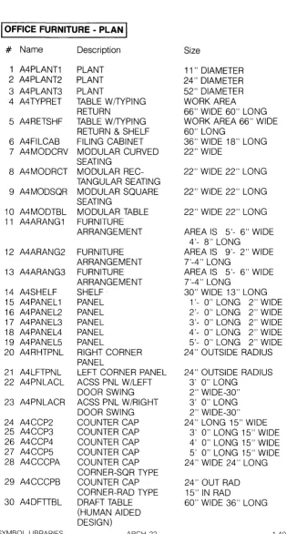
IOFFICE FURNITURE - PLAN
I
#
Name1 A4CHAIR1 2 A4CHAIR2 3 A4CHAIR3 4 A4CHAIR4 5 A4CHAIR5 6 A4CHAIR6 7 A4DESK 8 A4DSKSHF 9 A4DSKCHR 10 A4DSKLFT
11 A4DSKRHT
12 A4RTBL 18 13 A4RTBL48 14 A4RTBL72 15 A4RTBL96 16 A4TBL1 17 A4TBL2 18 A4TBL3 19 A4TBL4 20 A4TBL5 21 A4TBL6 22 A4BTBL 1 23 A4BTBL2 24 A4BTBL3 25 A4BTBL4
26 A4BTBL5
27 A4BTBL6
28 A4CLSTR1
29 A4CLSTR2
30 A4CLSTR3
SYMBOL LIBRARIES Description CHAIR CHAIR CHAIR CHAIR CHAIR CHAIR OESK
DESK SHELF UNIT DESK WITH CHAI R DESK W /LEFT RETURN
DESK W/RIGHT RETURN
Size
22" WIDE 14" LONG 22" WIDE 20" LONG 20" WIDE 20" LONG 20" WIDE 20" LONG 26" WIDE 20" LONG 32" WIDE 24" LONG 72" WIDE 38" LONG 48" WIDE 15" LONG 60" WIDE 30" LONG WORK AREA 60" WIDE 60" LONG WORK AREA 60" WIDE 66" LONG ROUND TABLE 18" DIAMETER ROUND TABLE 48" DIAMETER ROUND TABLE 72" DIAMETER ROUND TABLE 96" DIAMETER TABLE 66" WIDE 30" LONG TABLE 84" WIDE 42" LONG TABLE 108" WIDE 48" LONG TABLE W/4 CHAIRS TABLE: 66" X 30" TABLE W/6 CHAIRS TABLE: 84"
X
42" TABLE W/10 CHAIRS TABLE: 108"X
48" BOAT TABLE 84" WIDE 36" LONG BOAT TABLE 120" WIDE 48" LONG BOAT TABLE TABLE: 14'0" X 60" BOAT TABLE WITH 6 CHAIRS TABLE: 84"X
36"BOAT TABLE WITH 10 CHAIRS
BOAT TABLE WITH 14 CHAIRS
FURNITURE CLUSTER-4 TABLES & 4 CHAIRS FURNITURE CLUSTER-4 OFFICES
FURNITURE CLUSTER-2 OFFICES
ARCH-20
TABLE: 120"X 48"
TABLE: 14'0" X 60"
120" WIDE 120" LONG
AREA: 124"
X
1~4"AREA: 8'10"
X
14'8"I
OFFICE FURNITURE _ PLANI
MENU PREFIX: A4L . . . . __________--1. LAYER #: 6
1 2 3 4 5
0
0
D
~ ~
A4CHAIR1 A4CHAIR2 A4CHAIR3 A4CHAIR4 A4CHAIR5
6 7 8 9 10
j[X
~
0
r===1
0
a
A4CHAIR6 A4DESK A4DSKSHF A4DSKCHR A4DSKLFT
11 12 13 14 15
~
0
0
0
0
A4DSKRH-T A4RTBL18 A4RTBL48 A4RTBL72 A4RTBL96
16 17 18 19 120
0
CJ
[
I
0
1:d
A4TBL 1 A4TBL2 A4TBL3 A4TBL4 A4TBL5
21 22 23 24 25
:0
I
I[
]
(
J
0
A4TBL6 A4BTBL1 A4BTBL2 A4BTBL3 A4BTBL4
26 27
~
29WE
a
~::::J
0A4BTBL5 A4BTBL6 A4CLSTR1 A4CLSTR2 A4CLSTR3
I
OFFICE
FURNITURE - PLANI
# Name Description Size
1 A4PLANT1 PLANT 11 " DIAMETER 2 A4PLANT2 PLANT 24" DIAMETER 3 A4PLANT3 PLANT 52" DIAMETER
4 A4TYPRET TABLE W/TYPING WORK AREA RETURN 66" WIDE 60" LONG 5 A4RETSHF TABLE W (TYPING WORK AREA 66" WIDE
RETURN & SHELF 60" LONG
6 A4FILCAB FILING CABINET 36" WIDE 18" LONG 7 A4MODCRV MODULAR CURVED 22" WIDE
SEATING
8 A4MODRCT MODULAR REC- 22" WIDE 22" LONG TANGULAR SEATING
9 A4MODSQR MODULAR SQUARE 22" WIDE 22" LONG SEATING
10 A4MODTBL MODULAR TABLE 22" WIDE 22" LONG 11 A4ARANG1 FURNITURE
ARRANGEMENT AREA IS 5'- 6" WIDE 4'- 8" LONG
12 A4ARANG2 FURNITURE AREA IS 9'- 2" WIDE ARRANGEMENT 7'-4" LONG
13 A4ARANG3 FURNITURE AREA IS 5'- 6" WIDE ARRANGEMENT 7'-4" LONG
14 A4SHELF SHELF· 30" WIDE 13" LONG 15 A4PANEL 1 PANEL 1'- 0" LONG 2" WIDE 16 A4PANEL2 PANEL 2'- 0" LONG 2" WIDE 17 A4PANEL3 PANEL 3'- 0" LONG 2" WIDE 18 A4PANEL4 PANEL 4'- 0" LONG 2" WIDE 19 A4PANEL5 PANEL 5'- 0" LONG 2" WIDE 20 A4RHTPNL RIGHT CORNER 24" OUTSIDE RADIUS
PANEL
21 A4LFTPNL LEFT CORNER PANEL 24" OUTSIDE RADIUS 22 A4PNLACL ACSS PNL W /LEFT 3' 0" LONG
DOOR SWING 2" WIDE-30" 23 A4PNLACR ACSS PNL W /RIGHT 3' 0" LONG
DOOR SWING 2" WIDE-30" 24 A4CCP2 COUNTER CAP 24" LONG 15" WIDE 25 A4CCP3 COUNTER CAP 3' 0" LONG 15" WIDE 26 A4CCP4 COUNTER CAP 4' 0" LONG 15" WIDE 27 A4CCP5 COUNTER CAP 5' 0" LONG 15" WIDE 28 A4CCCPA COUNTER CAP 24" WIDE 24" LONG
CORNER-SQR TYPE
29 A4CCCPB COUNTER CAP 24" OUT RAD CORNER-RAD TYPE 15" IN RAD
30 A4DFTIBL DRAFT TABLE 60" WIDE 36" LONG (HUMAN AIDED
DESIGN)
[image:57.397.42.357.10.596.2]I
OFFICE FURNITURE - PLANI
MENU PREFIX: A4L - . _ _ _ _ _ _ _ _ _ _ ~. LAYER #: 6
1 2 3 4 5
~
~
Q
[b
~
A4PLANT1 A4PLANT2 A4PLANT3 A4TYPRET A4RETSHF
6 7 8 9 10
D
E>
EJ
OJ 0
A4FILCAB A4MODCRV A4MODRCT A4MODSQR A4MODTBL
11 12 13 14 15
Bflj
1m
d1
I
I
~A4ARANG1 A4ARANG2 A4ARANG3 A4SHELF A4PANEL 1
16 17 18 19 20
iii I :Ii I :Ii I ;;: I
{
A4PANEL2 A4PANEL3 A4PANEL4 A4PANELS A4RHTPNL
21 22 23 24 25
~
J\
f1
D
t
I
A4LFTPNL A4PNLACL A4PNLACR A4CCP2 A4CCP3
26 27 28 29 30
t
I
t
]
CJ
~
~
A4CCP4 A4CCPS A4CCCPA A4CCCPB A4DFTTBL
!PLUMBING FIXTURE ELEVATIONSI
#
Name Description Size1 A5LTWC1 LOW TANK WATERCLOSET 30" WIDE 36" HIGH (SIDE VIEW)
2 A5LTWC2 LOW TANK WATER CLOSET 18" WIDE 6" HIGH (FRONT VIEW)
3 A5ATWC1 ATIACHED TANK WATER 30" WIDE 32" HIGH CLOSET
(SIDE VIEW)
4 A5ATWC2 ATIACHED TANK WATER 24" WIDE 32" HIGH CLOSET (FRONT VIEW(
5 A5WFWC1 WALL FLSH VALV WTR 28" WIDE 18" HIGH CLOSET (SIDE VIEW)
6 A5WFWC2 WALL FLSH VALV WTR 17" WIDE 18" HIGH CLOSET (FRONT VIEW)
7 A5SINK1 LAVATORY (SIDE VIEW) 21" WIDE 32" HIGH 8 A5SINK2 LAVATORY (FRONT VIEW) 26" WIDE 32" HIGH 9 A5SINK3 LAVATORY (SIDE VIEW) 20" WIDE 36" HIGH 10 A5SINK4 LAVATORY (FRONT VIEW) 20" WIDE 36" HIGH 11 A5SINK5 LAVATORY (SIDE VIEW) 17" WIDE 36" HIGH 12 A5SINK6 LAVATORY (SIDE VIEW) 13" WIDE 37" HIGH 13 A5SINK7 LAVATORY (FRONT VIEW) 21" WIDE 37" HIGH 14 A5PED1 PEDESTAL (SIDE VtEW) 23" WIDE 32" HIGH 15 A5PED2 PEDESTAL (FRONTVIEW) 15" WIDE 32" HIGH 16 A5WLHNG1 WALL HUNG URINAL 16" WIDE 36" HIGH
(SIDE VIEW)
17 A5WLHNG2 WALL HUNG URINAL 16" WIDE 36" HIGH (FRONT VIEW)
18 A5URINL 1 URINAL (SIDE VIEW) 20" WIDE 40" HIGH 19 A5URINL2 URINAL (FRONT VIEW) 16" WIDE 40" HIGH 20 A5URINL3 THROUGH URINAL 14" WIDE 25" HIGH
(SIDE VIEW)
21 A5URINL4 THROUGH URINAL 64" WIDE 25" HIGH (FRONT VIEW)
22 A5STALL 1 URINAL STALL (SIDE VIEW) 16" WIDE 39" HIGH 23 A5STALL2 URINAL STALL (FRONT 20" WIDE 39" HIGH
VIEW)
24 A5STALL3 URINAL STALL (FRONT 21" WIDE 39" HIGH VIEW)
25 A5TANK1 OVERHEAD TANK (SIDE 16" WIDE 48" HIGH VIEW)
26 A5TANK2 OVERHEAD TANK (FRONT 19" WIDE 48" HIGH VIEW)
27 A5TANK3 TANK (FRONT VIEW) 13" WIDE 35" HIGH 28 A5DRINK1 DRINKING FOUNTAIN 14" WIDE 36" HIGH
(SIDE VIEW)
29 A5DRINK2 DRINKING FOUNTAIN 14" WIDE 36" HIGH (FRONT VIEW)
30 A5CABSEC CABINET (SIDE VIEW) 6" WIDE 27" HIGH
I
PLUMBING FIXTURE ELEVATIONS] MENU PREFIX: ASL . . . ___________- - - ' . LAYER #: 7
10
20
3 4 5D
V
[ J
.0
1]1-
'(x x
A5L TWC1 A5L TWC2 A5A TWC1 A5A TWC2 A5WFWC1
6 7 8 9
y
1O?
Q
Y
y
x
A5WFWC2 A5SINK1 A5SINK2 A5SINK3 A5SINK4 11
T
12r
13?
14u
15li
A5SINK5 A5SINK6 A5SINK7 A5PED1 A5PED2
16 17
9
18~
199
20Y
xb
A5WLHNG1 A5WLHNG2 A5URINL 1 A5URINL2 A5URINL3
21 22
Y
23
9
249
25~
~
~
x
A5URINL4 A5STALL1 A5STALL2 A5STALL3 A5TANK1
26
J
27 28 29 30
II
r
.1
x~
A5TANK2 A5TANK3 A5DRINK1 A5DRINK2 A5CABSEC
I
PLUMBING FIXTURE ELEVATIONSI
#
Name Description Size1 A5CAB1 MED CABINET 20" WIDE 26" HIGH (FRONT VIEW)
2 A5CAB2 MED CABINET 16" WIDE 22" HIGH (FRONT VIEW)
3 A5CAB3 MED CABINET 14" WIDE 20" HIGH (FRONT VIEW)
4 A5S0AP1 SOAP RECEPTACLE 8" WIDE 6" HIGH 5 A5S0AP2 SOAP RECEPTACLE 8" WIDE 4" HIGH 6 A5S0AP3 SOAP RECEPTACLE 4" WIDE 4" HIGH 7 A5GBAR1 GRAB BAR 12" LONG
8 A5GBAR2 GRAB BAR 10" LONG 9 A5GBAR3 GRAB BAR 8"LONG
10 A5PLUG1 PLUG OR SWITCH OUTLET 8" WIDE 4" HIGH 11 A5PLUG2 PLUG OR SWITCH OUTLET 4" WIDE 4" HIGH 12 A5PLUG3 PLUG OR SWITCH OUTLET 4" WIDE 2" HIGH 13 A5TBAR1 TOWEL BAR 18" LONG
14 A5TBAR2 TOWEL BAR 24" LONG 15 A5TBAR3 TOWEL BAR 30" LONG 16 A5TBAR4 TOWEL BAR 36" LONG
17 A5TUB BATHTUB (SIDE VIEW) 64" WIDE 18" HIGH 18 A5TUBSEC BATHTUB (FRONT VIEW) 34" WIDE 18" HIGH 19 A5DSPOSL GARBG DISPOSAL (FRONT 22" WIDE 27" HIGH
VIEW)
20 A5KSINK1 KITCHEN SINK 21" WIDE 36" HIGH (FRONT VIEW)
21 A5KSINK2 KITCHEN SINK (SIDE VIEW) 16" WIDE 36" HIGH 22 A5KSINK3 KITCHEN SINK
(FRONT VIEW) 20" WIDE 36" HIGH
23 A5KSINK4 KITCHEN SINK
(FRONT VIEW) 27" WIDE 36" HIGH
24 A5KSINK5 KITCHEN SINK (SIDE VIEW) 26" WIDE 48" HIGH 25 A5KSINK6 KITCHEN SINK (SIDE VIEW) 34" WIDE 36" HIGH 26 A5TRAY1 WASH TRAY (SIDE VIEW) 32" WIDE 42" HIGH 27 A5TRAY2 WASH TRAY (FRONT VIEW) 30" WIDE 34" HIGH 28 A5TRAY3 WASH TRAY (SIDE VIEW) 28" WIDE 44" HIGH 29 A5TRAY4 WASH TRAY (FRONT VIEW) 27" WIDE 35" HIGH 30 A5PAN SHOWER PAN (SIDE VIEW) 40" WIDE 10" HIGH
I
PLUMBING FIXTURE ELEVATIONSI
MENU PREFIX: ASL - . _ _ _ _ _ _ _ _ _ _ _ ----1. LAYER #: 7
10
20
3 4 50
0
,CJ
A5CAB1 A5CAB2 A5CAB3 A5S0AP1 A5S0AP2
6 7 8 9 10
0
c:::::::;
,c::::;
c=J
CJ
A5S0AP3 A5GBAR1 A5GBAR2 A5GBAR3 A5PLUG1
11 12 13 14 15
0
D
f.
),
) If J A.5PLUG,2 A5PLUG3 A5TBARI A5TBAR2 A5TBAR316 17 18 19 20
0
7J
Y
If
JII
J
)(
A5TBAR4 A5TUB A5TUBSEC A5DSPOSL A5KSINK1
21 22
23
T
242F-T
r
T
A5KSINK2 A5KSINK3 A5KSINK4 A5KSINK5 A5KSINK6
26 27 28 29 30
~
9
y
Y
) - -w-J
A5TRAY1 A5TRAY2 A5TRAY3 A5TRAY4 A5PAN
I
LIGHTINGI
#
Name1 A6FL2X2 2 A6FLS2X2
3 A6FL2X4 4 A6FLS2X4
5 A6FL3X3 6 A6FLS3X3
7 A6FL4X4 8 A6FLS4X4
9 A6FL1X4 10 A6FLS1X4
11 A6FL 1 X8 12 A6FLS1X8
13 A6FL6X8 14 A6FS6X8
15 A6FL6X4 16 A6FS6X4
17 A6STRIP4
18 A6STRIP8
19 A6TB2X2 20 A6TBS2X2
21 A6TB2X4 22 A6TBS2X4
23 A6TB3X3 24 A6TBS3X3
25 A6TB4X4 26 A6TBS4X4
27 A1POLELT 28 A1 LOTLT1 29 A1 LOTLT2 30 A1 LOTLT4
SYMBOL LIBRARIES
Description
FLUORESCENT LIGHT SPECIAL FLUORESCENT LIGHT
FLUORESCENT LIGHT SPECIAL FLUORESCENT LIGHT
FLUORESCENT LIGHT SPECIAL FLUORESCENT LIGHT
FLUORESCENT LIGHT SPECIAL FLUORESCENT LIGHT
FLUORESCENT LIGHT SPECIAL FLUORESCENT LIGHT
FLUORESCENT LIGHT SPECIAL FLUORESCENT LIGHT
FLUORESCENT LIGHT SPECIAL FLUORESCENT LIGHT
FLUORESCENT LIGHT SPECIAL FLUORESCENT LIGHT
Size
24" WIDE 24" LONG 24" WIDE 24" LONG
24" WIDE 48" LQNG 24" WIDE 48" LONG
36" WIDE 36" LONG 36" WIDE 36" LONG
48" WIDE 48" LONG 48" WIDE 48" LONG
12" WIDE 48" LONG 12" WIDE 48" LONG
12" WIDE 96" LONG 12" WIDE 96" LONG
6" WIDE 96" LONG 6" WIDE 96" LONG
6" WIDE 48" LONG 6" WIDE 48" LONG
BARE LAMP FLUORESCENT 48" LONG STRP
BARE LAMP FLUORESCENT 96" LONG STRP
T-BAR FLUORESCENT LIGHT 24" WIDE 24" LONG SPECIAL T-BAR 24" WIDE 24" LONG FLUORESCENT
T-BAR FLUORESCENT LIGHT 24" WIDE 48" LONG SPECIAL T-BAR FLUORES- 24" WIDE 48" LONG CENT LIGHT
T-BAR FLUORESCENT LIGHT 36" WIDE 36" LONG SPECIAL T-BAR FLUORES- 36" WIDE 36" LONG CENT LIGHT
T-BAR FLUORESCENT LIGHT 48" WIDE 48" LONG SPECIAL T-BAR FLUORES- 48" WIDE 48" LONG CENT LIGHT
STREET POLE LIGHT PARKING LOT LIGHT PARKING LOT LIGHT PARKING LOT LIGHT
ARCH-28
6" DIAMETER 6" WIDE 6" LONG 6" WIDE 6" LONG 6" WIDE 6" LONG
I
LIGHTINGI
MENU PREFIX:A6, A1L . . . ___- - ' _ LAYER #: 4
1 2 3 4 5
0
IS]
D
~
D
A6FL2X2
A6FLS2X2
A6FL2X4
A6FLS2X4
A6FL3X3
6 7 8 9 10
[SJ
D
[S]
0
~
A6FLS3X3
A6FL4X4
A6FLS4X4
A6FL1X4
A6FLS1X4
11 12 13 14 15
~ ~ ~
!
~
A6FL 1 X8
A6FLS1 X8
A6FL6X8
A6FS6X8
A6FL6X4
16 17 18
I
19 20
~
I
0
IS]
A6FS6X4
A6STRIP4
A6STRIP8
A6TB2X2
A6TBS2X2
21 22 23 24 25
D
~
D
[SJ
D
A6TB2X4
A6TBS2X4
A6TB3X3
A6TBS3X3
A6TB4X4
26 27 28 29 30
[S]
~
0D D0D
DD
0
DD
A6TBS4X4
A1POLELT
A1LOTLT1
A1LOTLT2
A1LOTLT4
I
ELECTRICALI
#
Name Description1 E3SINGL SINGLE RECEPTACLE OUTLET
2 E3DUPLX DUPLEX RECEPTACLE OUTLET
3 E3QUAD QUADRAPLEX RECEPTACLE OUTLET
4 E3SPLTWR DUPLEX RECEPTACLE OUTLET-SPLIT WIRED 5 E3SINGLS SINGLE SPECIAL-PURPOSE
RECEPTACLE OUTLET 6 E3DUPLXS DUPLEX SPECIAL-PURPOSE
RECEPTACLE OUTLET 7 E3RANGE RANGE OUTLET 8 E3GNPURP GENERAL PURPOSE
OUTLET
9 E3SP SINGLE-POLE SWITCH 10 E3DP DOUBLE-POLE SWITCH 11 E3SINGLF FLOOR SINGLE
RECEPTACLE OUTLET 12 E3FLSPCL FLOOR SPECIAL-PURPOSE
OUTLET
13 E3DUPLXF FLOOR DUPLEX RECEPTACLE OUTLET 14 E3FLRPRI FLOOR TELEPHONE
OUTLET-PRIVATE 15 E3FLRPUB FLOOR TELEPHONE
OUTLET-PUBLIC
16 E3PHONE TELEPHONE WALL OUTLET 17 E31NTRCM INTERCOM WALL OUTLET 18 E31NTRWM INTERCOM HANDSET-WALL
MOUNTED
19 E3FALRMS FIRE ALARM-SINGLE HORN 20 E3FALRMD FIRE ALARM-DOUBLE HORN 21 E3SPKRWM EXTERIOR SPEAKER-WALL
MOUNTED
22 E3SPKH EXTERIOR SPEAKER 23 E3HANGER HANGER RECEPTACLE 24 E33WAY 3 WAY SWITCH
25 E3RWAY 4 WAY SWITCH
26 E3KEYOP KEY OPERATED SWITCH 27 E3PLTLMP SWITCH & PILOT LAMP 28 E3SWSNGL SWITCH & SINGLE
RECEPTACLE 29 E3SWDPLX SWITCH W /DUPLEX
RECEPTACLE
30 E3RCSLMP RECESSED INCANDESCENT LAMP OUTLET
I
ELECTRICAL
I
~ENU PREFIX: E3L . . . . ____. . . LAYER #: 4
1 2 3 4 5
-e
~
C@
~
-@
E3SINGL E30UPLX E3QUAO E3SPL TWR E3SINGLS
6 7 8 9 10
c@
~
-@
5
52
E30UPLXS E3RANGE E3GNPURP E3SP E30P
11 12 13 14 15
[~]
~ ~
@]
~
E3SINGLF E3FLSPCL E30UPLXF E3FLRPRI E3FLRPUB
16 17 18
19
~
20
~
kJ
~
~
E3PHONE E31NTRCM E31NTRWM E3FALRMS E3FALRMD
21 22 23 24 25
~
@ -0
53
54
E3SPKRWM E3SPKR E3HANGER E33WAY E34WAY
26 27 28
S
29S
305K
5p
cp
~
®
E3KEYOP E3PL TLMP E3SWSNGL E3SWDPLX E3RCSLMP
I
ELECTRICALI#
Name Description1 E3SRFLMP SURFACE OR PENDANT INCANDESCENT LAMP OUTLET
2 E3JUNCBX JUNCTION BOX 3 E3TRMCAB TERMINAL CABINET 4 E3EQPCAB EQUIPMENT CABINET 5 E3PNLBRD PANEL BOARD 6 E3GROUND GROUND ROD 7 E3MOTOR1 MAGNETIC MOTOR
STARTER-WALL MOUNTED 8 E3MOTOR2 MAGNETIC MOTOR
STARTER-WALL MOUNTED 9 E3MOTOR3 MOTOR WITH DISCONNECT 10 E3MOTOR4 MAGNETIC MOTOR
STARTER-CEILING MOUNTED
11 E3MOTOR5 MAGNETIC MOTOR STARTER-WITH DISCONNECT 12 E3EXIT1 EXIT LIGHT 13 E3EXIT2 EXIT LIGHT 14 E3EXIT3 EXIT LIGHT
15 E3EXIT4 EXIT LIGHT - WALL MOUNTED
16 E3EXIT5 EXIT LIGHT - WALL MOUNTED
17 E3EXIT6 EXIT LIGHT - WALL MOUNTED
18 E3RSRUP CONDUIT RISER-UP 19 E3RSRDWN CONDIUT RISER-DOWN 20 E3SIN SINGLE CONDUCTOR 21 E3SIN1 N SINGLE CONDUCTOR-1
NEUTRAL
22 E3DBL DOUBLE CONDUCTOR 23 E3DBL1N DOUBLE CONDUCTOR-1
NEUTRAL
24 E3DBL2N DOUBLE CONDUCTOR-2 NEUTRAL
25 E3TRPL TRIPLE CONDUCTOR 26 E3TRP1N TRIPLE CONDUCTOR-1
NEUTRAL
27 E3TRPL3N TRIPLE CONDUCTOR-3 NEUTRAL
28 E3PSHBUT PUSHBUnON 29 E3BUZZER BUZZER 30 E3BELL BELL
I
ELECTRICALI
MENU PREFIX: E3L . . . _ _ _ _ - - - - ' . LAYER #: 4
1 2 3 4
5~1
0
@
1
I
r0/~j
E3SRFLMP E3JUNCBX E3TRMCAB E3EQPCAB E3PNLBRD
6 7 8 9 10
1
)(
~
~
Q)
~
E3GROUND E3MOTOR1 E3MOTOR2 E3MOTOR3 E3MOTOR4
11 12 13 14 15
~
~ ~ ~+--f
® ® ®
E3MOTOR5 E3EXIT1 E3EXIT2 E3EXIT3 E3EXIT4
16 17 18 19 20
----?- ~
f f
0)
~
I
E3EXIT5 E3EXIT6 E3RSRUP E3RSRDWN E3SIN
21 22 23 24 25
/x/
Ixl
III
/ /x/ /
/1/
E3SIN1 N E3DBL E3DBL 1 N E3DBL2N E3TRPL
26 27 28 29 30
I
Ixl I
I / Ix/ I /
~
\[]
OJ
E3TRPL1N E3TRPL3N E3PSHBUT E3BUZZER E3BELL
HEATING, VENTILATION
&
AIR CONDITIONING
SYMBOL LIBRARY
.... ·caCi
SYMBOL TRANSFER PROGRAM
This utility program is used to quickly transfer symbols individually or in groups from one layer to another.
Note: It does not duplicate symbols--it only moves them.
GETTING STARTED (HARD DISK SYSTEM)
COPY all of the Symbol Library diskettes onto drive C, (See the DOS Primer Chapter of your manual for instructions).
GETTING STARTED (TWO DRIVE SYSTEM)
COPY the file CPSYMTRN.EXE onto the diskette you plan