Electrical and Computer Engineering Publications
Electrical and Computer Engineering
2015
Deep brain transcranial magnetic stimulation using
variable “Halo coil” system
Y. Meng
Iowa State University
Ravi L. Hadimani
Iowa State University, [email protected]
Lawrence J. Crowther
Iowa State University, [email protected]
Z. Xu
Iowa State University
J. Qu
Iowa State University
Follow this and additional works at:
http://lib.dr.iastate.edu/ece_pubs
Part of the
Electromagnetics and Photonics Commons
, and the
Engineering Physics Commons
The complete bibliographic information for this item can be found at
http://lib.dr.iastate.edu/
ece_pubs/50
. For information on how to cite this item, please visit
http://lib.dr.iastate.edu/
howtocite.html
.
Deep brain transcranial magnetic stimulation using variable “Halo coil”
system
Abstract
Transcranial Magnetic Stimulation has the potential to treat various neurological disorders non-invasively and safely. The “Halo coil” configuration can stimulate deeper regions of the brainwith lower surface to deep-brain field ratio compared to other coil configurations. The existing “Halo coil” configuration is fixed and is limited in varying the site of stimulation in the brain. We have developed a new system based on the current “Halo coil” design along with a graphicaluser interface system that enables the larger coil to rotate along the
transverse plane. The new system can also enable vertical movement of larger coil. Thus, this adjustable “Halo coil” configuration can stimulate different regions of the brain by adjusting the position and orientation of the larger coil on the head. We have calculated magnetic and electric fields inside a MRI-derived heterogeneous head model for various positions and orientations of the coil. We have also investigated the mechanical and thermal stability of the adjustable “Halo coil” configuration for various positions and orientations of the coil to ensure safe operation of the system.
Keywords
Ames Laboratory, Coils, Brain, Electrical field, Lorentz group, Magnetic fields
Disciplines
Electromagnetics and Photonics | Engineering Physics
Comments
The following article appeared in J. Appl. Phys. 117, 17B305 (2015) and may be found athttp://dx.doi.org/ 10.1063/1.4913937.
Rights
Copyright 2015 American Institute of Physics. This article may be downloaded for personal use only. Any other use requires prior permission of the author and the American Institute of Physics.
Deep brain transcranial magnetic stimulation using variable “Halo coil” system
Y. Meng, R. L. Hadimani, L. J. Crowther, Z. Xu, J. Qu, and D. C. Jiles
Citation: Journal of Applied Physics 117, 17B305 (2015); doi: 10.1063/1.4913937 View online: http://dx.doi.org/10.1063/1.4913937
View Table of Contents: http://scitation.aip.org/content/aip/journal/jap/117/17?ver=pdfcov
Published by the AIP Publishing
Articles you may be interested in
Characteristics of bowl-shaped coils for transcranial magnetic stimulation
J. Appl. Phys. 117, 17A318 (2015); 10.1063/1.4914876
Transcranial magnetic stimulation of mouse brain using high-resolution anatomical models
J. Appl. Phys. 115, 17B303 (2014); 10.1063/1.4862217
Transcranial magnetic stimulation: Improved coil design for deep brain investigation
J. Appl. Phys. 109, 07B314 (2011); 10.1063/1.3563076
A method for estimation of stimulated brain sites based on columnar structure of cerebral cortex in transcranial magnetic stimulation
J. Appl. Phys. 105, 07B303 (2009); 10.1063/1.3068631
Comparison of current distributions in electroconvulsive therapy and transcranial magnetic stimulation
J. Appl. Phys. 91, 8730 (2002); 10.1063/1.1454987
Deep brain transcranial magnetic stimulation using variable “Halo coil”
system
Y. Meng, R. L. Hadimani,a)L. J. Crowther, Z. Xu, J. Qu, and D. C. Jiles
Department of Electrical and Computer Engineering, Iowa State University, Ames, Iowa 50011, USA
(Presented 7 November 2014; received 22 September 2014; accepted 28 October 2014; published online 4 March 2015)
Transcranial Magnetic Stimulation has the potential to treat various neurological disorders non-invasively and safely. The “Halo coil” configuration can stimulate deeper regions of the brain with lower surface to deep-brain field ratio compared to other coil configurations. The existing “Halo coil” configuration is fixed and is limited in varying the site of stimulation in the brain. We have developed a new system based on the current “Halo coil” design along with a graphical user inter-face system that enables the larger coil to rotate along the transverse plane. The new system can also enable vertical movement of larger coil. Thus, this adjustable “Halo coil” configuration can stimulate different regions of the brain by adjusting the position and orientation of the larger coil on the head. We have calculated magnetic and electric fields inside a MRI-derived heterogeneous head model for various positions and orientations of the coil. We have also investigated the me-chanical and thermal stability of the adjustable “Halo coil” configuration for various positions and orientations of the coil to ensure safe operation of the system.VC 2015 AIP Publishing LLC.
[http://dx.doi.org/10.1063/1.4913937]
INTRODUCTION
Transcranial magnetic stimulation (TMS) is a painless and non-invasive neuromodulation technique based on the principles of magnetic induction.1,2 TMS has been used to study brain function and is being investigated as a possible treatment for numerous brain disorders.4 The technique al-ready shows good efficacy for the treatment of major depres-sive disorder.3 We have previously reported a “Halo coil” configuration which can stimulate deeper regions of the human brain, but the configuration was fixed so that only a single site in the brain has a lower surface to deep-brain field ratio compared to other coil configurations.5 Now, we have built a variable “Halo coil” configuration with a circular coil fixed on top of the head and with vertical and rotational movement of the larger coil to selectively stimulate different regions of the brain. During the stimulation, we used two stimulators to send AC current signals to two coils. One stim-ulator sends an AC current with a frequency of 2.5 kHz and an amplitude of 2500 A to the circular coil. The other stimula-tor sends AC current with a frequency of 2.5 kHz and an am-plitude of 5000 A to the larger coil. We have also conducted thermal and mechanical analysis of the system to ensure its feasibility and stability. A graphical user interface (GUI) sys-tem has been built that accurately controls the movement and rotation of the larger coil using an Arduino microcontroller.
MODELING OF ELECTRIC AND MAGNETIC FIELD
We have used SEMCAD X (SPEAG, Swiss) finite ele-ment software to calculate the electric and magnetic fields generated by the fixed circular coil positioned at the vertex of the head with different orientations of the larger coil. An
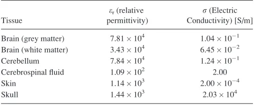
AC current with a frequency of 2.5 kHz and an amplitude of 2500 A was applied to the circular coil which is comparable to the pulse signal generated by a biphasic commercial TMS stimulator with 50% power intensity, and a current signal of the same frequency but with an amplitude of 5000 A was applied to the large coil.5We have used an anatomically re-alistic human head model with different electrical properties assigned to each tissue of the brain.6These parameters are shown in TableI.7
The calculation of magnetic field was based on the Biot-Savart law as shown in the following equation:8
A0ð Þ ¼r
l0
4p
ð
X J0ð Þr0 jrr0jdr
0: (1)
The vector potential A is decoupled from the electric field E which is calculated using Eq. (2) where rEs¼0
(solenoidal) andr Ei¼0 (irrotational)
E¼ jxAþ ru¼EsþEi: (2)
The magneto-quasi-static calculation is described by the following equation:
[image:4.612.314.562.638.741.2]r rru¼jxr ðrA0Þ: (3)
TABLE I. Values of dielectric properties at 2.5 kHz.
Tissue
er(relative permittivity)
r(Electric Conductivity) [S/m]
Brain (grey matter) 7.81104 1.04101
Brain (white matter) 3.43104 6.45102
Cerebellum 7.84104 1.24101
Cerebrospinal fluid 1.09102 2.00
Skin 1.14103 2.00104
Skull 1.44103 2.03104
a)Author to whom correspondence should be addressed. Electronic mail:
0021-8979/2015/117(17)/17B305/4/$30.00 117, 17B305-1 VC2015 AIP Publishing LLC
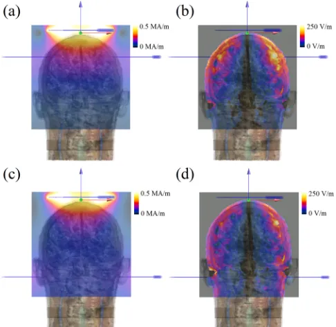
Figs.1(a)–1(d)show the difference in electric and magnetic fields generated in the head for different vertical positions of the large coil. When comparing Figs.1(b)and1(d), it shows that the electric field in Fig.1(b)is higher than that in Fig. 1(d). However, the electric field in lower part of head model is higher in Fig.1(b)than in Fig.1(d), which is enhanced by the position of the large coil. These modeling results show the evidence that the larger coil enhances the electric and magnetic fields at the deeper regions of the brain by reducing the decay of field generated by the smaller circular coil which is fixed on the top of head. Thus, different positions of larger coil enable stimulation of different deeper regions of the human brain and helps clinicians to vary the site of stim-ulation according to the disorder that is being treated.
Fig.2shows the induced electric field in the anatomical heterogeneous head model with the rotational movement of the larger coil. According to Figs.2(b)and2(d), the position of the peak value of the electric field was different according to different positions of the larger coil and the peak value of electric field was approximately 250 V/m which is larger than the threshold electric field of 150 V/m, reported by Marchet al.9and 120 V/m by Rosanova et al.10Therefore, rotation of the larger coil also reduces the decay of electric and magnetic field generated by the small circular coil simi-lar to vertical movement.
MAGNETIC (LORENTZ) FORCE RESPONSE
COMSOL Multiphysics (Los Angeles, CA, USA) was used for magnetic force analysis. A 5000 A DC current was assigned in both coils to evaluate the maximum forces induced on the variable “Halo coil” system. Any forces experienced by the coils will be transferred to the insulation
and thus the yield strength of insulation should be higher than the Lorentz forces exerted by the magnetic fields gener-ated by the coils. The yield strength of copper is 70 MPa (Ref. 11) and the ultimate tensile strength of the insulation, Nylon is 125 MPa.12 The Lorentz force density in the coil can be calculated by Eq. (4), where J (A/m) is the current density and B (T) is the magnetic flux density. In this study, we used 3D models where J (A/m3) is the current density and i¼x, y, z
fi¼JB: (4)
The calculated Lorentz force density f (N/m3) is shown in Fig.3for two extreme conditions for our system. The larger coil is rotated þ30 and the distance between the centers of two coils is 5 cm and 15 cm. Fig. 3(a) is the top view and Fig.3(b)is the side view for a distance of 5 cm between the coils. In Figs.3(c)and3(d), the distance between the centers of two coils is 15 cm, i.e., Fig. 3(c)is the top view and Fig. 3(d)is the side view.
The arrows in the picture show the direction of Lorentz forces and their lengths indicate the magnitude of that force density. In the side view, the majority of Lorentz force den-sity was parallel to the direction of vertical movement of the large coil. The maximum Lorentz force was 335.01 MN/m3. The equivalent stress on the larger coil was 3.35 MPa. The coils are made of copper with a yield strength of 70 MPa and covered with Nylon, which has a yield/ultimate tensile strength of 125 MPa. Thus, the stress due to the Lorentz forces in the larger coil was significantly smaller than the yield strength of copper and Nylon. The system is therefore be mechanically stable and can withstand the expected Lorentz forces. However, the cyclic loading conditions, which can occur in repetitive TMS, have not been analyzed.
FIG. 1. Magnetic field ((a) and (c)) and electric field ((b) and (d)) generated in the anatomically realistic human head model for different vertical posi-tions of the large coil. In figures (a) and (b), the distance between two coils is 5 cm. In figures (c) and (d), the distance between two coils is 15 cm.
FIG. 2. Magnetic field ((a) and (c)) and electric field ((b) and (d)) generated in the anatomically realistic human head model for different rotational angles of the large coil. In figures (a) and (b), the coil is rotatedþ30. In fig-ures (c) and (d), the coil is rotated30.
17B305-2 Menget al. J. Appl. Phys.117, 17B305 (2015)
[image:5.612.53.296.482.718.2]THERMAL ANALYSIS
The temperature in the coils was another important fac-tor in the system because of the high amplitude of the current induced in the coil. This can generate a large amount of heat in the coil due to Joule’s law (Q¼I2Rt). The limit of sur-face temperature for electrical medical equipment has been specified by General Standard IEC 60601-2-37, which is 50C in air and 43C at the surface of the body.13Thus, the modeling of heat was focused on the duration of the stimula-tion when either of the coils reached 50C. The incompressi-ble Navier-Stokes heat equation from the COMSOL Heat Transfer module was used to model the thermal changes in the coil system under TMS therapy conditions, as shown in the following equation:
qCp@T
@t þCpu rT¼ r ðkrTÞ þQ; (5)
whereqis the fluid density,Cpis the fluid heat capacity,Tis the temperature,uis the velocity field of the fluid,k is the thermal diffusivity of the material, andQis external source heating.14According to the modeling results shown in Fig.4, after stimulation for 231 s, the small circular coil, which is placed on the top on patient’s head, reached 50.04C. Additionally, the vertical position and the rotational move-ment of the larger coil did not have a significant effect on the heat generated in the two coils as all positions and orienta-tions demonstrated similar results of approximately 50C in the smaller coil after 231 s of stimulation.
GUI SYSTEM
A GUI was developed in Java to control the movement and rotation of the larger coil with a computer via an
[image:6.612.59.291.58.298.2]Arduino microcontroller, as shown in Fig.5. The left portion of the interface is the control panel, which has two buttons to control the vertical movement of large coil by a linear actua-tor. The range of vertical movement is5 cm toþ5 cm com-pared to its origin with a step size of 1 cm. It also has two buttons to control the rotation by a servo motor. The range of rotation is 30 toþ30 compared to its origin with a step size of 5. The right portion of the interface shows the mod-eling results of electric and magnetic field for the selected position of the large coil. These images will show the distri-bution of magnetic and electric field, which will indicate the site of stimulation with a field larger than the threshold or peak field for the selected position of the large coil.
[image:6.612.318.560.59.315.2]FIG. 3. The result of force analysis between the two coils with larger coil rotated atþ30. In (a) and (b), the distance between the centers of two coils is 5 cm, where (a) is the top view and (b) is the side view. In (c) and (d), the distance between the centers of two coils is 15 cm, where (c) is the top view and (d) is the side view.
FIG. 4. The result of thermal analysis of two coils with larger coil rotated at þ30. In (a) and (b), the distance between the centers of two coils is 5 cm, where (a) is the top view and (b) is the side view. In (c) and (d), the distance between the centers of two coils is 15 cm, where (b) is the top view and (d) is the side view.
FIG. 5. The graphic user interface (GUI).
[image:6.612.317.558.560.748.2]CONCLUSION
TMS is a novel non-invasive and safe treatment for various neurological disorders. In our present work, we have designed and developed a variable “Halo coil” system that can achieve deep brain stimulation at specific treat-ment areas with the vertical and rotational movetreat-ment of the larger coil in the “Halo coil” system. We have also deve-loped a GUI system to control the movement precisely via a computer. The modeling results of magnetic and electric field confirm that our design can stimulate different parts of human brain. The modeling result of Lorentz forces show that the magnetic forces in coils do not exceed the yield strengths of the coil material and casing in the system. The modeling results of Joule heating showed that the treatment time of 231 s will heat the coil to a temperature of 50.04C. Thus, for longer treatment times, an active cool-ing system uscool-ing external air or water circulation should be considered.
ACKNOWLEDGMENTS
This work was supported by the Carver Charitable Trust and the Barbara and James Palmer Endowment at the Department of Electrical and Computer Engineering, Iowa State University.
1A. T. Barker, R. Jalinous, and I. L. Freeston,Lancet325, 1106 (1985). 2
P. J. Basser and B. J. Roth,Med. Biol. Eng. Comput.29, 261 (1991). 3
S. Rossi, M. Hallett, P. M. Rossini, and A. Pascual-Leone, Clin. Neurophysiol.120, 2008 (2009).
4M. S. George, S. H. Lisanby, D. Avery, W. M. McDonald, V. Durkalski, M.
Pavlicova, B. Anderson, Z. Nahas, P. Bulow, P. Zarkowski, P. E. Holtzheimer, T. Schwartz, and H. A. Sackeim,Arch. Gen. Psychiatry67, 507 (2010). 5
L. J. Crowther, P. Marketos, P. I. Williams, Y. Melikhov, D. C. Jiles, and J. H. Starzewski,J. Appl. Phys.109, 07B314 (2011).
6A. Christ, W. Kainz, E. G. Hahn, K. Honegger, M. Zefferer, E. Neufeld,
W. Rascher, R. Janka, W. Bautz, J. Chen, B. Kiefer, P. Schmitt, H.-P. Hollenbach, J. Shen, M. Oberle, D. Szczerba, A. Kam, J. W. Guag, and N. Kuster,Phys. Med. Biol.55, N23 (2010).
7P. A. Hasgall, F. Di Gennaro, C. Baumgartner, E. Neufeld, M. C.
Gosselin, D. Payne, A. Klingenb€ock, and N. Kuster, “IT’IS Database for thermal and electromagnetic parameters of biological tissues,” Version 2.5, August 1st, 2014, available atwww.itis.ethz.ch/database.
8
L. J. Crowther, K. Porzig, R. L. Hadimani, H. Brauer, and D. C. Jiles, IEEE Trans. Magn.48, 4058 (2012).
9
S. D. March, S. McAtee, M. Senter, K. Spoth, D. R. Stiner, L. J. Crowther, R. L. Hadimani, and D. C. Jiles, “Focused and deep brain magnetic stimu-lation using new coil design in mice,” 2013 6th Int. IEEE/EMBS Conf. Neural Eng., Nov. 2013, pp. 125–128.
10
M. Rosanova, A. Casali, V. Bellina, F. Resta, M. Mariotti, and M. Massimini,J. Neurosci.29, 7679 (2009).
11L. J. Crowther, K. Porzig, R. L. Hadimani, H. Brauer, and D. C. Jiles,
IEEE Trans. Magn.49, 3426 (2013). 12
H. Mahfuz, A. Adnan, V. K. Rangari, M. M. Hasan, S. Jeelani, W. J. Wright, and S. J. DeTeresa,Appl. Phys. Lett.88, 083119 (2006). 13
IEC IS 60601: Medical Electrical Equipment—Part 2-37, 2005. 14
S. March, S. Stark, R. L. Hadimani, D. Stiner, M. Senter, K. Spoth, L. Crowther, and D. Jiles,IEEE Trans. Magn.50, 5100805 (2014).
17B305-4 Menget al. J. Appl. Phys.117, 17B305 (2015)