NONRESIDENT
TRAINING
COURSE
SEPTEMBER 1998
Navy Electricity and
Electronics Training Series
Module 21—Test Methods and
Practices
DISTRIBUTION STATEMENT A: Approved for public release; distribution is unlimited. Although the words “he,” “him,” and
PREFACE
By enrolling in this self-study course, you have demonstrated a desire to improve yourself and the Navy. Remember, however, this self-study course is only one part of the total Navy training program. Practical experience, schools, selected reading, and your desire to succeed are also necessary to successfully round out a fully meaningful training program.
COURSE OVERVIEW: To introduce the student to the subject of Test Methods and Practices who needs such a background in accomplishing daily work and/or in preparing for further study.
THE COURSE: This self-study course is organized into subject matter areas, each containing learning objectives to help you determine what you should learn along with text and illustrations to help you understand the information. The subject matter reflects day-to-day requirements and experiences of personnel in the rating or skill area. It also reflects guidance provided by Enlisted Community Managers (ECMs) and other senior personnel, technical references, instructions, etc., and either the occupational or naval standards, which are listed in the Manual of Navy Enlisted Manpower Personnel Classifications and Occupational Standards, NAVPERS 18068.
THE QUESTIONS: The questions that appear in this course are designed to help you understand the material in the text.
VALUE: In completing this course, you will improve your military and professional knowledge. Importantly, it can also help you study for the Navy-wide advancement in rate examination. If you are studying and discover a reference in the text to another publication for further information, look it up.
1998 Edition Prepared by ETC Richard L. Baker
Published by
NAVAL EDUCATION AND TRAINING PROFESSIONAL DEVELOPMENT
AND TECHNOLOGY CENTER
Sailor’s Creed
“I am a United States Sailor.
I will support and defend the
Constitution of the United States of
America and I will obey the orders
of those appointed over me.
I represent the fighting spirit of the
Navy and those who have gone
before me to defend freedom and
democracy around the world.
I proudly serve my country’s Navy
combat team with honor, courage
and commitment.
TABLE OF CONTENTS
CHAPTER PAGE
1. Basic Measurements... 1-1
2. Component Testing ... 2-1
3. Quantitative Measurements ... 3-1
4. Qualitative Measurements ... 4-1
5. Waveform Interpretation ... 5-1
APPENDIX
I. Glossary... AI-1
CREDITS
Many of the figures included in this edition of NEETS, Module 21, Test Methods and Practices, were provided by the companies listed below. Permission to use these illustrations is gratefully acknowledged.
SOURCE FIGURE
Hewlett-Packard Company 2-24, 2-25, 2-27B, 2-28, 2-30, 3-25, 5-30 Huntron Instruments, Inc. Huntron Tracker
v
NAVY ELECTRICITY AND ELECTRONICS TRAINING
SERIES
The Navy Electricity and Electronics Training Series (NEETS) was developed for use by personnel in many electrical- and electronic-related Navy ratings. Written by, and with the advice of, senior technicians in these ratings, this series provides beginners with fundamental electrical and electronic concepts through self-study. The presentation of this series is not oriented to any specific rating structure, but is divided into modules containing related information organized into traditional paths of instruction. The series is designed to give small amounts of information that can be easily digested before advancing further into the more complex material. For a student just becoming acquainted with electricity or electronics, it is highly recommended that the modules be studied in their suggested sequence. While there is a listing of NEETS by module title, the following brief descriptions give a quick overview of how the individual modules flow together.
Module 1, Introduction to Matter, Energy, and Direct Current, introduces the course with a short history of electricity and electronics and proceeds into the characteristics of matter, energy, and direct current (dc). It also describes some of the general safety precautions and first-aid procedures that should be common knowledge for a person working in the field of electricity. Related safety hints are located throughout the rest of the series, as well.
Module 2, Introduction to Alternating Current and Transformers, is an introduction to alternating current (ac) and transformers, including basic ac theory and fundamentals of electromagnetism, inductance, capacitance, impedance, and transformers.
Module 3, Introduction to Circuit Protection, Control, and Measurement, encompasses circuit breakers, fuses, and current limiters used in circuit protection, as well as the theory and use of meters as electrical measuring devices.
Module 4, Introduction to Electrical Conductors, Wiring Techniques, and Schematic Reading, presents conductor usage, insulation used as wire covering, splicing, termination of wiring, soldering, and reading electrical wiring diagrams.
Module 5, Introduction to Generators and Motors, is an introduction to generators and motors, and covers the uses of ac and dc generators and motors in the conversion of electrical and mechanical energies.
Module 6, Introduction to Electronic Emission, Tubes, and Power Supplies, ties the first five modules together in an introduction to vacuum tubes and vacuum-tube power supplies.
Module 7, Introduction to Solid-State Devices and Power Supplies, is similar to module 6, but it is in reference to solid-state devices.
Module 8, Introduction to Amplifiers, covers amplifiers.
Module 9, Introduction to Wave-Generation and Wave-Shaping Circuits, discusses wave generation and wave-shaping circuits.
vi
Module 11, Microwave Principles, explains microwave oscillators, amplifiers, and waveguides. Module 12, Modulation Principles, discusses the principles of modulation.
Module 13, Introduction to Number Systems and Logic Circuits, presents the fundamental concepts of number systems, Boolean algebra, and logic circuits, all of which pertain to digital computers.
Module 14, Introduction to Microelectronics, covers microelectronics technology and miniature and microminiature circuit repair.
Module 15, Principles of Synchros, Servos, and Gyros, provides the basic principles, operations, functions, and applications of synchro, servo, and gyro mechanisms.
Module 16, Introduction to Test Equipment, is an introduction to some of the more commonly used test equipments and their applications.
Module 17, Radio-Frequency Communications Principles, presents the fundamentals of a radio-frequency communications system.
Module 18, Radar Principles, covers the fundamentals of a radar system.
Module 19, The Technician's Handbook, is a handy reference of commonly used general information, such as electrical and electronic formulas, color coding, and naval supply system data.
Module 20, Master Glossary, is the glossary of terms for the series.
Module 21, Test Methods and Practices, describes basic test methods and practices. Module 22, Introduction to Digital Computers, is an introduction to digital computers.
Module 23, Magnetic Recording, is an introduction to the use and maintenance of magnetic recorders and the concepts of recording on magnetic tape and disks.
Module 24, Introduction to Fiber Optics, is an introduction to fiber optics.
Embedded questions are inserted throughout each module, except for modules 19 and 20, which are reference books. If you have any difficulty in answering any of the questions, restudy the applicable section.
Although an attempt has been made to use simple language, various technical words and phrases have necessarily been included. Specific terms are defined in Module 20, Master Glossary.
Considerable emphasis has been placed on illustrations to provide a maximum amount of information. In some instances, a knowledge of basic algebra may be required.
vii
Throughout the text of this course and while using technical manuals associated with the equipment you will be working on, you will find the below notations at the end of some paragraphs. The notations are used to emphasize that safety hazards exist and care must be taken or observed.
WARNING
AN OPERATING PROCEDURE, PRACTICE, OR CONDITION, ETC., WHICH MAY RESULT IN INJURY OR DEATH IF NOT CAREFULLY OBSERVED OR FOLLOWED.
CAUTION
AN OPERATING PROCEDURE, PRACTICE, OR CONDITION, ETC., WHICH MAY RESULT IN DAMAGE TO EQUIPMENT IF NOT CAREFULLY OBSERVED OR FOLLOWED.
NOTE
INSTRUCTIONS FOR TAKING THE COURSE
ASSIGNMENTS
The text pages that you are to study are listed at the beginning of each assignment. Study these pages carefully before attempting to answer the questions. Pay close attention to tables and illustrations and read the learning objectives. The learning objectives state what you should be able to do after studying the material. Answering the questions correctly helps you accomplish the objectives.
SELECTING YOUR ANSWERS
Read each question carefully, then select the BEST answer. You may refer freely to the text. The answers must be the result of your own work and decisions. You are prohibited from referring to or copying the answers of others and from giving answers to anyone else taking the course.
SUBMITTING YOUR ASSIGNMENTS To have your assignments graded, you must be enrolled in the course with the Nonresident Training Course Administration Branch at the Naval Education and Training Professional Development and Technology Center (NETPDTC). Following enrollment, there are two ways of having your assignments graded: (1) use the Internet to submit your assignments as you complete them, or (2) send all the assignments at one time by mail to NETPDTC.
Grading on the Internet: Advantages to Internet grading are:
• you may submit your answers as soon as you complete an assignment, and
• you get your results faster; usually by the next working day (approximately 24 hours).
In addition to receiving grade results for each assignment, you will receive course completion confirmation once you have completed all the
assignments. To submit your assignment answers via the Internet, go to:
http://courses.cnet.navy.mil
Grading by Mail: When you submit answer sheets by mail, send all of your assignments at one time. Do NOT submit individual answer sheets for grading. Mail all of your assignments in an envelope, which you either provide yourself or obtain from your nearest Educational Services Officer (ESO). Submit answer sheets to:
COMMANDING OFFICER NETPDTC N331
6490 SAUFLEY FIELD ROAD PENSACOLA FL 32559-5000
Answer Sheets: All courses include one “scannable” answer sheet for each assignment. These answer sheets are preprinted with your SSN, name, assignment number, and course number. Explanations for completing the answer sheets are on the answer sheet.
Do not use answer sheet reproductions: Use only the original answer sheets that we provide—reproductions will not work with our scanning equipment and cannot be processed.
Follow the instructions for marking your answers on the answer sheet. Be sure that blocks 1, 2, and 3 are filled in correctly. This information is necessary for your course to be properly processed and for you to receive credit for your work.
COMPLETION TIME
PASS/FAIL ASSIGNMENT PROCEDURES If your overall course score is 3.2 or higher, you will pass the course and will not be required to resubmit assignments. Once your assignments have been graded you will receive course completion confirmation.
If you receive less than a 3.2 on any assignment and your overall course score is below 3.2, you will be given the opportunity to resubmit failed assignments. You may resubmit failed assignments only once. Internet students will receive notification when they have failed an assignment--they may then resubmit failed assignments on the web site. Internet students may view and print results for failed assignments from the web site. Students who submit by mail will receive a failing result letter and a new answer sheet for resubmission of each failed assignment.
COMPLETION CONFIRMATION
After successfully completing this course, you will receive a letter of completion.
ERRATA
Errata are used to correct minor errors or delete obsolete information in a course. Errata may also be used to provide instructions to the student. If a course has an errata, it will be included as the first page(s) after the front cover. Errata for all courses can be accessed and viewed/downloaded at:
http://www.advancement.cnet.navy.mil
STUDENT FEEDBACK QUESTIONS We value your suggestions, questions, and criticisms on our courses. If you would like to communicate with us regarding this course, we encourage you, if possible, to use e-mail. If you write or fax, please use a copy of the Student Comment form that follows this page.
For subject matter questions:
E-mail: [email protected] Phone: Comm: (850) 452-1001, ext. 1728
DSN: 922-1001, ext. 1728 FAX: (850) 452-1370 (Do not fax answer sheets.) Address: COMMANDING OFFICER
NETPDTC N315
6490 SAUFLEY FIELD ROAD PENSACOLA FL 32509-5237
For enrollment, shipping, grading, or completion letter questions
E-mail: [email protected] Phone: Toll Free: 877-264-8583
Comm: (850) 452-1511/1181/1859 DSN: 922-1511/1181/1859
FAX: (850) 452-1370 (Do not fax answer sheets.) Address: COMMANDING OFFICER
NETPDTC N331
6490 SAUFLEY FIELD ROAD PENSACOLA FL 32559-5000
NAVAL RESERVE RETIREMENT CREDIT
Student Comments
Course Title:
NEETS Module 21
Test Methods and Practices
NAVEDTRA:
14193
Date:
We need some information about you:
Rate/Rank and Name: SSN: Command/Unit
Street Address: City: State/FPO: Zip
Your comments, suggestions, etc.:
Privacy Act Statement: Under authority of Title 5, USC 301, information regarding your military status is requested in processing your comments and in preparing a reply. This information will not be divulged without written authorization to anyone other than those within DOD for official use in determining performance.
CHAPTER 1
BASIC MEASUREMENTS
LEARNING OBJECTIVES
Learning objectives are stated at the beginning of each chapter. These learning objectives serve as a preview of the information you are expected to learn in the chapter. The comprehensive check questions and answers are based on the objectives and enable you to check your progress through the reading assignments. By successfully completing the OCC/ECC, you demonstrate that you have met the objectives and have learned the information. The learning objectives for this chapter are listed below.
Upon completion of this chapter, you will be able to do the following: 1. Explain the importance of performing basic electronic measurements. 2. Explain the importance of voltage measurements in troubleshooting. 3. Identify the various methods of performing voltage measurements. 4. Identify the various methods of performing current measurements. 5. Identify the various methods of performing resistance measurements. 6. Identify the various methods of performing capacitance measurements. 7. Identify the various methods of measuring inductance.
INTRODUCTION TO MEASUREMENTS
In today’s modern Navy, a large part of a ship’s, submarine’s, or aircraft’s ability to complete its mission depends on the efficiency of sophisticated electronic systems. As the technician responsible for these systems, you are the focal point in ensuring their reliability. In the event of a system failure, it is your responsibility to repair the system and to do so in a timely manner. Whether you are troubleshooting a faulty system or performing preventive maintenance, you are required to perform basic electronic measurements on a regular basis. This chapter will acquaint you with various alternative methods of performing measurements and discuss the relative merits and demerits of each method.
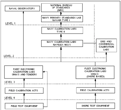
Figure 1-1.—Calibration laboratory structure.
METCAL provides assurance that your test equipment is in top-notch shape. Remember, your measurements are only as accurate as your test equipment; be fully aware of the limitations of your test equipment and never use equipment that isn’t properly calibrated when performing measurements or adjustments.
Q-1. What assures the accuracy of your electronic test equipment?
Operation and use of common test equipment was covered in NEETS Module 16, Introduction to Test Equipment, NAVEDTRA B72-16-00-95. It is recommended that you review this module before continuing.
VOLTAGE MEASUREMENTS
Most Navy technical manuals provide voltage charts that list correct voltages at all primary test points in a piece of equipment. Voltage measurements, when compared with these charts, provide a valuable aid in locating troubles quickly and easily. However, if the sensitivity of the test equipment differs from that of the test equipment used in preparing the chart, the voltage measurements may not reflect true circuit conditions. You must keep in mind that a voltmeter with low sensitivity used on a low range may disturb circuits under test or provide a false indication. Most technical manuals will tell you what type and model of test equipment was used to prepare the voltage charts. As a rule of thumb, the input impedance of the voltmeter should exceed the impedance of the circuit by a ratio of at least 10 to 1. Technicians have spent uncounted hours of wasted time because they have selected improper test
equipment.
Q-2. The input impedance of your test equipment should exceed the impedance of the circuit under test by what ratio?
DC VOLTAGE MEASUREMENTS
Direct current voltage may be steady, pulsating, or have ac superimposed on it. The average value of a dc waveform depends on the symmetry of the wave and other aspects of the wave shape. It can vary from 63.6% of peak value for a rectified full sine wave to 50% of peak value for a triangular wave. For a superimposed sine wave, the average value can be zero. Regardless of whether the dc is steady, pulsating, or the ac is superimposed on the dc, a rectifier form of measuring device will indicate its average value.
Voltages are usually measured by placing the measuring device in parallel with the component or circuit (load) to be measured. The measuring device should have an infinite internal resistance (input impedance) so that it will absorb no energy from the circuit under test and, therefore, measure the true voltage. The accuracy of the voltage measurement depends on the total resistance of the measuring device compared to the load being measured. When the input impedance of the measuring device is 10 times greater than the load being measured, the error usually can be tolerated. If this error cannot be tolerated, a high input impedance measuring device, such as a vacuum tube voltmeter (vtvm), should be used.
Alternatively, using two voltmeters in series increases the voltage range and, because of the increase in total voltmeter resistance, provides a more accurate measurement of voltage across the load. If the voltage to be measured is sufficiently high, more than two similar voltmeters can be connected in series across the load to provide greater accuracy; the total voltage measurement is the sum of the individual meter
indications.
Q-3. What are the advantages of using two voltmeters in series?
Multimeter Method
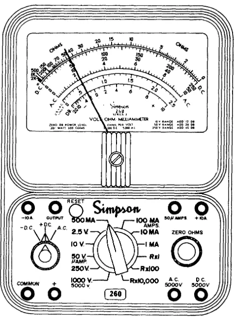
Figure 1-2.—Simpson 260 multimeter.
Two obvious advantages of the Simpson 260 are its portability and ease of operation. Among its disadvantages are its low input impedance and the inherent low accuracy associated with D’Arsonval meter movements, which are used in the meter. When performing measurements with any analog multimeter, remember that the most accurate readings are taken with the pointer midscale. You should also be aware of inaccuracies introduced as a result of parallax. PARALLAX is defined as the apparent displacement of the position of an object because of the difference between two points of view. In the case of meters, this means the position of a meter’s pointer will appear to be at different positions on the scale depending on the angle from which the meter is viewed. Some of the Simpson 260 and 270 series multimeters have effectively eliminated the problem of parallax by incorporating a mirror on the scale that accurately reflects the position of the pointer of the meter movement.
Q-4. At what point on a meter movement are the most accurate readings taken?
Oscilloscope Method
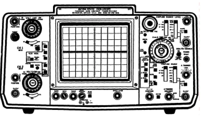
A dc voltage measurement can be made with an oscilloscope, as shown in figure 1-3, that has a direct-coupled deflection amplifier or terminals for connection directly to the deflection plates of the cathode-ray tube. Measuring a dc voltage with an oscilloscope is convenient only under certain
Figure 1-3.—Dual-trace oscilloscope.
Oscilloscopes have a high input impedance and normally will not load down the circuit under test. However, oscilloscopes are primarily designed for waveform observation and are typically less accurate than other pieces of test equipment used to measure dc voltages. A distinct advantage of the oscilloscope is its ability to monitor the level of ac ripple voltage riding the dc voltage. This feature makes the
oscilloscope an indispensable aid in troubleshooting dc power supplies with excessive ripple caused by component failure.
Digital Multimeter Method
[image:19.612.138.481.68.271.2]Most analog voltmeters (that use D’Arsonval meter movements) in common use today are accurate to approximately ±2% of full-scale reading. Most digital multimeters, as shown in figure 1-4, have a high input impedance and are not likely to disturb the circuit being tested. The digital multimeter in most cases provides an accuracy of at least ±0.1%.
Figure 1-4.—Digital multimeter.
by computers, printers, tape and card punches, and magnetic-tape equipment. Digital multimeters are typically compact and lightweight; many come with rechargeable batteries, making them ideal for portable field use. The disadvantages are that they are not rugged and will not tolerate abuse and that some models do not produce sufficient bias voltage to test a diode or transistor junction. The John Fluke Model 77 A/N digital multimeter is presently being purchased by the Navy and will eventually phase out the older and less accurate analog meters.
Differential Voltmeter Method
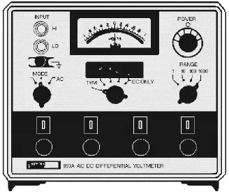
[image:20.612.145.473.301.579.2]Using the differential voltmeter, as shown in figure 1-5, provides one of the most accurate methods of measuring dc voltage. Typical accuracies attained by this method are ±0.005%. These extremely high accuracies are achieved by the design of the voltmeter with precision internal reference voltages and precision resistors. As discussed earlier in NEETS, module 6, Introduction to Electronic Emission, Tubes, and Power Supplies, most differential voltmeters can be operated as transistor voltmeters (tvm) or as differential null voltmeters. The tvm mode is used to measure the approximate voltage and polarity of the unknown voltage being measured. The approximate voltage, as measured in the tvm mode, is then used to make the initial range and mode switch selections for nulling the input voltage.
Figure 1-5.—Ac-dc differential voltmeter.
The advantages of using a differential voltmeter for measuring dc voltages are the extreme accuracy and minimal circuit loading made possible by the high input impedance of the meter. However,
differential voltmeters are less portable, heavier, and require greater skill and time when performing measurements than other types of voltmeters. Additionally, they require long warm-up periods and are susceptible to variations in temperature and humidity.
AC VOLTAGE MEASUREMENTS
When ac voltage measurements are performed, the input impedance of the selected test equipment determines the amount of energy removed from the circuit under test. If an ac meter is placed across a high-impedance circuit, the meter may load the high-impedance circuit and disturb circuit conditions, possibly to the point of causing the circuit to cease functioning. A dc electronic voltmeter, used in conjunction with a rectifying probe, extracts only a small amount of energy from the circuit under test. Another advantage of an electronic voltmeter over the analog voltmeter is that voltages of low values can be accurately measured.
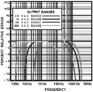
[image:21.612.149.467.380.693.2]If the circuit being measured is a relatively high-frequency circuit, the internal capacitance of an analog voltmeter rectifier could produce a disturbance by detuning the circuit. Figure 1-6 depicts the frequency response of a Simpson 260. Note the percent of error introduced at different frequencies. For high-frequency voltage measurements, an electronic voltmeter or an oscilloscope should be used. The sensitivity of the meter (or oscilloscope) determines the lowest voltage it can measure accurately, and the shunt capacitance of its input determines the upper frequency limits. It should be clear that the frequency response of a piece of test equipment is just as important as its range limitations. If you exceed the range limitations of a meter, it will either "peg" the meter or belch out the smell of smoke that many of us are intimately acquainted with. This, however, is not the case when you exceed the frequency limitations of your test equipment. Your test equipment will normally show a response, but that response will be grossly inaccurate. The lesson to be learned here is that you should be fully aware of the limitations of your test equipment and adhere to them.
Q-6. The frequency response of test equipment refers to what aspect of ac voltage measurements?
Multimeter Method
As previously stated, an analog multimeter’s usefulness is limited by its low input impedance and poor accuracy (typically ±2%). However, rugged construction and ease of operation make analog multimeters extremely useful whenever poor accuracy and low input impedance can be tolerated. When performing ac voltage measurements with a multimeter, be certain that the frequency of the signal being measured falls within the upper and lower frequency limitations of the meter.
Oscilloscope Method
A major advantage of using an oscilloscope for ac voltage measurements is that the waveform can be observed; consequently, errors in measuring complex peak voltages are minimized. An oscilloscope may be used as a high-impedance ac voltmeter. In standard oscilloscopes, the vertical amplifier input
impedance is generally greater than 1 megohm, making it possible to measure voltages in high-impedance circuits. If the signal is applied directly to the plates, rather than at the vertical amplifier input, the input impedance is increased considerably.
Voltage measurements are most easily made when the deflection of the trace extends across the major portion of the oscilloscope screen; whenever possible, the trace should cover at least 60% of the vertical viewing area of the screen. If the amplitude of the measured voltage is very low, the trace dimensions may be small. If a voltage to be measured is large and cannot be attenuated to a usable value by attenuation circuits within the oscilloscope, an external resistive or capacitive voltage divider can be used. Such voltage dividers are often furnished with oscilloscope test sets and are called HIGH
VOLTAGE PROBES. When the voltage of pulses or other complete waveforms is being measured, the high voltage probe selected must be so designed as not to distort the measured signal. Most probes have adjustable (compensating) capacitors that are used to adjust the symmetry of the displayed waveform. You adjust the probe by monitoring either the calibrator output of the oscilloscope or a known good signal and adjusting the probe for a symmetrical display. Oscilloscopes are calibrated to display peak-to-peak values. To determine the rms voltage of a sinusoidal signal, divide the number of graticule units from the positive to the negative peaks by two and multiply this value by 0.707. When using the oscilloscope for ac voltage measurements, ensure the upper frequency range of the oscilloscope is not exceeded; otherwise, inaccurate values will be displayed. Most commonly used oscilloscopes have a frequency response from dc up to 100 megahertz.
Q-7. Ideally, an oscilloscope presentation should cover what vertical portion of the screen?
Digital Multimeter Method
As previously mentioned, digital multimeters present a high input impedance to the circuit under test and are fairly accurate. Many earlier models had very limited frequency responses. Even today the upper frequency limitations of digital multimeters vary from 20 kilohertz to over 300 kilohertz, depending on the model. Their upper frequency limitations can, however, be significantly extended by using optional rf probes. When you perform ac voltage measurements with a digital multimeter, remember that they are true rms indicating devices.
Differential Voltmeter Method
CURRENT MEASUREMENTS
Unless an ammeter is already an integral part of the circuit under test, current measurements are rarely taken. In the case of a high-resistance circuit, it will contain such a small amount of current that it cannot be measured accurately with ordinary field test equipment. In lower resistance circuits, current measurements can be taken only if the ammeter is placed in series with the circuit under test. These measurements require that a circuit connection be unsoldered or otherwise opened to insert the meter in series with the circuit. An easier method you may use to obtain a current measurement is to take a voltage measurement across a known resistance and calculate the current with Ohm’s law. The accuracy of current measurements depends on the internal resistance of the meter as compared with the resistance of the external circuit. If the total circuit current is decreased by increasing the load, then the percentage of error will decrease. Therefore, greater accuracy is obtained if the meter resistance is considerably less than the load resistance. A method of obtaining greater accuracy of current measurement is to decrease the total internal meter resistance with respect to load resistance. This is accomplished by connecting two ammeters in parallel with each other and in series with the circuit in which the current is being measured. Additional ammeters may be connected in parallel in the same manner for increased accuracy. This method also increases the range of measurements that can be taken. The arithmetical sum of the
indications of all the parallel meters represents the total current flow in the circuit. You should note that this is not a common test method and that your test equipment may be damaged if connected incorrectly. MULTIMETER METHOD
As previously mentioned, current measurements are usually taken by breaking the current path of the circuit under test and electrically inserting a meter in series. This is normally accomplished by
disconnecting a wire from a terminal or unsoldering one end of a component and electrically inserting the meter in series using the meter leads. This method is both time consuming and usually requires the use of a soldering iron, which can damage components. Most analog multimeters cannot be used for measuring ac current and are only accurate to within ±2% on dc ranges.
Q-8. What are the advantages of connecting ammeters in parallel when performing current measurements?
DIGITAL MULTIMETER METHOD
Unlike the analog multimeter, the digital multimeter will measure ac current as well as dc current. Again, current measurements are taken by breaking the current path and inserting the meter in series. Regardless of whether you’re using an analog multimeter or digital multimeter, this procedure for measuring current is time consuming. However, there is a major advantage to be gained by using the digital multimeter — its high degree of accuracy. The Fluke 8000A digital multimeter, for example, is accurate to within ±0.3% when measuring dc current and ±1% when measuring ac current. These accuracies are representative of most medium-priced digital multimeters.
CURRENT TRACERS
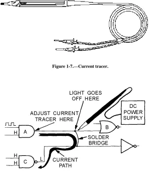
ideally suited for locating shorted or opened printed-circuit-board runs, wires, or components. In the absence of a suitable pulsing current to drive the current tracer, a logic pulser or pulse generator may be used as a signal source. The inherent disadvantage of a current tracer is that it requires an external power supply. They can, however, be connected to the power supply of the equipment under test if the voltage is correct.
Figure 1-7.—Current tracer.
Figure 1-8.—Current tracer application. CURRENT PROBES
Figure 1-9.—Current probe used with electronic ammeter. Q-9. What is the primary advantage of using a current probe?
OSCILLOSCOPE METHOD
Current can be measured with an oscilloscope by shunting the input terminals with a low-value resistor. The input terminals must then be connected in series with the circuit being tested. The value of the resistor must be small enough not to interfere with the operation of the circuit under test. At the same time, it must be large enough that the voltage developed will cause adequate deflection of the oscilloscope trace. For example, if an oscilloscope with a vertical deflection sensitivity of 0.1volt rms per centimeter (cm) is used in conjunction with a 10-ohm shunt resistor to measure a 25-milliamp current, the vertical trace will be deflected 2.5 centimeters, as shown in the following example:
shunt resistor and measure the calibration signal voltage developed across it with an accurate voltmeter. The calibration signal current can then be calculated by means of Ohm’s law. Since the oscilloscope merely indicates the voltage developed across the shunt resistor, the measurements for alternating or direct current will be similar to voltage measurements using an oscilloscope.
RESISTANCE MEASUREMENTS
A high percentage of technical manuals contain point-to-point resistance charts that list correct resistance readings for major test points. These resistance charts are extremely useful when you
troubleshoot faulty equipment. Without them, equipment resistance measurements within a complicated circuit would not mean much. Many circuits contain other circuit elements, such as capacitors, coils, or other resistors in parallel with the resistances being measured. This, of course, is a possible source of measurement error that you eliminate when you disconnect or unsolder one side of the resistor or a group of resistors under test.
You should be thoroughly familiar with the calibration of your ohmmeter. Analog meters are typically more accurate and easier to read at midscale. With the exception of bridge circuits, a meter may provide only approximate resistance readings. However, these readings may be adequate when you also consider the wide tolerances of resistors themselves. An ohmmeter that you use in field testing should be portable, convenient, and simple to operate - factors that usually are more important than extreme accuracy.
When an ohmmeter is used, completely de-energize the circuit under test and remove any current-sensitive elements before the resistance measurement is performed. Low-resistance measurements that require precision readings should be taken with a bridge type of instrument.
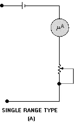
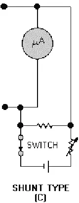
[image:26.612.246.376.473.688.2]An ohmmeter consists of a galvanometer, batteries, and resistors of known value that are connected in such a way that unknown resistors to be measured are compared with standard values. Figure 1-10 illustrates three basic ohmmeter circuits: (A) single range type, (B) series multirange type, and (C) shunt type.
Figure 1-10B.—Basic ohmmeter circuits.
Figure 1-10C.—Basic ohmmeter circuits. MULTIMETER METHOD
Ohmmeter applications include resistance measurements; continuity checks; and inductor, capacitor, and transformer checks. A transformer, for example, may be tested by checking whether there is an open or short, low-insulation resistance to ground, or improper continuity between transformer windings. A capacitor may be tested to determine whether it is open or shorted. Ensure that capacitors are properly discharged before you test them; otherwise, damage to the multimeter may occur. When an ohmmeter is placed in series with a capacitor, the changing current will cause a meter deflection that is proportional to the capacitance. The deflection obtained is compared with the deflection from a similar capacitor of known value. This deflection may be small or large, depending on the type and size of the capacitor and the voltage of the battery within the meter. An external series battery will increase the sensitivity of the instrument.
Q-10. How do you compensate for the resistance of the test leads of a meter?
DIGITAL MULTIMETER
The two major advantages of using a digital multimeter are its ease of operation and accuracy. Most digital multimeters can be ordered with an optional battery pack, which makes them just as portable as an analog multimeter. Another advantage is that their LED or LCD readouts are much easier to read than the scale on an analog multimeter. Digital multimeters also are ideally suited for measuring sensitive devices that might otherwise be damaged by the excessive current associated with analog multimeters —
maximum current flow through the component being tested is typically limited to less than 1 milliamp. When measuring small values of resistances, remember to consider the resistance of your test leads. Most digital multimeters cannot be zeroed in the way analog multimeters can. With digital multimeters, you have to short the leads, read the lead resistance displayed, and then subtract the reading from subsequent component measurements that you make.
Q-11. Why are digital multimeters well suited for testing sensitive devices?
RCL BRIDGES
The 250DE+1325 is a typical resistance, capacitance, inductance (rcl) bridge. Like the vtvm, the rcl bridge has several disadvantages. It requires ac power and a lengthy warm-up period, and its accuracy is limited to ±2%. The rcl bridge uses a tuning indicator electron tube, commonly referred to as the bridge's "eye," and an internal arrangement of resistors that form a Wheatstone bridge. As discussed in NEETS, module 16, the rcl bridge can be a time-consuming method of performing resistance measurements.
Difficulty may be experienced when you attempt to measure wire-wound resistors. To obtain a sharp balance on the indicator, you can shunt the resistor with a variable capacitor and adjust the capacitor for the clearest indication. The resistance measurement will not be affected by this reactance neutralization. MEGGERS
DIFFERENTIAL VOLTMETERS
It is a seldom-known fact that the Fluke 893 ac-dc differential voltmeter can be used for measuring extremely high resistances from 10 megohms to 106 megohms with a typical accuracy of ±5%. This measurement method, however, requires some basic calculations on your part. The obvious advantage of the differential voltmeter is its capability of measuring extremely high resistances. Consult the Fluke 893 technical manual for initial switch settings and a more detailed explanation of its operation.
CAPACITOR MEASUREMENTS
Capacitance is that property of a circuit that produces an electrostatic field when two conducting bodies separated by a dielectric material have a potential applied to them. Capacitors are made by compressing an insulating material (dielectric) between two conductors (plates). The farad is the basic measurement of capacitance. It is dependent upon the area of the plates, the distance between the plates, and the type of dielectric used. Electrically, the farad is a measure of 1 coulomb of potential charged by 1 volt. A coulomb (the amount of current flow maintained at 1 ampere that passes a given point of a circuit in 1 second) is a large charge. Most capacitors are measured in millionths of a farad (microfarad), expressed as ∝F, or in one-millionth of a microfarad (picofarad), expressed as pF.
Capacitors incur various losses as a result of such factors as resistance in the conductors (plates) or leads, current leakage, and dielectric absorption, all of which affect the power factor of the capacitor. Theoretically, the power factor of an ideal capacitor should be zero; however, the losses listed above cause the power factors of practical capacitors to range from near 0 to a possible 100%. The average power factor for good capacitors, excluding electrolytics, is 2% to 3%. Current leakage, which is an inverse function of frequency, is important only at the lower frequencies and becomes negligible at higher frequencies. Dielectric absorption (sometimes referred to as dielectric viscosity) results in losses that produce heat. The effect of this type of loss is the same as resistance in series with the capacitor.
You have probably learned the hard way that some capacitors can retain a charge long after the voltage has been removed. The electrical charge retained by capacitors in de-energized electronic circuits is, in many cases, sufficient to cause a lethal shock. Be sure you and those working with you consider this hazard before performing any type of maintenance on any electrical or electronic circuit and before making connections to a seemingly dead circuit. Use extreme caution prior to working on or near de-energized circuits that employ large capacitors. Be safe—discharge and ground all high-voltage
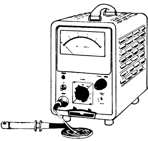
Figure 1-11.—Safety shorting probe.
When using the general-purpose safety shorting probe, always be sure first to connect the grounding clip to a good ground connection (if necessary, scrape the paint off the grounding metal to make a good contact — paint can be replaced, lives can't). Then, while holding the safety shorting probe by the handle behind the protective shield, touch the end of the metal rod to the points to be discharged. Touch each point several times to ensure that the circuit is completely discharged. Be extremely careful that you do not touch any of the metal parts of the safety shorting probe while touching the probe to the exposed "hot" terminal. Don't develop a nonchalant or routine attitude about these procedures. It pays to be safe; use the safety shorting probe with care.
Large capacitors, dormant in storage, can also develop a large static charge. This charge is caused by environmental conditions such as a close proximity to an rf field. An easy way to avoid this condition is to short the stored capacitor's terminals with a piece of wire before putting it in storage. Remember to remove the wire before installing the capacitor. If you receive a large capacitor that is not shorted, short the terminals together. Remember, CHARGED CAPACITORS CAN KILL.
Q-12. Charged capacitors can kill. True or false?
BRIDGE-TYPE MEASUREMENTS
Capacitor tests involving quality and value must be made in the course of everyday troubleshooting. You must make the important decision of whether to reject or continue to use a certain capacitor after it has been tested. Capacitance measurements are usually accomplished by either a bridge-type or a reactance-type capacitance meter. The bridge-type capacitance meter is much more accurate than the reactance-type meter. You may want to review rcl bridges in chapter 1 of NEETS, module 16, before reading further. Capacitance tolerances vary more widely than resistance tolerances and are dependent upon the type of capacitor, the capacitance value, and the voltage rating. The results of capacitance tests must be evaluated to determine whether a particular capacitor will fulfill the requirements of the circuit in which it is used.
The power factor of a capacitor is important because it is an indication of the various losses attributable to the dielectric, such as current leakage and dielectric absorption. Current leakage is of considerable importance, especially in electrolytic capacitors.
Figure 1-12 is a simplified schematic of a capacitance bridge. As you can see, a capacitance bridge is very similar in construction to a resistance bridge with the exception of the standard capacitor (CS) and the unknown capacitor (C X). Because current varies inversely with resistance and directly with
Figure 1-12.—Simplified capacitance bridge.
It is actually the capacitive reactance, rather than the capacitance, that is balanced in this circuit. In addition to its reactive properties, the capacitor under test always exhibits some loss. This loss may have the characteristics of either a shunt or series resistance, or it may be a combination of both. Regardless of its true nature, the loss can always be represented as a simple series resistance, which is shown in figure 1-12 as R X. This loss is balanced by the calibrated resistor R S. Rather than calibrate this control in terms of resistance, it is convenient to calibrate it in terms of the dissipation factor (the ratio of the energy dissipated to the energy stored in a capacitor). The RS control then provides the means for completing the capacitance balance, and its dial reading indicates a loss figure for the capacitor under test.
Q-13. Which is more accurate, the bridge- or reactance-type meter?
REACTANCE-TYPE MEASUREMENTS
The reactance type of capacitance measuring equipment makes use of the following principle: If an ac voltage (usually 6.3 volts) at a fixed frequency is applied across a capacitor and resistor in series, the voltage drop produced across the reactance of the capacitor by the resulting current flow is inversely proportional to the capacitance. The voltage drop is used to actuate a meter that is calibrated in
course is made up of both the reactance and the resistance. Therefore, the capacitance indicated by the analyzer will be lower than the actual value.
Figure 1-13 shows a simplified schematic diagram of the capacitance-measuring section of a typical reactance-type electronic volt-ohm-capacitance milliammeter. A 6.3-vac voltage is taken from the
filament source and applied across the resistive voltage divider network to determine the designated value of the capacitor. Because of a particular use or circuit application, some capacitors are permitted an even wider variation of capacitance value than is indicated by their rated tolerances.
Figure 1-13.—Reactance-type capacitance meter.
INDUCTANCE MEASUREMENT
A current flowing through a conductor produces a magnetic field around that conductor. If the conductor is formed into a coil, a stronger magnetic field is set up. The relationship between the strength of the field and the intensity of the current causing it is expressed by the inductance of the coil (or conductor). When the current producing the magnetic field ceases, the energy of the magnetic field is returned in part to the circuit source in the form of a reverse current. Inductance, then, is the ability of a coil to function as a storehouse of energy in magnetic form and is determined by the shape and
dimensions of the coil. Inductance is measured in henries, millihenries, or microhenries. Inductors can be described generally as circuit elements used to introduce inductive reactance into ac circuits.
high Q (discussed briefly at the end of this section) are generally required. These coils usually are single-layered with air or metallic cores. Since comparatively low values of inductance are required, this type of coil is very compact, and relatively high values of Q are obtained.
At frequencies in the lf and mf regions of the frequency spectrum, single-layered, universal, spiral, and other types of windings are used. When size is a factor, the more compact windings are preferred to the single-layered type of coil. At frequencies below 500 kilohertz, the single-layered type is too large for practical use; therefore, the more compact types are used exclusively.
The inherent resistance of the conductor with which an inductor is wound is the most important factor contributing to the losses of the inductor. Losses caused by this resistance increase with frequency. This results in a concentration of current near the outer surface of the wire, called SKIN EFFECT. Skin effect is negligible at low frequencies, but can be an important factor at high frequencies. Other
contributing factors to inductor losses are (1) eddy currents set up in the core and surrounding objects (if they are conductors); (2) the dielectric properties of the form used for the coil and surrounding objects; and (3) hysteresis in the core and surrounding objects, if they are magnetic metals. Losses occur as a result of the dielectric properties of the coil form because of the distributed capacitance of the inductor (for example, between turns and between the terminals and leads). To some extent the core and
surrounding objects serve as a dielectric of the distributed capacitance, and the resulting dielectric losses contribute to the overall losses of the inductor.
As we discussed earlier, an inductor has the ability to act as a storehouse of magnetic energy. However, because of the various loss factors described above, all of the energy stored in the magnetic field is not returned to the source when the applied voltage decreases to zero. The losses of an inductor may be represented by an equivalent series resistance. The value that it would dissipate would be an amount of energy equal to the total amount dissipated by the inductor. The losses of an inductor may be expressed in terms of the ratio of its inductive reactance to its equivalent series resistance. This ratio is referred to as the Q of the inductor and is stated in equation form as shown below:
Q-14. What type of core produces the greatest inductance?
HAY BRIDGE
Figure 1-14.—Bridge circuits.
The Hay bridge (view B of fig. 1-14) measures inductance by comparing it with a capacitance; it differs from the Maxwell bridge (view C) in that the resistance associated with the capacitance is a series instead of a shunt resistance. The inductance balance depends upon the losses (Q) of the inductor. The Hay bridge is used for inductors with low losses low D dial reading or high Q) at 1 kilohertz. This circuit is in effect when the FUNCTION switch is turned to the L(D) position. For a D dial reading up to 0.05, the error is 0.25%. Above this point the error increases rapidly and affects the basic accuracy of the test equipment. This limitation is expressed on the front panel of the test equipment as follows: IF D>0.05 ON L(D)—REBALANCE ON L(Q) . In other words, if the dissipation of an inductor, as read on the D dial when using the Hay bridge (FUNCTION switch set to L(D) position), exceeds 0.05, then you should change to the Maxwell bridge (FUNCTION switch set to L(Q) position), which is discussed in the following paragraph. The loss factor of the inductor under test is then balanced in terms of the Q of the inductor.
MAXWELL BRIDGE
The Maxwell bridge, shown in view C of figure 1-14, measures inductance by comparing it with a capacitance and (effectively) two resistances.] This bridge circuit is employed for measuring inductances having losses greater than 0.05 (expressed by the D dial reading). For such inductors it is necessary to introduce, in place of the series control (D dial), a new loss control (Q dial), which shunts the standard capacitor. This control, which becomes effective when the FUNCTION switch is turned to the L(Q) position, is conveniently calibrated in values of Q, the storage factor of the inductor under measurement. The balance for inductance is the same for either bridge circuit. This permits the use of the same markings on the RANGE switch for both the L(D) and L(Q) positions of the FUNCTION switch.
REACTANCE MEASURING EQUIPMENT
The reactance type of inductance measuring equipment makes use of the following principle: If an ac voltage of fixed frequency is applied across an inductor (and a resistor in series), the voltage drop
produced across the reactance of the inductor by the resulting current flow is directly proportional to the value of the inductance. An inductance measurement using the reactance method is identical to
capacitance measurements using the same method, except that current flow is directly proportional to the value of inductance, rather than inversely proportional as in the case of capacitance. It follows then that if a reactance-type capacitance measuring equipment is provided with a chart that converts the capacitance readings to equivalent inductance values and a proper range multiplying factor, the same test setup can be used to measure both capacitance and inductance. In practice, test equipment using the reactance method for capacitance measurements usually provides an inductance conversion chart. Because the current flowing through the inductance under test is directly proportional to the value of inductance, the reciprocals of the capacitance range multipliers must be used; for example, a multiplier of 0.1 becomes
and a multiplier of 100 becomes
Q-16. Is the current flow through an inductor directly proportional or inversely proportional to its inductance value?
MEASUREMENT OF INDUCTANCE USING THE VTVM
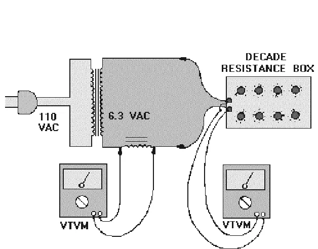
[image:36.612.141.455.385.631.2]If you do not have a 250DE+1325 at your disposal, the inductance of a coil can be determined by using a vtvm and a decade resistance box, as shown in figure 1-15. In the following example the inductance of an unknown coil in the secondary winding of a 6.3-volt filament transformer will be determined with a vtvm and decade resistance box. The unknown coil must be connected in series with the decade resistance box. The voltage across the decade box and across the coil must be monitored as the decade box is adjusted. When equal voltages are reached, read the resistance of the decade box. Since the voltage across the inductor equals the voltage across the decade box, the XL of the coil must be equal to the resistance read on the decade box. For example, assume that the resistance reading on the decade box is 4 kilohms and the frequency is 60 hertz. This must mean that the XL of the coil is also equal to 4,000 ohms. The inductance formula L = XL IFDQEHXVHGWRILQGWKHLQGXFWDQFHRIWKHFRLOLQKHQULHV
SUMMARY
This chapter has presented information on basic measurements. The information that follows summarizes the important points of this chapter.
The five basic measurements are VOLTAGE, CURRENT, RESISTANCE, CAPACITANCE, and INDUCTANCE. The accuracy of all measurements depends upon YOUR SKILL as a technician and the accuracy of your TEST EQUIPMENT.
Accuracy of different types of test equipment varies greatly and depends on design characteristics, tolerances of individual components, and YOUR KNOWLEDGE of test equipment applications.
The METCAL program ensures that your calibrated test equipment meets established specifications. Most equipment technical manuals contain VOLTAGE CHARTS which list correct voltages that should be obtained at various test points.
It is important to remember that the INPUT IMPEDANCE of your test equipment must be high enough to prevent circuit loading.
When you are performing ac voltage measurements, an additional consideration that greatly affects the accuracy of your measurements is the FREQUENCY LIMITATIONS of your test equipment.
When testing current-sensitive devices, you must be certain that the current produced by your test equipment does not exceed the current limitations of the device being tested.
Capacitance and inductance measurements are seldom required in the course of troubleshooting. These measurements are usually performed with various types of BRIDGES or with a reactance type of measuring device. The bridge -measuring techniques are more commonly used and are more accurate than reactance types of measurements.
REFERENCES
8000A Digital Multimeter, NAVSEA 0969-LP-279-9010, Naval Sea Systems Command, Washington, D.C., undated.
EIMB, Test Methods and Practices Handbook, NAVSEA 0967-LP-000-0130, Naval Sea Systems Command, Washington, D.C., 1980.
EIBM, General, NAVSEA 0967-000-0100, Naval Sea Systems Command, Washington, D.C., 1983.
Instruction Manual, Model 893A/AR AC-DC Differential Voltmeter, NAVSEA 0969-LP-279-7010, Naval Sea Systems Command, Washington, D.C., 1969.
Operation and Maintenance Instruction, Current Tracer 547A, NAVAIR 16-45-3103, Naval Air Systems Command, Washington, D.C., 1979.
Operation and Maintenance Instructions, Volt-Ohm-Milliammeter, 260 Series 6P, NAVSEA 0969-LP-286-1010, Naval Sea Systems Command, Washington, D.C., 1974.
ANSWERS TO QUESTIONS Q1. THROUGH Q16. A-1. Its calibration.
A-2. 10 to 1
A-3. Increased input impedance, greater accuracy, and increased voltage range.
A-4. Midscale.
A-5. Accuracy and high input impedance.
A-6. The range of frequencies that can accurately be measured.
A-7. At least 60% of the vertical trace.
A-8. Decreased internal meter resistance, greater accuracy, and greater current range.
A-9. Current probes enable you to perform current measurements without disconnecting wires. Current probes are clamped around the insulated wire.
A-10. By zeroing the meter with the test leads shorted.
A-11. The current flow through the component is limited to 1 milliamp.
A-12. True.
A-13. Bridge type.
A-14. Magnetic-metal core.
A-15. A capacitor.
CHAPTER 2
COMPONENT TESTING
LEARNING OBJECTIVES Upon completion of this chapter, you will be able to do the following: 1. Explain the importance of testing individual electronic components. 2. Identify the various methods of testing electron tubes.
3. Identify the various methods of testing semiconductors. 4. Identify the various methods of testing integrated circuits.
5. Identify the various types of testing batteries and their characteristics. 6. Identify the various methods of testing rf attenuators and resistive loads. 7. Identify the various methods of testing fiber-optic devices.
INTRODUCTION TO COMPONENT TESTING
It is imperative that you be able to troubleshoot an equipment failure to the component level. In the majority of cases, Navy technicians are expected to troubleshoot and identify faulty components. This chapter, "Component Testing," will acquaint you with alternative methods of testing various components and their parameters. A quick glance at the Navy’s mission and concept of operation explains why we, in most cases, must be able to troubleshoot to the faulty component level. A ship must be a self-sustaining unit when deployed. Storage space is a primary consideration on most ships and a limiting factor for storage of bulky items or electronic modules as ready spares. Therefore, it is practical to store only individual components common to a great number of equipment types. This of course, limits the larger replacement modules available to you during troubleshooting.
Q-1. Why are most ships limited in their ability to stock replacement modules for repair of electronic equipment?
TESTING ELECTRON TUBES
Because the operating capabilities and design features of a tube are demonstrated by its electrical characteristics, a tube is tested by measuring those characteristics and comparing them with representative values established for that type of tube. Tubes that read abnormally high or low with respect to the
standard are suspect. Practical considerations, which take into account the limitations of the tube test in predicting actual tube performance in a particular circuit, make it unnecessary to use complex and costly test equipment with laboratory accuracy. For most applications, testing of a single tube characteristic is good enough to determine tube performance. Some of the more important factors affecting the life expectancy of an electron tube are listed below:
• The circuit function of the tube
• Deterioration of the cathode coating
• A decrease in emission of impregnated emitters in aging filament-type tubes
• Defective seals that permit air to leak into the envelope and oxidize the emitting surface
• Internal short circuits and open circuits caused by vibration or excessive voltage
If the average receiving tube is not overdriven or operated continuously at maximum rating, it can have a life of at least 2,000 hours before the filament opens. Because of the expansion and contraction of tube elements during the process of heating and cooling, electrodes may lean or sag, which causes
excessive noise or microphonics to develop. Other electron-tube defects are cathode-to-heater leakage and nonuniform electron emission of the cathode. These common tube defects contribute to about 50% of all electronic equipment failures. For this reason you should immediately eliminate any tube known to be faulty. However, avoid blind or random replacement of good tubes with fresh spares. The most common cause of tube failure is open filaments. Evidence of a tube defect is often obvious when the filament is open in glass-envelope tubes. You will also notice the brighter-than-normal cherry-red glow of the plate when the plate current is excessive. Also, when the tube becomes gassy or when arcing occurs between electrodes, you will probably have visual indication. Metal-encased tubes can be felt for warmth to determine if the heater is operating. You can tap a tube while it is operating in a circuit to reveal an aural indication of loose elements within the tube or microphonics, which are produced by loose elements.
Most tubes are extremely fragile and subject to damage during shipment. When you replace a tube, never make the assumption that the new tube is good because it’s new. You should always test tubes before installing them.
Q-2. What is the most common cause of electron tube failure?
SUBSTITUTION METHODS
Substituting with a tube known to be in good condition is a simple method of testing a questionable tube. However, in high-frequency circuits tube substitution should be carried out in a logical sequence. Replace tubes one at a time so that you can observe the effect of differences in interelectrode capacitance in the substituted tubes on tuned circuits. The tube substitution test method cannot be used to advantage in locating more than one faulty tube in a single circuit for two reasons: (1) If both an rf amplifier tube and IF amplifier tube are defective in a receiver, replacing either one will not correct the trouble; and (2) if all the tubes are replaced, there is no way for you to know what tubes were defective. Under these
NOTE ON SYMBOLS USED IN THE FOLLOWING SECTIONS: IEEE and ANSI standards (see inside front cover) are used to define various terms, such as anode (plate) current, anode voltage, and anode resistance. This book uses Ea for anode voltage, Ia for anode current, and ra for anode resistance. These are the same as E, Ip, and rp that you will see elsewhere. This module uses the terms anode and plate interchangeably.
ELECTRON TUBE TESTERS
A representative field type of electron tube tester designed to test all common low-power tubes is shown in figure 2-1. The tube test conditions are as close as possible to actual tube operating conditions and are programmed on a prepunched card. The card switch (S101, fig. 2-1) automatically programs the tube test conditions when it is actuated by a card. A card compartment on the front panel of the tester provides storage for the most frequently used cards. The cover of the tester (not shown) contains the operating instructions, the brackets for storing the technical manual, the power cord, the calibration cell for checking the meter and short tests, the calibration cards, the blank cards, and a steel hand punch.
Figure 2-1.—Electron tube tester. Front Panel
The meter (M301) contains four scales. The upper scale is graduated from 0 to 100 for direct numerical readings. The three lower scales, numbered 1, 2, and 3, are read for LEAKAGE, QUALITY, and GAS, respectively. Each numbered scale includes green and red areas marked GOOD and
REPLACE. Inside a shield directly in front of the meter are five neon lamps (DS301 through DS305), which indicate shorts between tube elements.
The number 2 pushbutton (MP6) is used for transconductance, emission, and other quality tests (described later). The number 3 pushbutton (MP7) is used to test for the presence of gas in the tube envelope. The number 4 pushbutton (MP8) is used for tests on dual tubes. A neon lamp (DS203) lights when pushbutton number 4 is to be used. Eleven tube test sockets are located on the panel, plus tube pin straighteners for the 7- and 9-pin miniature tubes.
The power ON-OFF spring-return toggle switch (S105) turns the tester on by energizing a line relay. The pilot light (DS107) lights when this relay closes. Above the power ON-OFF switch are five fuses. Fuses F101, F201, and F202 protect circuits in the tester not protected by other means and have neon lamps to indicate when they have blown. Fuses F102 and F103 protect both sides of the power line. Auxiliary Compartment
A group of auxiliary controls covered by a hinged panel is used for special tests and for calibration of the tester. Two of these controls, labeled SIGNAL CAL (R152 and R155, fig. 2-2), are used with special test cards for adjusting the regulation and amplitude of the signal voltage. A pushbutton labeled CATH ACT (S302D) is used for making cathode activity tests. When this button is pressed, DS106 on the front panel (fig. 2-1) lights, and the filament voltage of the tube under test is reduced by 10%. Results of the test are read as a change in reading on the numerical meter scale.
Pushbutton S302E and potentiometers R401 and R405 (fig. 2-2) are used for balancing the transconductance (Gm) bridge circuit under actual tube operating current. Pressing S302E removes the grid signal and allows a zero balance to be made with one potentiometer or the other, depending upon whether the tube under test is passing high or low plate current. Lamp DS108 on the front panel lights when S302E is pressed. Pushbutton S302C is used for checking grid-to-cathode shorts at a sensitivity much higher than the normal tests. Results of this test are indicated by the short test lamps on the front panel.
Certain special tests require the use of a continuously adjustable auxiliary power supply. By pressing pushbutton S302B, you may use meter M301 to read the voltage of the auxiliary power supply on meter M301. This voltage may be adjusted by the use of the potentiometer R142. The rest of the potentiometer controls are calibration controls and are adjusted by the use of special calibration cards and a calibration test cell.
All circuits in the tester, except the filament supply, are electronically regulated to compensate for line voltage fluctuations. The filament supply voltage is adjusted by pressing pushbutton S302A and rotating the filament standardization adjustment switch S106 until meter M301 reads midscale. Program Cards
The circuits to be used in testing are selected by a prepunched card. These cards are made of tough vinyl plastic material. The tube numbers are printed in color on the tabs of the cards and also at the edge of the card for convenience in filing. A special card is provided to use as a marker when a card is removed for use. Blank cards are provided so that additional test cards may be punched for new tubes that are developed or to replace cards that have become unserviceable.
Operation
Before operating the tester for the first time, and periodically thereafter, you should calibrate it using the calibration test cards as described in the equipment technical manual.
NORMAL TESTS.—The tester is equipped with a three-conductor power cord, one wire of which is chassis ground. It should be plugged into a grounded 105- to 125-volt, 50- to 400-hertz outlet.
Before operating the tester, open the auxiliary compartment (fig. 2-2) and ensure that the FILAMENT STD ADJ and the Gm BAL knobs are in the NOM position. The GRID SIG and CATH ACT buttons (S302E and S302D) should be up and lamps DS108 and DS106 on the front panel should be out.
Turn on the tester and allow it to warm up for 5 to 10 minutes, then press the CARD REJECT KNOB (fig. 2-1) down until it locks. If a nontest card is installed in the card switch, remove it. This card is used to keep the switch pins in place during shipment and should be inserted before transporting the tester.
As soon as the card switch is actuated, the tube under test is automatically subjected to an
interelement short test and a heater-to-cathode leakage test. A blinking or steady glow of any of the short test lamps is an indication of an interelement short. If the short test lamps remain dark, no interelement shorts exist within the tube. If a short exists between two or more elements, the short test lamp or lamps connected between these elements remain dark, and the remaining lamps light. The abbreviations for the tube elements are located on the front panel just below the short test shield so that the neon lamps are between them. This enables the operator to tell which elements are shorted. Heater-to-cathode shorts are indicated as leakage currents on the #1 meter scale. If the meter reads above the green area, the tube should be replaced. A direct heater-to-cathode short causes the meter to read full scale.
To make the QUALITY test, push the number 2 button (fig. 2-1) and read the number 2 scale on meter M301 to determine if the tube is good. (This test may be one of various types, such as
transconductance, emission, plate current, or voltage drop, depending upon the type of tube under test.) To test the tube for GAS, press the number 3 button and read the number 3 meter scale. The number 2 button also goes down when number 3 is pressed. If a dual tube having two identical sections is being tested, the neon lamp (DS203) will light, indicating that both sections of the tube may be tested with one card. To do this, check the tube for shorts, leakage, quality, and gas as described previously; then hold down button number 4 and repeat these tests to test the second section of the tube. Dual tubes with
sections that are not identical require two cards for testing. A second card is also provided to make special tests on certain tubes.
AUXILIARY TEST.—As mentioned previously, two special tests (cathode activity and sensitive grid shorts) may be made by use of controls located in the auxiliary compartment (fig. 2-2). The cathode activity test (CATH ACT) is used to indicate the amount of useful life remaining in the tube. By reducing the filament voltage by 10 percent and allowing the cathode to cool off slightly, the ability of the cathode as an emitter of electrons can be estimated. This test is made in conjunction with the normal quality test.
To make the CATH ACT test, allow the tube under test to warm up, press button number 2 (f