z
RESEARCH ARTICLE
COMPARATIVE STUDY BETWEEN EXTENDED ADAPTIVE NEURO FUZZY INFERENCE SYSTEM
(EANFIS) AND CO-ACTIVE ADAPTIVE NEURO FUZZY INFERENCE SYSTEM (CANFIS) IN
CONTROLLING FULL CAR ACTIVE SUSPENSION SYSTEM
Jafar mouhsen Alkheir, Balsam Ahmad Eid and *Tarek faisal Barhoum
Department of Computers and Automatic Control Engineering, Faculty of Mechanical and Electrical
Engineering, Lattakia, Syria
ARTICLE INFO ABSTRACT
This Paper presents two adaptive vehicle suspension control methods, which significantly improve the performance of mechatronic suspension systems in full car model by absorbing shocks caused by bumpy roads and preventing vibrations from reaching the cockpit and providing stability and coherence required. The first control approach is an extension to the Adaptive Neuro-Fuzzy Inference System (ANFIS) called Extended adaptive Neuro fuzzy inference system (EANFIS). The second control approach is a special type of multi-inputs multi-outputs ANFIS model called Co-Active adaptive Neuro fuzzy inference system (CANFIS). MATLAB Simulink has used to build controllers and the full vehicle active suspension model with seven degrees of freedom. Three types of disturbances have been applied individually as excitations to test the robustness of the proposed controllers. In addition, a comparison between EANFIS controller, CANFIS controller and open loop model (passive suspension) has made with the three types of disturbances.
Copyright©2016, Jafar mouhsen Alkheir et al. This is an open access article distributed under the Creative Commons Attribution License, which permits
unrestricted use, distribution, and reproduction in any medium, provided the original work is properly cited.
INTRODUCTION
The entry of computer systems into many fields such car manufacturing developed new techniques, which led to prosperity of those fields. Concurrently with the technological developments in comfort, luxury and communications, cars manufacturing is witnessing another progress in the field of protection methods and stability control, these techniques has spread in most vehicles. The electronic control of suspension and steering system became one of the most important techniques in improving comfort, luxury and protection simultaneously. Active control of vehicle suspensions has been the subject of considerable investigation since the late 1960s; see, for example, (Hrovat 1990, Sunwoo and Cheok 1990) and the references therein. Ride safety and the handling capabilities of an automobile are mainly determined by its suspension system (Mitschke and Wallentowitz, 2004) that transmits the forces between the vehicle and the road (Guido P. A. Koch, 2011).
*Corresponding author: Tarek faisal Barhoum
Department of Computers and Automatic Control Engineering, Faculty of Mechanical and Electrical Engineering, Lattakia, Syria
The main aim of suspension system is to isolate a vehicle body from road irregularities in order to maximize passenger ride comfort and retain continuous road wheel contact in order to provide road holding (Lin and Kanellakopoulos, 1997). Demands for better ride comfort and controllability of road vehicles like passenger cars has motivated to develop new type of suspension systems like active and semi active suspension systems. These electronically controlled suspension systems can potentially improve the ride comfort as well as the road handling of the vehicle (Hrovat, 1990). An active suspension system has the capability to adjust itself continuously to changing road conditions. By changing its character to respond to varying road conditions, active suspension offers superior handling, road feel, responsiveness and safety (Rajamani and Hedrick, 1994). The suspension system must support the vehicle, provide directional control during handling maneuvers and provide effective isolation of passengers/payload from road disturbances. Good ride comfort requires a soft suspension, whereas insensitivity to applied loads requires stiff suspension. Suspension system defined as a link between vehicle's structure and the axles with wheels. The main function of this system is to maximize the friction between
ISSN: 0975-833X
Available online at http://www.journalcra.com
International Journal of Current Research
Vol. 8, Issue, 08, pp.36921-36930, August, 2016
INTERNATIONAL JOURNAL OF CURRENT RESEARCH
Article History:
Received 06thMay, 2016
Received in revised form 20thJune, 2016 Accepted 17thJuly, 2016
Published online 31stAugust, 2016
Key words:
EANFIS, CANFIS, ANFIS, Suspension system, Fuzzy logic, Neural networks,
Full car model, Fuzzy inference system.
Citation: Jafar mouhsen Alkheir, Balsam Ahmad Eid and Tarek faisal Barhoum. 2016.“Optimization of functional Spirulina cookies on their sensory attributes”,International Journal of Current Research, 8, (08), 36921-36930.
z
RESEARCH ARTICLE
COMPARATIVE STUDY BETWEEN EXTENDED ADAPTIVE NEURO FUZZY INFERENCE SYSTEM
(EANFIS) AND CO-ACTIVE ADAPTIVE NEURO FUZZY INFERENCE SYSTEM (CANFIS) IN
CONTROLLING FULL CAR ACTIVE SUSPENSION SYSTEM
Jafar mouhsen Alkheir, Balsam Ahmad Eid and *Tarek faisal Barhoum
Department of Computers and Automatic Control Engineering, Faculty of Mechanical and Electrical
Engineering, Lattakia, Syria
ARTICLE INFO ABSTRACT
This Paper presents two adaptive vehicle suspension control methods, which significantly improve the performance of mechatronic suspension systems in full car model by absorbing shocks caused by bumpy roads and preventing vibrations from reaching the cockpit and providing stability and coherence required. The first control approach is an extension to the Adaptive Neuro-Fuzzy Inference System (ANFIS) called Extended adaptive Neuro fuzzy inference system (EANFIS). The second control approach is a special type of multi-inputs multi-outputs ANFIS model called Co-Active adaptive Neuro fuzzy inference system (CANFIS). MATLAB Simulink has used to build controllers and the full vehicle active suspension model with seven degrees of freedom. Three types of disturbances have been applied individually as excitations to test the robustness of the proposed controllers. In addition, a comparison between EANFIS controller, CANFIS controller and open loop model (passive suspension) has made with the three types of disturbances.
Copyright©2016, Jafar mouhsen Alkheir et al. This is an open access article distributed under the Creative Commons Attribution License, which permits
unrestricted use, distribution, and reproduction in any medium, provided the original work is properly cited.
INTRODUCTION
The entry of computer systems into many fields such car manufacturing developed new techniques, which led to prosperity of those fields. Concurrently with the technological developments in comfort, luxury and communications, cars manufacturing is witnessing another progress in the field of protection methods and stability control, these techniques has spread in most vehicles. The electronic control of suspension and steering system became one of the most important techniques in improving comfort, luxury and protection simultaneously. Active control of vehicle suspensions has been the subject of considerable investigation since the late 1960s; see, for example, (Hrovat 1990, Sunwoo and Cheok 1990) and the references therein. Ride safety and the handling capabilities of an automobile are mainly determined by its suspension system (Mitschke and Wallentowitz, 2004) that transmits the forces between the vehicle and the road (Guido P. A. Koch, 2011).
*Corresponding author: Tarek faisal Barhoum
Department of Computers and Automatic Control Engineering, Faculty of Mechanical and Electrical Engineering, Lattakia, Syria
The main aim of suspension system is to isolate a vehicle body from road irregularities in order to maximize passenger ride comfort and retain continuous road wheel contact in order to provide road holding (Lin and Kanellakopoulos, 1997). Demands for better ride comfort and controllability of road vehicles like passenger cars has motivated to develop new type of suspension systems like active and semi active suspension systems. These electronically controlled suspension systems can potentially improve the ride comfort as well as the road handling of the vehicle (Hrovat, 1990). An active suspension system has the capability to adjust itself continuously to changing road conditions. By changing its character to respond to varying road conditions, active suspension offers superior handling, road feel, responsiveness and safety (Rajamani and Hedrick, 1994). The suspension system must support the vehicle, provide directional control during handling maneuvers and provide effective isolation of passengers/payload from road disturbances. Good ride comfort requires a soft suspension, whereas insensitivity to applied loads requires stiff suspension. Suspension system defined as a link between vehicle's structure and the axles with wheels. The main function of this system is to maximize the friction between
ISSN: 0975-833X
Available online at http://www.journalcra.com
International Journal of Current Research
Vol. 8, Issue, 08, pp.36921-36930, August, 2016
INTERNATIONAL JOURNAL OF CURRENT RESEARCH
Article History:
Received 06thMay, 2016
Received in revised form 20thJune, 2016 Accepted 17thJuly, 2016
Published online 31stAugust, 2016
Key words:
EANFIS, CANFIS, ANFIS, Suspension system, Fuzzy logic, Neural networks,
Full car model, Fuzzy inference system.
tires and the road surface in order to achieve the best firming on the road and maximum control in steering the vehicle, also providing a sense of comfort for passengers to reduce their sense of the presence of protuberances or bumps on the road. Major companies have made a qualitative leap in suspension systems of their latest versions of vehicles by replacing negative suspension systems (Passive) which is consisting of springs with shock absorbers by effective suspension systems (Active), which consists of sensors and actuators in addition to the Control unit and some hydraulic components. Actuators run by the controller, which depends on movement monitoring sensors of the steering wheel and the movement of the structure in order to keep the vehicle in the best possible stable condition. The presence of robust controller for modern suspension systems is very important in order to reduce the discomfort felt by passengers, which arises from road roughness, and to improve the road handling, which requires very fast and accurate controller to meet the key objectives as much as possible. Research presents two adaptive vehicle suspension control methods, depending on advanced Neuro-Fuzzy controllers. The first one is an extension to the Adaptive Neuro-Fuzzy Inference System (ANFIS) called (EANFIS). The advantage of EANFIS controller is that it can handle the nonlinearities faster than other control types. It believed that, this is the first time to use the EANFIS control method in controlling active suspension systems. The second controller is a special type of multi-inputs multi-outputs ANFIS model called Co-Active adaptive Neuro fuzzy inference system (CANFIS) which can send multi control signals to the hydraulic actuators at the same time. To investigate the problem of balancing riding comfort and road handling, the mathematical model of four-wheel active suspension systems should be introduced.
MATERIALS AND METHODS
The Concept of the Mathematical Model
The main function of a vehicle suspension system is to isolate the vehicle body from external excitation in order to improve
passenger comfort and road holding and to stabilize its movement. Riding comfort can be measured by evaluating the acceleration, the velocity and displacement of sprung mass.
Active Suspension System
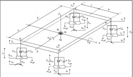
This section is devoted to the mathematical modeling of proposed model. Figure 1 shows the seven-degrees-of-freedom system that represents the full-vehicle active suspension model. It consists of an upper mass, representing the body mass (sprung mass), as well as a lower mass, representing the wheel mass (un-sprung mass), and its associated parts. The vertical motions of un-sprung mass are described by
, , ,
. And the vertical motions of sprung mass are described bỳ , ̀ , ̀ ̀
. the pitch motion is described by angle and roll motion is described by angle while the excitations due to road disturbance are q1,q2,q3,q4 . The data employed here for the full-vehicle system are listed in Table 1. Figure 1 illustrates the full vehicle active suspension system.With Applying Newton’s second law to the tires and body ,the equations of motion can be formulated as follows:
1. Vertical motion:
According to:
= − + ( ̀ − ) + ̀ − + +
+ (1)
= − + ( ̀ − ) + ̀ − + +
+ (2)
= − + ̀ − + ̀ − + + + (3)
= − + ̀ − + ̀ − + + + (4)
= ̀ − + ̀ − + ̀ − + ̀ − +
̀ − + ̀ − + ̀ − + ̀ − − − −
[image:2.595.85.520.531.781.2]− + − − − - (5)
Pitching motion
= − − ̀ + − ̀ + − ̀ +
− ̀ + [ ( − ̀ ) + − ̀ + ( − ̀ ) + − ̀ ] − ( + ) + ( + ) +( + ) −
+ (6)
Where d is 1/2 of the distance between the front wheels (or rear wheels). c is 1/2 of the distance between the front wheels(or rear wheels).
Rolling motion
= − − ̀ + − ̀ + − ̀ +
− ̀ + [ ( − ̀ ) + − ̀ + ( − ̀ ) + − ̀ ] − ( + ) + ( + ) +( +
) − + (7)
Where:
is the distance between the center of front wheel axle and the center of gravity of the vehicle.
b is the distance between the center of rear wheel axle and the center of gravity of the vehicle .
is a constant friction for 1 - front left half suspension. is a constant friction for 2 - rear left half suspension. is a constant friction for 3 - rear right half suspension. is a constant friction for 4 - front right half suspension. And :
̀ = − + (8)
̀ = + − (9)
̀ = + + (10)
̀ = + − (11)
The proposed active suspension system can be represented in the state space notation:
= + + (12)
= + + (13)
[image:3.595.308.562.251.362.2]The state matrices are represented in the appendix.
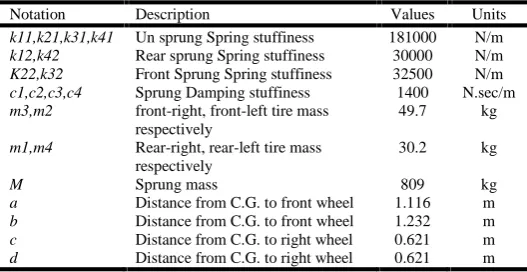
Table 1. The data employed for the full-vehicle system
Notation Description Values Units
k11,k21,k31,k41 Un sprung Spring stuffiness 181000 N/m k12,k42 Rear sprung Spring stuffiness 30000 N/m K22,k32 Front Sprung Spring stuffiness 32500 N/m c1,c2,c3,c4 Sprung Damping stuffiness 1400 N.sec/m m3,m2 front-right, front-left tire mass
respectively
49.7 kg
m1,m4 Rear-right, rear-left tire mass respectively
30.2 kg
M Sprung mass 809 kg
a Distance from C.G. to front wheel 1.116 m b Distance from C.G. to front wheel 1.232 m c Distance from C.G. to right wheel 0.621 m d Distance from C.G. to right wheel 0.621 m
Co-Active adaptive Neuro fuzzy inference system (CANFIS) (MIMO ANFIS)
The multi-inputs multi-outputs ANFIS model, or CANFIS for co-active ANFIS, was developed using the open source Toolbox CANFIS of Matlab software (version R2015b) based on. The hybrid Neuro fuzzy network uses the error back-propagation algorithm. A combination of two methods recursive least squares and back propagation gradient descent is implemented for training the neural network parameters to estimate the set of training data.
Description of ANFIS Operation
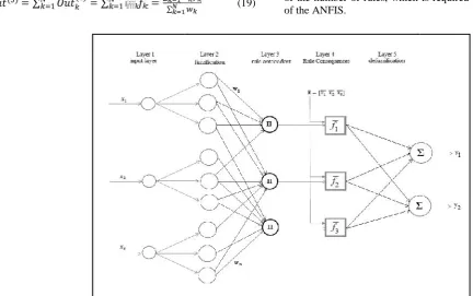
[image:3.595.30.294.602.738.2]The classic ANFIS (and CANFIS) consist of five layers. In the following lines, we describe briefly the operation of each layer.
Figure 2. Architecture of ANFIS
Layer No.1 (Inputs Layer)
In this layer, input fuzzification takes place. This means that each input is assigned a membership value to each fuzzy subset that comprises that input’suniverse of discourse.
Mathematically, this function can be expressed as:
( )=
(14)
Where ( )is the layer 1 node’s output, which corresponds to the j-th linguistic term of the i-th input variable. As example of membership generalized Gaussian function:
= (15)
Where i=1…..Number of input variables, j=1……Number of input terms.While the triplet of parameters (
, ,
) are referred to as premise parameters or non-linear parameters and they adjust the shape and the location of the membership function. Those parameters are adjusted during the training mode of operation by the error back-propagation algorithm. The output of each node in this layer represents the firing strength (or activation value) of the corresponding fuzzy rule.Layer No.2 (Fuzzy AND Operation)
Each node in this layer performs a fuzzy-AND operation. This result to each node’s output being the product of all of its
inputs (every input term node that is connected to that rule node):
∏ (16)
For all the term j connected to the k-th rule node, k=1… Number of rules. The output of each node in this layer represents the firing strength (or activation value) of the corresponding fuzzy rule.
Layer No.3 (Normalization)
The output of the k-th node is the firing strength of each rule divided by the total sum of the activation values of all the fuzzy rules. This results in the normalization of the activation value for each fuzzy rule. This operation is simply written as:
∑ (17)
Layer No. 4
Each node k in this layer is accompanied by a set of adjustable
parameters
,
, … .
,
and implements the linearfunction:
⋯ … (18)
The weight is the normalized activation value of the k-th rule, calculated in layer 3. Those parameters are called consequent parameters or linear parameters of the ANFIS.
Layer No.5 (Output Layer)
For ANFIS (MISO) this layer consists of one and only node that creates the network’s output as the algebraic sum of the node’s inputs:
∑ ∑ ∑∑ (19)
Description of CANFIS Operation
The operation of CANFIS network is the same as that of ANFIS up to Layer 3. The MIMO CANFIS network architecture changes from Layer 4 and forward.
Layer No.4 for CANFIS (MIMO)
In such a system, the output of the k-th fuzzy rule that influences the m-th network output is written as:
⋯ …
20
Where m=1……Numer of outputs, The parameters
, ,… , are the consequent parameters of the CANFIS system that represent the contribution of the k-th rule to the m-th output.
Layer No. 5 for CANFIS (MIMO)
The m-th output of the network is computed as the algebraic sum of the m-th node’s inputs:
∑
∑
(21)The structure of EANFIS
[image:4.595.46.479.523.794.2]The adaptive Neuro-fuzzy inference system (ANFIS) is a popular neuro-fuzzy system. It consists of a number of layers implementing the premises, and the consequences of a fuzzy system. It accepts various membership functions in the premises. However, it is known that ANFIS cannot be applied to inputs with high dimensions. The reason is that the ANFIS forms the pairwise combination of the inputs at the premises part. Thus, if there are many inputs, there will be an explosion of the number of rules, which is required in the premises part of the ANFIS.
Figure 3. Classic Architecture of Co-Active ANFIS
inputs (every input term node that is connected to that rule node):
∏ (16)
For all the term j connected to the k-th rule node, k=1… Number of rules. The output of each node in this layer represents the firing strength (or activation value) of the corresponding fuzzy rule.
Layer No.3 (Normalization)
The output of the k-th node is the firing strength of each rule divided by the total sum of the activation values of all the fuzzy rules. This results in the normalization of the activation value for each fuzzy rule. This operation is simply written as:
∑ (17)
Layer No. 4
Each node k in this layer is accompanied by a set of adjustable
parameters
,
, … .
,
and implements the linearfunction:
⋯ … (18)
The weight is the normalized activation value of the k-th rule, calculated in layer 3. Those parameters are called consequent parameters or linear parameters of the ANFIS.
Layer No.5 (Output Layer)
For ANFIS (MISO) this layer consists of one and only node that creates the network’s output as the algebraic sum of the node’s inputs:
∑ ∑ ∑∑ (19)
Description of CANFIS Operation
The operation of CANFIS network is the same as that of ANFIS up to Layer 3. The MIMO CANFIS network architecture changes from Layer 4 and forward.
Layer No.4 for CANFIS (MIMO)
In such a system, the output of the k-th fuzzy rule that influences the m-th network output is written as:
⋯ …
20
Where m=1……Numer of outputs, The parameters
, ,… , are the consequent parameters of the CANFIS system that represent the contribution of the k-th rule to the m-th output.
Layer No. 5 for CANFIS (MIMO)
The m-th output of the network is computed as the algebraic sum of the m-th node’s inputs:
∑
∑
(21)The structure of EANFIS
The adaptive Neuro-fuzzy inference system (ANFIS) is a popular neuro-fuzzy system. It consists of a number of layers implementing the premises, and the consequences of a fuzzy system. It accepts various membership functions in the premises. However, it is known that ANFIS cannot be applied to inputs with high dimensions. The reason is that the ANFIS forms the pairwise combination of the inputs at the premises part. Thus, if there are many inputs, there will be an explosion of the number of rules, which is required in the premises part of the ANFIS.
This has been a limiting factor in the application of ANFIS to practical systems with a high input dimensions. we recognize that the limiting factor in the ANFIS is due to its requirement to form the pairwise combination of the inputs, whether they are required or not. However, if there is a way in which we can determine what rules need to be formed, then we may avoid this explosion of the rules if the input dimension is high. EANFIS architecture may deploy various membership functions, e.g., triangular membership function, trapezoidal membership function, Gaussian membership function. Most of these membership functions require the determination of their parameters in a separate step. They would have difficulties adapting to an input, which may require a non-symmetric membership function. EANFIS architecture, we will use the self-organizing mountain clustering membership function. This membership function is in reality an approximate implementation of the common kernel density estimation technique common in non-parametric statistics. Hence, the membership function, not necessarily symmetric, can adapt to any input shape.
Thus, the EANFIS architecture consists of the following elements:
Membership function generation, Rule formulation,
Parameter learning related to the parameters associated with the layers, and
Output layer parameter learning.
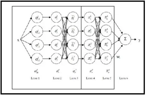
[image:5.595.47.284.511.664.2]In the EANFIS architecture, we need to expand the formulation of the ANFIS architecture dependent on the output. Let us assume that the output is discrete and there are T output classes. We will denote the desired output as di, where i = 1, 2, , , , , , , , I, the total number of training instances, and τ = 1, 2, . . . ,T, T being the number of output classes. The output of EANFIS IS where the output of the i-th input is
Figure 4. Architecture of EANFIS
EANFIS consists of six layer as following
Layer 1 (Input Layer)
In this layer the input vector , d = 1, 2, . . .,D. This input is fed into a membership module, which consists of C
membership function nodes. There are C membership functions for each input and for each output class τ. Let the output of the membership module be
( ); d = 1, 2. . . D, c = 1, 2. . . C andτ= 1, 2. . . T.
In effect, the outputs of the membership functions ( ) can be considered as a measure of the similarity between the input and the c-th membership function for a particular output class τ. If they are close, then the output of ( ) will be high. On the other hand, if the match between the c-th membership function and the input is low, then the corresponding output ( ) will be low.
Layer 2 (Rule Layer)
In this layer, the membership function outputs are multiplied together according to a specific scheme as follows: Assuming that for a particular output class τ each input dimension has C membership functions. Then, we start with d = 1, which has membership functions
ᵠ
,, ᵠ
,, … … … ᵠ
, .For d=2, there areᵠ
,, ᵠ
,, … … … ᵠ
, variables.We need to form pairwise combination of variables
ᵠ
, withthose of
ᵠ
, as follows:ᵠ
,, ᵠ
,, ᵠ
,, ᵠ
,, … … … , ᵠ
,ᵠ
, ,.…, ᵠ
,ᵠ
,, … … . , ᵠ
,ᵠ
, , a total of terms. Thenfor d = 3, we will need to form the terms
ᵠ
,, ᵠ
,, … , ᵠ
, With each of the products formed byconcatenating input dimensions 1 and 2 together. There will be
a total of terms, with the general form
ᵠ
,ᵠ
,, ᵠ
, .The method can be generalized to general value of d, until d = D. Thus, there will be in general rules for each value τ giving a total of T rules. We will denote each rule by
∅
with a general formᵠ
,ᵠ
,, … … … . . ᵠ
, . Eachmembership output product is equivalent to performing the fuzzy T-norm operation, representing the firing strength of this rule. Note that the total number of rules is R = T .
Layer 3 (Normalized Layer)
In this layer, it calculates the ratio of the firing strength to the total firing strength. In other words, this layer computes the normalized outputs of the rule layer.
∅ =
∑ ∅ ∅ (22)Note that layers 1 to 3 are the layers in the classic ANFIS except in this case we separate out each output class into a separate strand. Note also that ∅ ∈ [0,1] which denotes the normalized similarity of rule corresponding to the d-th input and the c-th membership function.
Layer 4 (Error Correction Layer)
This layer is used to “fine tune” the output of layer 3 by using a logistic function.
∅ ,
=
( ( )(∅ ) (23)∈
Where γ R is an adjustable parameter. Thus, the logistic function is one in which the slope γ can be adjusted. The output of this layer is
=
∅ ,
(24)In general, the fuzzy rule node outputs (in layer 3) in an ANFIS architecture may contain contradictions, overlaps or inconsistencies which may be attributed to the noise in the training data set or to the blurred cluster regions among different output clusters. The proposed error correction layer (layer 4) presents one way to solve these problems. Thus, this layer will become effective if the output of the Neuro-fuzzy system is ambiguous, e.g., if two rules are giving rise to similar outputs. In this case, it will be difficult to distinguish the effectiveness of the rules. However, using this layer, we will be able to distinguish the effectiveness of the rules. Obviously, this layer will not be required if all the rules give rise to well distinct outputs. The logic of this layer can be understood as follows:
If the degree of similarity ∅ is close to 1 and ∅ , is high then the output is high.
If the degree of similarity ∅ is close to 1 and ∅ , is small then the output is still high. It is because this can be thought of as a rarity situation when there are only very small samples of the case exist. If the degree of similarity ∅ is close to 0.5 and
∅ , is low then the output is low. It is because this fuzzy rule has a low ∅ , , which means it contributes many errors during the training process. The output from this rule is untrustworthy. The output strength πr is lower accordingly in this case.
If the degree of similarity ∅ is close to 0.5 and ∅ ,ã is high then the output is medium. If the ∅ , is high it does not apply any discount to the output .
This layer may be formally represented as follows:
And x2 is
, ᵠ
, and …and xd is, ᵠ
,ℎ =
∅
∅ ,
Rule r: If x1 is, ᵠ
,Layer 5 (Normalized Layer)
This layer performs the normalization of the outputs of Layer 4:
=
∑ ð (25)The output of this layer is normalized to lie between 0 and 1.
Layer 6 (Output Layer)
The output layer can accept two possible forms, viz. the zeroth order output and the TSK scheme respectively. For continuous outputs, we will assume that τ = 1. Thus, the continuous output case can be considered as a special case of the more general discrete output case. The adjustable parameters of this architecture are:
ã
, r = 1, 2, . . ., R andù
, in the case of zeroth order output function, and in addition,á
andá
, for r = 1, 2, . . ., R, and d = 1, 2, . . .,D in the case of TSK output mechanism. Furthermore, there are parameters associated with the membership functions as well. This depends on the membership function used. For example, if we use Gaussian membership function, then there will be two parameters associated with each membership function. On the other hand, if we use triangular membership function, then there will be three parameters associated with each membership function.RESULTS AND DISCUSSION
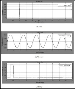
[image:6.595.306.559.418.717.2]The results obtained from the research works are presented in Tables and Figures. A simulation of the mathematical model and controllers are made in Matlab/Simulink R20015b environment. The numerical conditions consisted of step excitation, sinusoidal excitation, and bump excitation. It is assumed that the time delay for road exciting inputs q1,q2,q3 and q4 are 0,0.3,0.8 and 0.5 seconds respectively. Control policy was evaluated for its performance at controlling the sprung mass and un sprung mass according to a set of evaluation criteria.
Figure. 5. Road Profiles
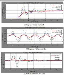
Figure.6. The responses of the system at point P1
[image:7.595.38.287.52.352.2]The graphics in Figure 7 show vehicle displacements with the three types of disturbance at point P2
Figure 7. The responses of the system at point P2
[image:7.595.37.290.415.705.2]The graphics in Figure 8 show vehicle displacements with the three types of disturbance at point P3
Figure 8. The responses of the system at point P3
The graphics in Figure 9 show vehicle displacements with the three types of disturbance at point P4.
Figure 9. The responses of the system at point P4
The graphics in Figure 10 show vehicle displacements with the three types of disturbance at point Pc (center of gravity point).
[image:7.595.309.563.419.707.2]Figure 10. The responses of the system at point Pc
Three types of control systems were compared and evaluated, namely, Eanfis, Canfis, and the Passive schemes. All the relevant parameters and conditions were kept the same for all the schemes to ensure a realistic and fair one-to-one comparison. It is generally considered an enhancement in system performance in riding comfort and road handling and vehicle stability if all the curves show a reduction in the amplitudes.
DISCUSSION
Figure (5) shows the three types of road profiles which will be applied as the disturbance input of the system , Figure (5) a shows step excitation, Figure (5)b shows sinusoidal excitation, and figure(5)c shows bump excitation. Figures 6,7,8,9,10 (a) demonstrate the distortion time output responses of the system at points P1,P2,P3,P4 and Pc respectively with the passive, CANFIS, and EANFIS schemes when step excitation is applied .Those figures depict that EANFIS controller rejected more than 80% of the distortion amplitude, which is better than the CANFIS controller and the passive system. Figures 6,7,8,9,10 (b) show the response of the system at points P1,P2,P3,P4 and Pc respectively under sinusoidal disturbance. As with the step input disturbance, the performance of the system clearly indicates that the EANFIS controller was much better than CANFIS controller and the Passive scheme at accommodating the introduced conditions. The magnitude of compensation was much greater than the step input. This further reaffirmed the robustness and effectiveness of the proposed scheme at controlling the vertical motion of the suspension system. With the system having sinusoidal disturbances, the EANFIS controller rejected more than 75% of the distortion amplitude, which is better than CANFIS controller, while the passive system only rejected a very small amount of the disturbance amplitude.
Figures 6,7,8,9,10 (c) show the response of the system at points P1,P2,P3,P4 and Pc respectively bump excitation is applied. The performance of the system indicates that the EANFIS controller rejected more than 70% of the distortion amplitude of the system which was again better than the CANFIS controller and the passive system. When all the results were compared, Figures depict that the open loop responses at each corner and at the gravity center of the vehicle are unacceptable which mean that passive suspension system is incapable of absorbing the vibrations. In addition, EANFIS controller could improve the ride comfort under the three types of road profile more than CANFIS controller .EANFIS reduced tire deflection the most. Moreover, this controller achieved much better road handling than CANFIS controller did.
Conclusion
This paper has presented simulation study using Matlab/Simulink using the extended adaptive Neuro fuzzy inference system (EANFIS) controller And Co-Active adaptive Neuro fuzzy inference system (CANFIS) controller to control full car model suspension system. The simulation results have shown that the responses of the vertical displacements at each suspension corner and the vertical displacement at the center of gravity have been reduced to acceptance value when the CANFIS controller is employed. In addition, EANFIS controller can suppress the worst-case step, sinusoidal, and bump function road disturbances effectively, and hence it could handle other, less severe real road situations better than CANFIS controller and passive system (open loop system). The results show that the use of the extended adaptive Neuro fuzzy inference system (EANFIS) control technique proved to be effective in controlling the vehicle and is more robust as compared to the Co-Active adaptive Neuro fuzzy inference system (CANFIS) control technique and the passive suspension system.
REFERENCES
Alleyne, A., Neuhaus, P. D. and J. K. Hedrick, 1993. Application of nonlinear control theory to electronically controlled suspensions, Vehicle System Dynamics, vol. 22, pp. 309–320.
Becker, G. 1993. Quadratic stability and performance of linear parameter dependent systems, Ph.D. dissertation, Dept. Mech. Eng., Univ. California Berkeley.
Becker, G. and Packard, A. 1994. Robust performance of linear parametrically Varying systems using parametrically dependent linear dynamic feedback, Syst. Contr. Lett., vol. 23, pp. 205–215.
Chalasani, R. M. 2006. Ride performance potential of active suspension systems Part 1, ASME Monograph, AMD vol. 80, DSC, vol 2.
Crosby, M. and D. C. Karnopp, 1973. The active damper a new concept for shock and vibration control, Shock Vibration. Bull, Part H, Washington D.C, pp. 35-42. Fard, H. and Samadi, F. 2015. Active Suspension System
Guido P. A. Koch, 2011. Adaptive Control of Mechatronic Vehicle Suspension Systems, Phd thesis.Technische Universitat Munchen.
Hardel, W. 1990. Applied Non-parametric Regression, Cambridge University Press, New York.
Hrova, D. 1990. Optimal active suspension structures for quarter-car vehicle models, Automatica, vol. 26, pp. 845– 860.
Jang, J.S. 1993. ANFIS: Adaptive-Network-Based Fuzzy Inference System, IEEE Trans. on Systems, Man and Cybernetics, vol. 23, pp. 665-685.
Jang, R. J.S., Sun C.T., Mizutani E. 1997. Neuro-Fuzzy and Soft Computing, A Computational Approach to Learning and Machine Intelligence, Prentice Hall, Upper Saddle River, NJ 07458.
Lin, C.J. and Lin, C.T. 1997. An ART-Based Fuzzy Adaptive Learning Control Network, IEEE Transactions on Fuzzy Systems, vol. 5, No. 4.
Lin, J.S and Kanellakopoulos, I. 1997. Nonlinear Design of ActiveSuspensions,”IEEE Control Systems Magazine, Vol. 17, No.3, pp.45-59.
Rajamani, R. and J.K. Hedrick, 1994. Performance of Active Automotive Suspensions with Hydraulic Actuators: Theory and Experiment, Proceedings of the American control conference.
Srivastav, P., Qureshi, M. 2014. Co-Active Neuro-Fuzzy Inference System for Governing Control and Excitation Control of Power System Stability, International Journal of Innovative Research in Science, Engineering and Technology, Vol. 3, Issue 6, PP.13410-13418.
Sunwoo, M. and Cheok, K. C. 1990. “An application of explicit self-tuning controller to vehicle active suspension systems,” in Proc. IEEE Conf. Decision Contr. pp. 2251– 2255.
Tharwat O. S. Hanafy, Al-Osaimy, Mosleh M. Al-Harthi 2014. Identification of Uncertain Nonlinear MIMO Spacecraft Systems Using Coactive Neuro Fuzzy Inference System (CANFIS), International Journal of Control, Automation and Systems, PP.25-37.
Yager, R.R. and Filev, D.P. 1994. Approximate Clustering Via the Mountain Method, IEEE Trans. on Systems, Man and Cybernetics, vol. 24, pp. 1279-1284.
Appendix:
The state matrices: