RESEARCH ARTICLE
DESIGN AND IMPLEMENTATION OF A CO-PROCESSOR FPGA-BASED-NUMERICAL RELAY
1Venkateshmurthy, B. S., *
,2Dr. Nataraj, K. R.,
3Dr. Rekha, K. R. and
4Dr. Mallikarjunaswamy, S.
1
Research Scholar, Jain University, Bengaluru, India
2Prof & HOD, Department of ECE, SJBIT, Bengaluru, India
3
Professor, Department of ECE, SJBIT, Bengaluru, India
4Associate Professor, Department of ECE, SJBIT, Bengaluru, India
ARTICLE INFO ABSTRACT
A co-processor numerical relay (CNR) is proposed in this paper which offers protection against abnormal conditions like over-voltage, under voltage, over current, over frequency and under frequency. The CNR also performs like a directional relay. Xilinx ISE 14.4 & synthesis has been performed on model-sim is used to investigates the performance of CNR. The prototype model is implemented using FPGA experimental kit. The proposed relay trips the circuit under any one of the abnormal conditional mentioned above. The proposed relay has numerous advantage including compact size and Co-processor functions for protection.
Copyright©2017, Venkateshmurthy et al. This is an open access article distributed under the Creative Commons Attribution License, which permits unrestricted use, distribution, and reproduction in any medium, provided the original work is properly cited.
INTRODUCTION
A protection scheme designed for any system should include various types of protective relays like over and under frequency relays, over and under voltage relays, over current relays. A relay will be so designed such that, under anomalous conditions the internal logic will enable the tripping sequence in the circuit (Network Protection & Automation Guide, 1995). Depending on the design considerations relays can be distinguished as electromechanical. Static and digital. Few designs of relay incorporate both static and digital techniques (Iagar et al., 2009). By utilising numerical relays, the crucial protective requirements like reliability, speed, sensitivity and selectivity can be achieved. Hence, there is tremendous scope for numerical relays in recent times and will soon replace the static relays. A Field programming Gate Array is used to obtain data, Perform necessary operations on the data acquired and to generate necessary real-time output data. Xilinx ISE 14.4 & synthesis has been performed on model-sim was used to model the FPGA based over & under voltage relay.10 GX FPGA Development Kit was used to build the model adopting inverse definite minimum time characterizes. Fuzzy logic controller was used to form a detailed report of DSP based over current relay using the IEEE standard inverse time characters digital
*Corresponding author: Dr. Nataraj, K R.
Professor& HOD, Department of ECE, SJBIT, Bengaluru, India.
directional and non-directional over current relay model was carried out (Price, 2010; Khederzadeh, 2011). The detail of the MATLAB model of frequency relay was done. Testing of relay for different frequency values was done without paying attention to load shedding for frequency relays (Darwish and Fikri, 2012; Elmore, 2014). TMS320F2812 DSP Kit was used to implement Co-processor numerical relay (CNR). It provided protection to the distribution system against over voltage, under voltage and over-current faults. Over and under frequency faults were not considered. The relays were designed to compare values and trip the circuit breakers. The standards of IEEE inverse time characteristic were not considered. Anolog to digital hardware circuit was used to perform conversion task. In this work, a CNR model is proposed that can provide protection against over voltage, under voltage, over frequency and under frequency various conditions of generation and loads were considered to design the relay. Analysis of the performance of CNR was done using Xilinx ISE 14.4 & synthesis has been performed on model-sim. A standalone PV system was used as a supply for different loading conditions. The prototype was implemented using FPGA experimental kit. The functional generator was used as a generator in the prototype. During any abnormal conditional with respect to current, voltage and frequency, the CNR tripped the circuit breaker. The proposed Co-processor numerical Relay (CNR) offers a wide range of features. Most important feature is that it
ISSN: 0975-833X
International Journal of Current Research Vol. 9, Issue, 06, pp.52500-52508, June, 2017
INTERNATIONAL JOURNAL OF CURRENT RESEARCH
Article History: Received xxxxxxxxx, 2017 Received in revised form xxxxxxxx, 2017 Accepted xxxxxxxx, 2017 Published online xxxxxxx,2017
Citation: Venkateshmurthy, B. S., Dr. Nataraj, K. R., Dr. Rekha, K. R. and Dr. Mallikarjunaswamy, S. 2017.“Design and implementation of a co-processor FPGA-based-numerical relay”,International Journal of Current Research, 9, (06), 52500-52508.
Key words:
Haratala, Arsenic. Article History: Received 23rdMarch, 2017
Received in revised form 10thApril, 2017
Accepted 12thMay, 2017
Published online 30thJune, 2017
Key words:
Co-processor Numerical Relay, Frequency analysis unit (FAU), Directional Feature model, FPGA, TMS320F2812.
RESEARCH ARTICLE
DESIGN AND IMPLEMENTATION OF A CO-PROCESSOR FPGA-BASED-NUMERICAL RELAY
1Venkateshmurthy, B. S., *
,2Dr. Nataraj, K. R.,
3Dr. Rekha, K. R. and
4Dr. Mallikarjunaswamy, S.
1
Research Scholar, Jain University, Bengaluru, India
2Prof & HOD, Department of ECE, SJBIT, Bengaluru, India
3
Professor, Department of ECE, SJBIT, Bengaluru, India
4Associate Professor, Department of ECE, SJBIT, Bengaluru, India
ARTICLE INFO ABSTRACT
A co-processor numerical relay (CNR) is proposed in this paper which offers protection against abnormal conditions like over-voltage, under voltage, over current, over frequency and under frequency. The CNR also performs like a directional relay. Xilinx ISE 14.4 & synthesis has been performed on model-sim is used to investigates the performance of CNR. The prototype model is implemented using FPGA experimental kit. The proposed relay trips the circuit under any one of the abnormal conditional mentioned above. The proposed relay has numerous advantage including compact size and Co-processor functions for protection.
Copyright©2017, Venkateshmurthy et al. This is an open access article distributed under the Creative Commons Attribution License, which permits unrestricted use, distribution, and reproduction in any medium, provided the original work is properly cited.
INTRODUCTION
A protection scheme designed for any system should include various types of protective relays like over and under frequency relays, over and under voltage relays, over current relays. A relay will be so designed such that, under anomalous conditions the internal logic will enable the tripping sequence in the circuit (Network Protection & Automation Guide, 1995). Depending on the design considerations relays can be distinguished as electromechanical. Static and digital. Few designs of relay incorporate both static and digital techniques (Iagar et al., 2009). By utilising numerical relays, the crucial protective requirements like reliability, speed, sensitivity and selectivity can be achieved. Hence, there is tremendous scope for numerical relays in recent times and will soon replace the static relays. A Field programming Gate Array is used to obtain data, Perform necessary operations on the data acquired and to generate necessary real-time output data. Xilinx ISE 14.4 & synthesis has been performed on model-sim was used to model the FPGA based over & under voltage relay.10 GX FPGA Development Kit was used to build the model adopting inverse definite minimum time characterizes. Fuzzy logic controller was used to form a detailed report of DSP based over current relay using the IEEE standard inverse time characters digital
*Corresponding author: Dr. Nataraj, K R.
Professor& HOD, Department of ECE, SJBIT, Bengaluru, India.
directional and non-directional over current relay model was carried out (Price, 2010; Khederzadeh, 2011). The detail of the MATLAB model of frequency relay was done. Testing of relay for different frequency values was done without paying attention to load shedding for frequency relays (Darwish and Fikri, 2012; Elmore, 2014). TMS320F2812 DSP Kit was used to implement Co-processor numerical relay (CNR). It provided protection to the distribution system against over voltage, under voltage and over-current faults. Over and under frequency faults were not considered. The relays were designed to compare values and trip the circuit breakers. The standards of IEEE inverse time characteristic were not considered. Anolog to digital hardware circuit was used to perform conversion task. In this work, a CNR model is proposed that can provide protection against over voltage, under voltage, over frequency and under frequency various conditions of generation and loads were considered to design the relay. Analysis of the performance of CNR was done using Xilinx ISE 14.4 & synthesis has been performed on model-sim. A standalone PV system was used as a supply for different loading conditions. The prototype was implemented using FPGA experimental kit. The functional generator was used as a generator in the prototype. During any abnormal conditional with respect to current, voltage and frequency, the CNR tripped the circuit breaker. The proposed Co-processor numerical Relay (CNR) offers a wide range of features. Most important feature is that it
ISSN: 0975-833X
International Journal of Current Research Vol. 9, Issue, 06, pp.52500-52508, June, 2017
INTERNATIONAL JOURNAL OF CURRENT RESEARCH
Article History: Received xxxxxxxxx, 2017 Received in revised form xxxxxxxx, 2017 Accepted xxxxxxxx, 2017 Published online xxxxxxx,2017
Citation: Venkateshmurthy, B. S., Dr. Nataraj, K. R., Dr. Rekha, K. R. and Dr. Mallikarjunaswamy, S. 2017.“Design and implementation of a co-processor FPGA-based-numerical relay”,International Journal of Current Research, 9, (06), 52500-52508.
Key words:
Haratala, Arsenic. Article History: Received 23rdMarch, 2017
Received in revised form 10thApril, 2017
Accepted 12thMay, 2017
Published online 30thJune, 2017
Key words:
offers protection for various types of faults. It is also an intelligent relay since it can avoid malfunction (Bedekar et al., 2009). Since it is a numerical based relay, it can adjust to the requirements of the system and makes CNR more suitable to adaptive protection algorithms and smart grid application. The CNR is also very compact in size.
Fig.1. The proposed CNR operating logic flow chart
Co-processor Numerical Relay
The details of the action mechanism of the proposed CNR for different cases is presented in the following subsections.
Over Current Protection
If the current that flows into the relay increases compares to the set point value, the relay will operate either with or without intended time delay, thereby tripping the associated circuit breakers (Vishwakarma and Moravej, 2011). If the over current flows through the circuit then it causes severe damage to the faulty and healthy sections of the power system. IEEE standard very inverse time characteristic equation for over current relays have to be incorporated in the design of MNR for over current conditions. The equations relate the relay current to relay’s
setting time (Al-Hasawi and Gilany, 2015).
= =
Where
I-Relay current n- Constant k- Constant Ip-Pick up current
For pick up value Ip exceeding the relay current I, the relay operating time equals the relay elapsed since the occurrences of fault conditions until the tripping of the relay (Tan et al., 2002).
Over and under voltage relay
Inverse time-voltage characteristics has been incorporated in proposed CNR for over voltage protection (Lin, 2006). Overheating caused due to over voltage results in severe damage to the system equation (1) gives the inverse characteristic for over voltage.
l -1 l =TMS ---- (1)
Fig.2. Proposed Co-processor Numerical model
Fig.3. The proposed model for FPGA based over-voltage function
Fig.4. Proposed model for the frequency analysis in CNR
Protection against under voltage or voltage sag
Inverse characteristic for under-voltage is the principle adopted for the proposed CNR. Equation (1) defines the inverse characteristic for overvoltage (TMS320F2810, 2016). Under voltage relay has a similar operating principle as that of overvoltage relay but with reverse logic.
Over and under frequency protection
If the frequency of the system deviates from the nominal value, then the proposed CNR trips the circuit breaker. If the frequency deviates, then the frequency is brought close to nominal value by the relay by shedding few loads, thereby maintaining continuity of the supply (Shuang et al., 2016). For a 50Hz supply the load shedding will be 33% if the magnitude
of frequency deviation l Δ f l exceeds ½ Hz, 66% if the magnitude of frequency l Δ f l exceeds 1Hz and 100% if the
magnitude of frequency l Δ f l exceeds 3/2Hz.During transient
conditions, in order to avoid the working of relay, delay time
Δt is set before shedding of load. This delay time can be set to
any desired value.
Directional relay characteristics of proposed CNR
The directional feature of the proposed CNR acts as a switch which allows power flow in right direction but trips the circuit breaker if the power flow occurs in reverse direction. This feature is important if the stand alone system have to be expanded by including additional PV sources and/or loads (Muzi, 2017; C2000 MCU Teaching ROM, TMS320F2812 Digital Signal Processor Implementation Tutorial, Texas Instruments). The proposed CNR will determine the power flow direction basedon phase shift θ between the waveform of
voltage and current (Dahnoun, 2014). The range of this angle is -900< θ < 900for normal operating conditions. If θ lies in this
range, the hatched interval that exist between voltage and current is longer than exists between voltage and current is longer than non-hatched interval (TMS320x281x DSP Analog-to-Digital Converter (ADC) Reference Guide, Texas Instruments, 2015; Campos et al., 2008). If the power flow is reversed the non-hatched interval will be longer.
Fig.5. Analysis of frequency of a signal in RTL model
Fig.6. Proposed FPGA based over frequency relay
Fig.7. Switching Directional feature model
Co-processor of proposed CNR
The logical operations of proposed CNR is as shown in fig 1. The system voltage and load current are the input signals to the relay (Computer representation of overcurrent relay characteristics, 1989; Yao-Hung Chan et al., 2010). The system frequency value is extracted from voltage signal. These values aid the CNR to serve as a directional relay. Depending on certain abnormality in the system, the CNR takes appropriate action.
Modelling and simulation
Xilinx ISE 14.4 & synthesis has been performed on model-sim is used for modelling and simulation of the proposed CNR. A stand-alone PV system is considered as the supply. The model of a stand-alone PV system is shown in Fig.2. The model contains a PV system, CNR relay, circuit breaker and a three phase motor in parallel to static load. The modelling of each function for each phase is explained in the subsections to be followed. For over and under voltage conditions, the relay decision depends on output of each block which will determine the output of a logic AND gate. For over and under frequency conditions, the relay decision is dependent on values assigned for shedding load.
Fig.8. Schematic of the implementation setup of the CNR
Over current model
The model for over current implemented by using Xilinx and model-sim is used for simulation. A sensing element is used to sense and measured the relay element.
Low pass filter
The design of low pass filter is made such that it extracts 50HZ fundamental component of the relay component.
Current comparator
The integrator operates based on the decisions made by the current comparator. The decision is made by comparator checking whether the RMS value of fundamental sensed current I is greater than picked up value of current Ip.
Time integrator and Comparator
If the current I is more than IP for a particular duration, then the time integrator operates until the In t product becomes equal to the value of K, which will make the relay send a trip signal.
Reset Logic
This logic is necessary to reset the time integrator if there is a temporary increase of current I above pickup value.
Models of over voltage and under voltage
The components required for over voltage model are shown in Fig.3.
Comparator
The integrator operates based on the decision given by comparator which compares system voltage V and setting value Vs.
Time Integrator
This time integrator operates as long as the voltage V is more than Vs.
Integrator output comparator
This compares the values of the expression l -1 l t with TMS value.
Reset Logic
If the voltage is above the upper-limit value under temporary condition, then this component is used to reset the time integrator.
Over and under frequency models
The proposed CNR consists of a frequency Analysis unit and Under-Over frequency identification element (FIE). The models of these two parts are shown in fig.4 and explained in the following subsections.
Frequency analysis unit (FAU)
FMU will measure the difference in time (T) between any two
successive zero crossing points. The ‘hit crossing block’ of
MATLAB is used for this purpose. The reciprocal of this measured time gives the frequency value. Fig.5 shows the
simulation model of FMU unit. A ‘hit crossing block’ detects
the zero crossing of the signal. The input signal is transferred
to the ‘if’ block at its zero crossings which in turn generates
the unity slope ramp signal at its output. A variable a saves the time duration of the ramp signal generated at this instant. This value of variable A is copied to another variable B .The time of the successive zero crossing instant is measured and saved to A. If the value in B is subtracted from A, it gives the half the
time period which is stored in ‘sample & hold’ block, until the signal reaches the next crossing instant. The instantaneous system is assessed after necessary computations. This value of frequency is then sent to FDE for necessary computation.
Over frequency detector
Fig 6 shows the components of frequency detector model and the explanation of each component is given below:
i.Detection frequency range
The frequency range is covered using 3 cascaded switches. Each frequency range has one switch assigned to it. The load shedding taken place after ∆ .
ii.Integrator
The block integrates the time duration for which the frequency is higher than the rated value.
iii.Integrator comparator
This compares integrator output with a 5s period signal. If the output of the period exceeds 5s period, then the output of the switches 1, 2, 3 will pass through multiport switch.
i.Multiport switch
A variable termed ‘shed’ receives the percentage of shedding
from the switch.
ii.Variable shed
Under frequency detector
To detect the under frequency, the CNR is modelled with the same logic as that of the over frequency but in reverse logic.
Directional feature model
Modelling of the directional element involves conversion of voltage and current element into a 2 level square wave. It has
‘H’ value for positive values and ‘-1’ for negative values of
signals. Multiplication of the 2 level voltage and current
signals give an output of ‘1’ for hatched interval and ‘-1’for
[image:5.595.43.282.341.488.2]non-hatched interval. This is followed by the integration of the product. The value of the integration of the product increases for normal power flow and decreases for reverse power flow. Fig 7 shows the RTL model for the directional feature of CNR. It contains switches s1, s2 which converts the waves of the voltage and current into a square wave. The switch s3 assigns
‘1’for product if overlapping occurs and ‘-1’ if non -overlapping occurs. The integrator integrates the product. Based on the output of the integrator, the switch s4 decides whether to trip or not the circuit breaker.
[image:5.595.100.502.514.782.2]Experimental implementation
Fig. 9. The complete setup of the CNR system
Fig.8. Illustrates a schematic of the implementation setup of the CNR. The signal (current and voltage) are sensed by sensors and are rescaled by voltage divider circuit containing 10kΩ and 5kΩ resistors followed by a bridge rectifier which
converts AC to DC. The complete setup of the proposed CNR is shown in Fig.9.
RESULTS
Electrical load
The electrical load is a 10 HP, 400V motor with a power factor of 0.885. The current during starting is 4 times the rated current value. The motor accelerates in 0.2 s. the raring of a static load is 1KW, 0.9 pf.
CNR Settings
Over current condition: Overloading. However the value should lie within the thermal characteristics of the MNR relay which is determined by thermal capability curves of the protected load under overloading conditions. IEEE standard very inverse time characteristic equation for over current relays are employed to choose the values A & n. if the Ip 20A, A =19.1 and n=2 then K=7850. Hence the relay trips when A. IpN=K=7850. A low pass filter reduces the THD, in order to mitigate the harmonic distortion. The THD is minimized by modelling the transfer functions of the filter suing trial and error method. In case of over voltage (236V/ph) and under voltage conditions (203V/ph) the proposed relay having system voltage of 220V/ph is designed with± 7.5% allowance for voltage swell sag. If the integrator output exceeds the TMS
value (ie; ‘1’), then the relay trips. If over frequency or under
frequency conditions arises the MNR is set to shed some load according to the deviation in frequency (∆f). If ∆f<± 5, the
‘shed’ variable is set to 1 and all loads remain connected. If±
0.5 < ∆f < ± 1, then 33% of the load has to be shed and the
shed’ variable is set to 2/3. If ± 0.5 < ∆f < ± 1.5 then the 66% of the load is shed by assigning 1/3 value to the shed
variable. In case∆f > 1.5 , ℎ ℎ 0, and all the loads are disconnected.
SIMULATION RESULTS
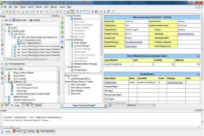
The proposed design of Co-processor Numerical Relay structure has been modeled by FPGA Kit using VHDL Code
and synthesis has been performed using the model-sim. The proposed Structures gate count is about 430000. Fig. 10. Shows the Execution Summary of proposed Co-processor Numerical model. The critical path of the structures is 3.64 ns with the 0.12 nm technology.
Fig.11. Shows the Internal structure of proposed Co-processor Numerical model
Fig.11. Internal structure of proposed Co-processor Numerical model
Fig.12. Shows the Schematic RTL structure of Proposed Co-processor Numerical model
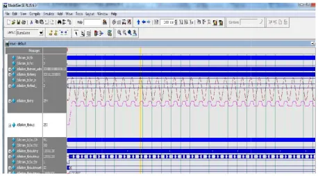
Fig.13. Shows the Waveform analysis of Proposed Co-processor Numerical model.
[image:7.595.66.529.370.738.2]Fig.13. Waveform analysis of Proposed Co-processor Numerical model
Table 1. Performance Comparisons between proposed co-processor Numerical Relay and existing system
S.No. Parameter Existing DSP based Numerical Relay Proposed FPGA based Numerical Relay
1 Operating Frequency 300MHz 491.6MHz
2 Trip Time Delay 13ps 8ps
3 Gate Count 120000 430000
4 Critical Path .18µm .12 nm
5 Phase variation 6ps 2ps
6 Voltage variation 4.5ps 1.75ps
7 Memory Interface Performance (Mb/s) 1800 2400
8 I/P Pins 956 1456
Fig .11. (a)
0 2 4 6 8 10 12 14
Trip Time Delay(ps) 13
8
Graphical performance comparison between
Proposed system and existing system
Existing DSP based Numerical Relay
Fig.13. Shows the Waveform analysis of Proposed Co-processor Numerical model.
Fig.13. Waveform analysis of Proposed Co-processor Numerical model
Table 1. Performance Comparisons between proposed co-processor Numerical Relay and existing system
S.No. Parameter Existing DSP based Numerical Relay Proposed FPGA based Numerical Relay
1 Operating Frequency 300MHz 491.6MHz
2 Trip Time Delay 13ps 8ps
3 Gate Count 120000 430000
4 Critical Path .18µm .12 nm
5 Phase variation 6ps 2ps
6 Voltage variation 4.5ps 1.75ps
7 Memory Interface Performance (Mb/s) 1800 2400
8 I/P Pins 956 1456
Fig .11. (a)
Trip Time Delay(ps) Phase variation(ps) Voltage variation(ps) 6
4.5 8
2 1.75
Graphical performance comparison between
Proposed system and existing system
Existing DSP based Numerical Relay Proposed FPGA based Numerical Relay
Fig.13. Shows the Waveform analysis of Proposed Co-processor Numerical model.
Fig.13. Waveform analysis of Proposed Co-processor Numerical model
Table 1. Performance Comparisons between proposed co-processor Numerical Relay and existing system
S.No. Parameter Existing DSP based Numerical Relay Proposed FPGA based Numerical Relay
1 Operating Frequency 300MHz 491.6MHz
2 Trip Time Delay 13ps 8ps
3 Gate Count 120000 430000
4 Critical Path .18µm .12 nm
5 Phase variation 6ps 2ps
6 Voltage variation 4.5ps 1.75ps
7 Memory Interface Performance (Mb/s) 1800 2400
8 I/P Pins 956 1456
Fig .11. (a)
Voltage variation(ps)
Conclusion
Testing of the proposed CNR relay model was done for various normal and abnormal working conditions. The performance characteristics of the relay for various conditions was recorded. Over-current operation of the relay was checked using three-phase faults, single-three-phase to ground fault and motor starting condition was seen as an abnormal one. Over and under voltage functions were tested using heavy and light loading conditions. The under and over frequency functions were checked by applying different frequency values. The performance of the relay was experimentally checked with the implemented prototype. The sensitivity and reliability of the proposed CNR was checked by implementing it on FPGA. The relay, in future can be modified to operate as a multi-relay device, i.e the same processor can have an increase in input sensors to sense voltage and current signals from different grid buses and an increases in output port to trip different relays according to CNR logic. This will lead to replacement of many relays by a single CNR relay.
REFERENCES
Al-Hasawi, W. and M. Gilany, 2015.“Proposed techniques for
identifying open and short circuit sections in distribution
networks,” WSEAS Trans. on Power Systems, 4(12), pp.
372- 381, December.
Bedekar, P. P., S. R. Bhide, and V. S. Kale, 2009.“Optimum
time coordination of overcurrent relays in distribution system using Big-M (Penalty) method,” WSEAS Trans. on
Power Systems, 4(11), pp. 341–350, November.
C2000 MCU Teaching ROM, TMS320F2812 Digital Signal Processor Implementation Tutorial, Texas Instruments.
Campos, D., E. Moreno, and D. Torres, 2008. “Test and
evaluation time inverse over-current protection algorithm
using SIMULINK,”Proc. Of the 7th WSEAS Int. Conf. on Signal Processing, Istanbul, Turkey, pp. 69–74.
Computer representation of over current relay characteristics, IEEE Power Engineering Review, vol. 9, pp. 50–51, July 1989.
Dahnoun, N. 2014. C6000 DSP Teaching ROM, Texas Instruments.
Darwish, H. A. and M. Fikri, 2012. “Practical considerations
for recursive DFT implementation in numerical relays,”
IEEE Trans. on Power Delivery, vol. 22, pp. 42–49, January.
Elmore, W. A. 2014. Protective Relaying Theory and Applications, ABB Power T&D Company Inc.
Iagar, A., G. N. Popa, C. M. Dinis, and G. Moraru, 2009.
“Study about numerical relaySEL-387 for overcurrent and
differential protections of 110/20 kV transformers,” in
Proc. of the 13th WSEAS Int. Conf. on Systems, Greece, pp. 265–270.
Khederzadeh, M. 2011. “Back-up protection of distance relay second zone by directional overcurrent relays with
combined curves,” in IEEE Power Engineering Society
General Meeting.
Lin, R. 2006.“Development of protective relaying equipment in substations,”Proc. of the 2006 IASME/WSEAS Int. Conf. on Energy & Environmental Systems, Chalkida, Greece, May 8-10, pp. 373–378.
Muzi, F. 2017. “A filtering procedure based on least squares
and Kalman algorithm for parameter estimate in distance
protection.”International Journal of Circuits, Systems and Signal Processing, 1(1), pp. 16–21.
Network Protection & Automation Guide, Areva T&D, 1995. Fig11. (b)
Fig .11 (a) & 11(b). Graphical performance comparison between proposed co-processor Numerical Relay and existing system
0 500 1000 1500 2000 2500
Gate Count ( x10) 120
430
Graphical performance comparison between
Proposed system and existing system
Existing DSP based Numerical Relay
Conclusion
Testing of the proposed CNR relay model was done for various normal and abnormal working conditions. The performance characteristics of the relay for various conditions was recorded. Over-current operation of the relay was checked using three-phase faults, single-three-phase to ground fault and motor starting condition was seen as an abnormal one. Over and under voltage functions were tested using heavy and light loading conditions. The under and over frequency functions were checked by applying different frequency values. The performance of the relay was experimentally checked with the implemented prototype. The sensitivity and reliability of the proposed CNR was checked by implementing it on FPGA. The relay, in future can be modified to operate as a multi-relay device, i.e the same processor can have an increase in input sensors to sense voltage and current signals from different grid buses and an increases in output port to trip different relays according to CNR logic. This will lead to replacement of many relays by a single CNR relay.
REFERENCES
Al-Hasawi, W. and M. Gilany, 2015.“Proposed techniques for
identifying open and short circuit sections in distribution
networks,” WSEAS Trans. on Power Systems, 4(12), pp.
372- 381, December.
Bedekar, P. P., S. R. Bhide, and V. S. Kale, 2009.“Optimum
time coordination of overcurrent relays in distribution system using Big-M (Penalty) method,” WSEAS Trans. on
Power Systems, 4(11), pp. 341–350, November.
C2000 MCU Teaching ROM, TMS320F2812 Digital Signal Processor Implementation Tutorial, Texas Instruments.
Campos, D., E. Moreno, and D. Torres, 2008. “Test and
evaluation time inverse over-current protection algorithm
using SIMULINK,”Proc. Of the 7th WSEAS Int. Conf. on Signal Processing, Istanbul, Turkey, pp. 69–74.
Computer representation of over current relay characteristics, IEEE Power Engineering Review, vol. 9, pp. 50–51, July 1989.
Dahnoun, N. 2014. C6000 DSP Teaching ROM, Texas Instruments.
Darwish, H. A. and M. Fikri, 2012. “Practical considerations
for recursive DFT implementation in numerical relays,”
IEEE Trans. on Power Delivery, vol. 22, pp. 42–49, January.
Elmore, W. A. 2014. Protective Relaying Theory and Applications, ABB Power T&D Company Inc.
Iagar, A., G. N. Popa, C. M. Dinis, and G. Moraru, 2009.
“Study about numerical relay SEL-387 for overcurrent and
differential protections of 110/20 kV transformers,” in
Proc. of the 13th WSEAS Int. Conf. on Systems, Greece, pp. 265–270.
Khederzadeh, M. 2011. “Back-up protection of distance relay second zone by directional overcurrent relays with
combined curves,” in IEEE Power Engineering Society
General Meeting.
Lin, R. 2006.“Development of protective relaying equipment in substations,”Proc. of the 2006 IASME/WSEAS Int. Conf. on Energy & Environmental Systems, Chalkida, Greece, May 8-10, pp. 373–378.
Muzi, F. 2017. “A filtering procedure based on least squares
and Kalman algorithm for parameter estimate in distance
protection.”International Journal of Circuits, Systems and Signal Processing, 1(1), pp. 16–21.
Network Protection & Automation Guide, Areva T&D, 1995. Fig11. (b)
Fig .11 (a) & 11(b). Graphical performance comparison between proposed co-processor Numerical Relay and existing system
Gate Count ( x10) Memory Interface Performance
(Mb/s)
I/P Pins Operating
Frequency (MHz) 1800 956 300 430 2400 1456 491.6
Graphical performance comparison between
Proposed system and existing system
Existing DSP based Numerical Relay Proposed FPGA based Numerical Relay
Conclusion
Testing of the proposed CNR relay model was done for various normal and abnormal working conditions. The performance characteristics of the relay for various conditions was recorded. Over-current operation of the relay was checked using three-phase faults, single-three-phase to ground fault and motor starting condition was seen as an abnormal one. Over and under voltage functions were tested using heavy and light loading conditions. The under and over frequency functions were checked by applying different frequency values. The performance of the relay was experimentally checked with the implemented prototype. The sensitivity and reliability of the proposed CNR was checked by implementing it on FPGA. The relay, in future can be modified to operate as a multi-relay device, i.e the same processor can have an increase in input sensors to sense voltage and current signals from different grid buses and an increases in output port to trip different relays according to CNR logic. This will lead to replacement of many relays by a single CNR relay.
REFERENCES
Al-Hasawi, W. and M. Gilany, 2015.“Proposed techniques for
identifying open and short circuit sections in distribution
networks,” WSEAS Trans. on Power Systems, 4(12), pp.
372- 381, December.
Bedekar, P. P., S. R. Bhide, and V. S. Kale, 2009.“Optimum
time coordination of overcurrent relays in distribution system using Big-M (Penalty) method,” WSEAS Trans. on
Power Systems, 4(11), pp. 341–350, November.
C2000 MCU Teaching ROM, TMS320F2812 Digital Signal Processor Implementation Tutorial, Texas Instruments.
Campos, D., E. Moreno, and D. Torres, 2008. “Test and
evaluation time inverse over-current protection algorithm
using SIMULINK,”Proc. Of the 7th WSEAS Int. Conf. on Signal Processing, Istanbul, Turkey, pp. 69–74.
Computer representation of over current relay characteristics, IEEE Power Engineering Review, vol. 9, pp. 50–51, July 1989.
Dahnoun, N. 2014. C6000 DSP Teaching ROM, Texas Instruments.
Darwish, H. A. and M. Fikri, 2012. “Practical considerations
for recursive DFT implementation in numerical relays,”
IEEE Trans. on Power Delivery, vol. 22, pp. 42–49, January.
Elmore, W. A. 2014. Protective Relaying Theory and Applications, ABB Power T&D Company Inc.
Iagar, A., G. N. Popa, C. M. Dinis, and G. Moraru, 2009.
“Study about numerical relay SEL-387 for overcurrent and
differential protections of 110/20 kV transformers,” in
Proc. of the 13th WSEAS Int. Conf. on Systems, Greece, pp. 265–270.
Khederzadeh, M. 2011. “Back-up protection of distance relay second zone by directional overcurrent relays with
combined curves,” in IEEE Power Engineering Society
General Meeting.
Lin, R. 2006.“Development of protective relaying equipment in substations,”Proc. of the 2006 IASME/WSEAS Int. Conf. on Energy & Environmental Systems, Chalkida, Greece, May 8-10, pp. 373–378.
Muzi, F. 2017. “A filtering procedure based on least squares
and Kalman algorithm for parameter estimate in distance
protection.”International Journal of Circuits, Systems and Signal Processing, 1(1), pp. 16–21.
Network Protection & Automation Guide, Areva T&D, 1995. Fig11. (b)
Fig .11 (a) & 11(b). Graphical performance comparison between proposed co-processor Numerical Relay and existing system
Operating Frequency (MHz)
491.6
Graphical performance comparison between
Proposed system and existing system
Price, E. 2010. “The next step in the evolution of protection and control implementation,” in Annual Conference for
Protective Relay Engineers, pp. 1–16.
Shuang, K., C. H. Chen, N. Xiao and D. Z. Yu, 2016.“A new
digital electronic governor based on 32 bits DSP for a gas
engine”, in9th Int. Conf. on Control, Automation, Robotics and Vision, 5–8 December, pp. 1–6.
Tan, J. C., P. G. McLaren, R. P. Jayasinghe, and P. L. Wilson, 2002.“Software model for inverse time overcurrent relays
incorporating IEC and IEEE standard curves,” inCanadian Conf. on Electrical and Computer Engineering, vol. 1, 12–
15 May, pp. 37–41.
TMS320F2810, TMS320F2811, TMS320F2812,
TMS320C2810, TMS320C2811, TMS320C2812 Digital Signal Processors Data Manual, Texas Instruments, 2016.
TMS320x281x DSP Analog-to-Digital Converter (ADC) Reference Guide, Texas Instruments, 2015.
Vishwakarma, D. N. and Z. Moravej, 2011. “ANN based directional overcurrent relay,” IEEE/PES Transmissionand
Distribution Conf. and Exposition,” vol. 1, 28 October–2 November, pp. 29–64.
Wang, F. and M. H. J. Bollen, 2013. Classification of component switching transients in the viewpoint of
protective relays,”Electric Power SystemsResearch, 64(3), pp. 197–207, March.
Yao-Hung Chan, Chi-Jui Wu, Wei-Neng Chang, and Ying-Pin Chang, 2010. “Voltage sag planning of industry power
system using hybrid differential evolution considering
CBEMA curve,”International Journal of Circuits, Systems and Signal Processing, 5(2), pp. 141–150.