ISSN Online: 2152-7393 ISSN Print: 2152-7385
DOI: 10.4236/am.2018.910075 Oct. 24, 2018 1104 Applied Mathematics
The Invulnerability of Directed Interdependent
Networks with Multiple Dependency Relations
Hanbing Gao
1,
Zhiming Ma
21Department of Service Command, Army Logistical University of PLA, Chongqing, China 2Army Logistics University of PLA, Chongqing, China
Abstract
The paper aims to study the invulnerability of directed interdependent net-works with multiple dependency relations: dependent and supportive. We establish three models and simulate in three network systems to deal with this question. To improve network invulnerability, we’d better avoid dependent relations transmission and add supportive relations symmetrically.
Keywords
Interdependent Networks, Dependency Relations, Invulnerability
1. Introduction
In recent years, there has been a significant advance in studying the proportion of complex networks. Most of the studies focus on the structure and function of single networks which do not contact with other networks [1]. But in fact, al-most all networks are connected with each other, such as power grid, transporta-tion and computer control systems. As a result, the failure in one network may cause the failure in connected networks, and vice versa. Along with this process, it may lead to cascading failure and cause serious damage. These networks are called interdependent networks [2].
Previous studies on interdependent networks are mostly restricted by this as-sumption: there are two networks, network A and network B. If node a in A which depends on node b in B, node b must depend on node a [3]. However, in real-world network systems, dependent relations transmission may exit. For example, node a1 in A depends on node b1 in B, node b1 doesn’t depend on a1 and it depends on another node a2 in A, node a2 doesn’t depend on b1 and it de-pends on another node b2 in B. a1 depends on b1, b1 depends on a2, a2 depends on How to cite this paper: Gao, H.B. and Ma,
Z.M. (2018) The Invulnerability of Directed Interdependent Networks with Multiple Dependency Relations. Applied Mathemat-ics, 9, 1104-1115.
https://doi.org/10.4236/am.2018.910075
Received: July 29, 2018 Accepted: October 21, 2018 Published: October 24, 2018
Copyright © 2018 by author and Scientific Research Publishing Inc. This work is licensed under the Creative Commons Attribution International License (CC BY 4.0).
http://creativecommons.org/licenses/by/4.0/
DOI: 10.4236/am.2018.910075 1105 Applied Mathematics b2; thus dependent relations are passed on. These networks are called directed interdependent networks.
There are two different types of dependency relations in current studies: 1) dependent—if node b depends on node a, the failure of node a must cause the failure of node b [4]. 2) supportive—if node a supports node b, the failure of node a may not cause the failure of node b; only if all nodes which support node b fail, there will be a failure of node b [5]. But it is a pity that most researchers only study one case, either dependent or supportive relation. In real-world net-work systems, these two types of dependency relations may exit simultaneously in one network system. For example, power grid and computer control system are connected with each other. A control center controls many generators dependently, so if there is a failure of the control center, all the generators will fail. But many generators support the control center; if a generator is failure, it may not cause the failure of the control center [6].
This paper focuses on the invulnerability of directed interdependent networks with multiple dependency relations. Three interdependent networks have been considered: interdependent scale-free (SF) networks, interdependent Er-dos-Renyi (ER) networks, and SF connected with ER network under random at-tack (ER network is common model for complex network research, in which each node was connected with a fix probability). Our work extends current study of interdependent network from undirected ones to directed ones, from single dependency relations to multiple dependency relations. The paper is organized as follows. In Section 2, three models will be established to study the invulner-ability of interdependent networks. In Section 3, the model will be simulated in interdependent SF networks, interdependent ER networks, and SF connected with ER network. In Section 4, the conclusion got from this paper will be shown.
2. Model
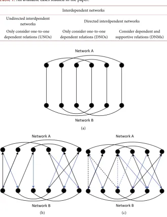
An interdependent network system has been generated, which includes network A and network B. For simplicity and without loss of generality, the number of nodes in network A and B are equal. To study the invulnerability of directed in-terdependent networks with multiple dependency relations, we build three mod-els: undirected interdependent networks connected by one-to-one dependent relations-UNOs; directed interdependent networks connected by one-to-one dependent relations-DNOs; directed interdependent networks connected by de-pendent and supportive relations-DNMs [7]. These three models are shown in Table 1 and Figures 1(a)-(c).
DOI: 10.4236/am.2018.910075 1106 Applied Mathematics Table 1. All available cases studied in the paper.
Interdependent networks Undirected interdpendent
networks Directed interdpendent networks Only consider one-to-one
dependent relations (UNOs) dependent relations (DNOs) Only consider one-to-one supportive relations (DNMs) Consider dependent and
(a)
(b) (c)
Figure 1. (a) Undirected interdependent networks connected by one-to-one dependent relations-UNOs; (b): Directed interdependent networks connected by one-to-one de-pendent relations-DNOs (lines of different colors represent dede-pendent relations of dif-ferent directions: black lines represent dependent relations from network B to network A; blue lines represent dependent relations from network A to network B); (c): Directed in-terdependent networks connected by dependent and supportive relations-DNMs (solid line and dashed line represent different types of dependency relations respectively: solid lines represent supportive relations; dashed lines represent dependent relations).
attack strategy for simplify, which means that one node in network A is removed randomly each time. The cascading failure process of the three models is a little different [8].
The cascading failure process of UNOs is shown below.
Step 1: Randomly remove a node in network A (remove the node together with all the edges connected to it, the same as the following ones).
Step 2: Remove the isolated node in network A and remove nodes in network Network A
Network B a
b
Network B
Network A Network A
DOI: 10.4236/am.2018.910075 1107 Applied Mathematics B corresponding to the failing nodes in network A.
Step 3: Remove the isolated node in network B and remove nodes in network A corresponding to the failing nodes in network B.
……
The cascading failure process stops unless the number of nodes either in net-work A or in netnet-work B is no longer dropping.
The cascading failure process of DNOs is below. Step 1: Randomly remove a node in network A.
Step 2: Remove the isolated node in network A and remove nodes in network B which depend on the failing nodes in network A.
Step 3: Remove the isolated node in network B and remove nodes in network A which depend on the failing nodes in network B.
……
The cascading failure process stops unless the number of nodes either in net-work A or in netnet-work B is no longer dropping.
The cascading failure process of DNMs is a little difficult, so that there are eight steps to describe this process.
Step 1: Randomly remove a node in the network A, and then turn to Step 2. Step 2: Remove the isolated node in the network A and judge the dependency relations from the failing node ai in the network A to bj in the network B. If the relation is supportive, turn to Step 3; if the relation is dependent, remove bj and turn to Step 4.
Step 3: Judge if there is any functional node in the network A that supports bj. Yes, turn to Step 4; no, remove bj and turn to Step 4.
Step 4: Judge if there is any node in the network B removed in the Step 2 and Step 3. Yes, turn to Step 5; no, turn to Step 8.
Step 5: Remove the isolated node in the network B and judge the dependency relations from the failing node bi in the network B to aj in the network A. If the relation is supportive, turn to Step 6; if the relation is dependent, remove aj and turn to Step 7.
Step 6: Judge if there is any functional node in the network B that supports aj. Yes, turn to Step 7; no, remove aj and turn to Step 8.
Step 7: Judge if there is any node in the network A removed in the Step 5 and Step 6. Yes, turn to Step 2; no, turn to Step 8.
Step 8: Judge if there is any functional node in the network A or network B. Yes, turn to Step 1; no, end.
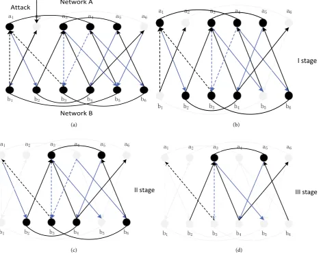
The form of graph has been adopted in order to express a better understand-ing of cascadunderstand-ing failure process of model 3 (regard it as a stage if one network causes changes in the other network).
DOI: 10.4236/am.2018.910075 1108 Applied Mathematics (a) (b)
[image:5.595.68.538.76.446.2](c) (d)
Figure 2. Description of the dynamic process of cascading failures of DNMs (transparent dots and lines represent the failure part).
of b1 causes the isolation of b5, so b5 fails (isolated failure). As shown in Figure 2(c), on the one hand, b1 fails, and a1 cannot depend on b1, so that a1 fails (de-pendent failure). On the other hand, b5 fails, and b5 cannot support a4 anymore and there is no node in network B supporting a4, so that a4 fails (supportive fail-ure). As shown in Figure 2(d), on the one hand, a1 fails, and a1 cannot support b2 anymore and there is no node in network A supporting b2, so that b2 fails (supportive failure). On the other hand, a4 fails, and b3 cannot depend on a4, so that b3 fails (dependent failure). The failure of b2 and b3 causes the isolation of b4 and b6, so b4 and b6 fail. So far, all the nodes in network B fail, and the attack is over. A different situation is that the number of nodes in network A or network B is no longer dropping and the cascading failure is over, therefore, more attacks should be made to test the invulnerability of interdependent networks.
3. Simulation
In this section, the invulnerability of UNOs, DNOs and DNMs will be tested. These tested models involve three interdependent networks: interdependent SF Network A
Network B a1
a1 aa22 aa33 aa44 aa55 aa66
b1
b1 bb22 bb33 bb44 bb55 bb66 Attack
a
a2
a2 aa33 aa44
b2
b2 bb33 bb44 bb55 bb66
a1
a1 aa55 aa66
b1
b1
I stage
b
a4 a4
b3
b3 bb44
b2
b2 bb55 bb66
a1
a1 aa22 aa33 aa55 aa66
b1 b1
II stage c
a4 a4 a1
a1 aa22 aa33 aa55 aa66
b1
b1 bb22 bb33 bb44 bb55 bb66
DOI: 10.4236/am.2018.910075 1109 Applied Mathematics networks, SF connected with ER network and interdependent ER networks. The number of SF network and ER network are 1000, the <k> of SF network and ER network are 4. The simulation environment is MATLAB R2015a [9].
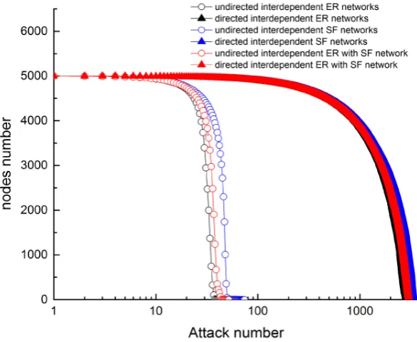
Firstly, compare UNOs with DNOs whose results are presented in Figure 3 (When attack number is zero, the initial node number of all networks is 5000, this doesn’t display on the diagram). No matter for which interdependent net-work (SF and SF, SF and ER, SF and SF), attack number of destroying directed interdependent networks is in the range [30, 100] and attack number of de-stroying undirected interdependent networks is more than 2000. The attack number of destroying undirected interdependent networks is much larger than that of destroying directed interdependent networks. Meanwhile, the final attack number can be taken as a sign of the invulnerability of network system and we will use this indicator to show network system invulnerability below.
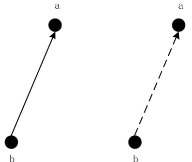
[image:6.595.227.520.430.670.2]Then, compare DNOs with DNMs. Firstly, there is a consideration of one-to-one dependency relations as shown in Figure 4. As the two cases shown in Figure 4, the dependency relation from node a to node b is supportive or de-pendent. Let’s review dependent failure and supportive failure: anyone of the nodes which it depends on fails; all of the nodes which support it fail. If node b fails, no matter the dependency relation from node a to node b is supportive or dependent, node a will fail. Therefore, it can be understood that, in terms of the one-to-one dependency relations, the effects of supportive or dependent tions are same. The second consideration is about two-to-one dependency rela-tions. The DNMs can be regarded as the improvement of DNOs, which means
DOI: 10.4236/am.2018.910075 1110 Applied Mathematics Figure 4. One-to-one dependency relations.
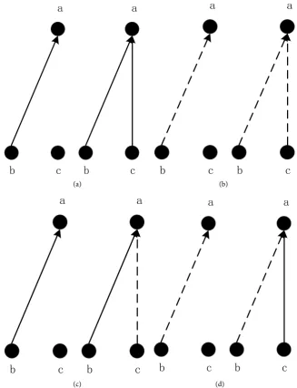
that DNMs is generated by adding dependent and supportive relations in the DNOs. The specific adding dependency relations rule is shown in Figure 5. Figure 5(a) can be understood like this: at the initial state, node b supports node a; now node c also supports node a, so that a supportive relation can be added from node c to node a. The realistic meaning of Figure 5(a) is to add reserve, which means that if node b fails, we can use node c to substitute. It is same as Figure 5(b): at the initial state, node a depends on node b; now node a depends on node c, so that a dependent relation can be added from node c to node a. The realistic meaning of Figure 5(b) is to add constraint, which means that not only node b but also node c is necessary to ensure node a to be functional. In addi-tion, there may be more than one supportive and (or) dependent relation(s) added to one node in the simulation process. Due to the limitation of paper, there is no need to repeat in Figure 5(c) and Figure 5(d). By expanding on the basis of two-to-one situation, more-to-one situation can be got.
In order to get DNMs, N1 number of dependent relations and N2 number of supportive relations are added to DNOs. We assume that the original network has a total of N edges, then two variables are defined: when p = N1/N, it means the increasing degree of supportive relations; when q = N2/N, it means the in-creasing degree of dependent relations. In addition, DNOs and DNMs are di-rected, and N11 can be used to indicate the increasing number of supportive rela-tions from network A to network B and use N12 to that from network B to net-work A. Besides, p1 and p2 are used to show the increasing degree, therefore, p = p1 + p2. Similarly, N21 and N22 are used to indicate the increasing number of de-pendent relations from network A to network B and then from network B to A. As well, the use of q1 and q2 can show the increasing degree, therefore, q = q1 + q2.
There are two factors mainly considered in this study of DNMs: the deviation to add dependency relations and the increasing number of dependency relations. The p* is used to indicate the deviation to add supportive relations and p* = p1 − p2. If the same number of supportive relations is added from network A to
a
a
b
b
a
a
DOI: 10.4236/am.2018.910075 1111 Applied Mathematics (a) (b)
[image:8.595.206.534.69.496.2](c) (d)
Figure 5. The adding dependency relations rules (solid line and dashed line represent different types of dependency relations: solid lines represent supportive relation and dashed lines represent dependent ones. (a) is about adding supportive relation on the ba-sis of itself. (b) is about adding dependent relation on the baba-sis of itself. (c) is about add-ing dependent relation on the basis of supportive relation; (d) is about addadd-ing supportive relation on the basis of dependent relation).
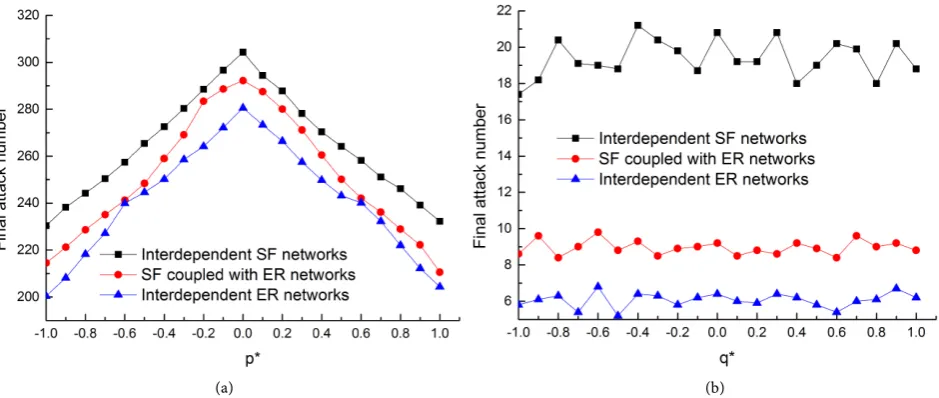
network B and then from network B to network A, which is to add supportive relations completely symmetrically, then p* = 0. The q* is used to indicate the deviation to add dependent relations and q* = q1 − q2. If the same number of dependent relations is added from network A to network B and then from net-work B to netnet-work A, which is to add dependent relations completely symmetri-cally, then q* = 0. In Figure 6(a), we keep p = 1, q = 0, and let p*changed within a certain range to study the impacts on the invulnerability of network systems by adding supportive relations with different deviations. As shown in Figure 6(a), in terms of the interdependent SF networks, the network invulnerability
a
a
b
b
c
c
a
a
b
b
c
c
a
a
a
a
b
b
c
c
a
a
b
b
c
c
b
b
a
a
b
b
c
c
a
a
b
b
c
c
c
c
a
a
b
b
c
c
a
a
b
b
c
c
DOI: 10.4236/am.2018.910075 1112 Applied Mathematics (a) (b)
Figure 6. The invulnerability of directed interdependent networks by adding dependency relations with different deviations. (a) is about adding supportive relations. (b) is about adding dependent relations. Results are from simulations averaged about 100 reali-zations.
becomes the lowest one in the situation of adding supportive relations com-pletely asymmetrically and the final attack number to destroy network system is about 200. With the tendency of adding supportive relations symmetrically, the network invulnerability increases gradually, and the network invulnerability be-comes the highest one in the situation of adding supportive relations completely symmetrically with the final attack number being about 305. The tendency is the same as SF connected with ER networks and interdependent ER networks, therefore, it can be concluded that to the supportive relations, adding supportive relations symmetrically is useful to improve the invulnerability of network sys-tems. Moreover, in terms of SF connected with ER networks, the final attack number to add supportive relations completely asymmetrically is about 215 and what to add supportive relations completely symmetrically is about 290. These two data for the interdependent ER networks are about 200 and 280 respectively. As a result, the conclusion is that, in terms of random attack, interdependent SF networks are more robust than interdependent ER networks, whose result meets well with [10].
DOI: 10.4236/am.2018.910075 1113 Applied Mathematics Finally, by adding different number of supportive and dependent relations, the invulnerability of directed interdependent networks has been studied in this paper. This question involves four variables: p1 p2 q1 q2. The question belongs to NP-hard question [11]. Limited by article length, only this situation can be un-der study, in which dependency relations can be completely added symmetri-cally. Keep p1 = p2 and q1 = q2, and then let p and q changed within a certain range, with the result shown in Figure 7. In terms of the interdependent ER networks, the result from Figure 7(a) can be understood. With the decrease of p, the invulnerability of network systems declines and with the decrease of q, the invulnerability of network systems raises [12]. When p = 1 and q = 0, the invul-nerability of network systems reaches its maximum with final attack number being about 305. When p = 0 and q = 1, the invulnerability of network systems reaches its minimum with final attack number being about 5. Meanwhile, the impacts on the invulnerability of network systems by increasing p or decreasing
q are nearly equal. These results also meet well with Figure 7(b) and Figure
7(c). Therefore, it can be concluded that adding supportive relations is useful to improve the invulnerability of network systems and adding dependent relations can decline the invulnerability of network systems. The effect of raising the in-vulnerability of network systems by adding supportive relations almost offsets the effects on declining the invulnerability of network systems by adding the same number of dependent relations.
4. Conclusion
DOI: 10.4236/am.2018.910075 1114 Applied Mathematics (a)
[image:11.595.61.541.70.424.2](b) (c)
Figure 7. The invulnerability of directed interdependent networks by adding different number of supportive and dependent rela-tions. (a) is about interdependent SF networks. (b) is about SF connected with ER networks. (c) is about interdependent ER net-work. There is a big distance between final attack number of directed interdependent networks with different number of increas-ing supportive and dependent relations. As a result, the logarithmic forms are used to indicate final attack number. Results are from simulations averaged about 100 realizations.
DOI: 10.4236/am.2018.910075 1115 Applied Mathematics
Conflicts of Interest
The author declares no conflicts of interest regarding the publication of this pa-per.
References
[1] Gao, J.X., Li, D.Q. and Havlin, S. (2014) From a Single Network to a Network of Networks. National Science Review, 1, 346-356.
[2] Shin, D.H., Qian, D. and Zhang, J. (2014) Cascading Effects in Interdependent Networks. IEEE Network, 28, 82-87.https://doi.org/10.1109/MNET.2014.6863136
[3] Chen, L., Peng, J. and Zhang, B. (2017) Uncertain Goal Programming Models for Bicriteria Solid Transportation Problem. Applied Soft Computing, 51, 49-59.
https://doi.org/10.1016/j.asoc.2016.11.027
[4] Hu, Y., Zhou, D. and Zhang, R. (2013) Percolation of Interdependent Networks with Inter-Similarity. Physical Review E, Statistical, Nonlinear, and Soft Matter Physics, 88, Article ID: 052805.https://doi.org/10.1103/PhysRevE.88.052805
[5] Dong, G., Tian, L. and Zhou, D. (2013) Robustness of Interdependent Networks with Partial Support-Dependence Relationship. Europhysics Letters, 102, Article ID: 68004.https://doi.org/10.1209/0295-5075/102/68004
[6] Chen, L., Peng, J. and Zhang, B. (2017) Uncertain Programming Model for Uncer-tain Minimum Weight Vertex Covering Problem. Journal of Intelligent Manufac-turing,28, 625-632.https://doi.org/10.1007/s10845-014-1009-1
[7] Gao, X.L. (2018) Cycle Index of Uncertain Random Graph. Journal of Intelligent and Fuzzy Systems, 34, 4249-4259.https://doi.org/10.3233/JIFS-17373
[8] Cheng, L., Rao, C.J. and Chen, L. (2017) Multidimensional Knapsack Problem Based on Uncertain Measure. Scientia Iranica, 24, 2527-2539.
[9] Fu, G.H., Dawson, R. and Khoury, M. (2014) Interdependent Networks: Vulnerabil-ity Analysis and Strategies to Limit Cascading Failure. The European Physical Journal B, 87, 148.https://doi.org/10.1140/epjb/e2014-40876-y
[10] Cheng, Z.S., Cao, J.D. and Hayat, T. (2015) Cascade of Failures in International Networks with Different Average Degree. International Journal of Modern Physic C,25, Article ID: 1440006.
[11] Cheng, L., Rao, C., Chen, L. and Rosyida, I. (2016) A Belief Degree Constrained Programming Model for Maximum Cut Problem with Uncertain Edge Weights. ICIC Express Letters, Part B: Applications,7, 1185-1191.
[12] Zhang, P., Cheng, B.S. and Zhao, Z. (2013) The Robustness of Interdependent Transportation Networks under Targeted Attack. Europhysics Letters, 103, Article ID: 68005.https://doi.org/10.1209/0295-5075/103/68005
[13] Gao, J., Buldyrev, S. and Stanley, H.E. (2013) Percolation of a General Network of Networks. Physical Review E, Statistical, Nonlinear, and Soft Matter Physics, 88, Article ID: 062816.https://doi.org/10.1103/PhysRevE.88.062816
[14] Martin-Hernandez, J., Wang, H. and Van Mieghem, P. (2014) Algebraic Connectiv-ity of Interdependent Networks. Physica A: Statistical Mechanics and Its Applica-tions, 404, 92-105.https://doi.org/10.1016/j.physa.2014.02.043