A computational workflow for urban micro-simulation
of buildings energy performance
Sameh Zakhary1,∗, Andrew Allen2, Peer-Olaf Siebers1, Darren Robinson3
University of Nottingham, Nottingham, United Kingdom.
Abstract
The micro-simulation of buildings’ energy performance at the urban scale en-tails the dynamic simulation of buildings’ energy demands in a spatially resolved way; and of the supply of energy to meet these demands. Two approaches have emerged to meet the increasingly important need for such simulations: repeated calls to detailed dynamic simulation software that was designed for simulating single buildings, or a single call to simplified dynamic simulation software that was designed for simulating arbitrary numbers of buildings simultaneously. In this paper we describe a workflow that is under development to support appli-cation of the latter approach at multiple scales, ranging from single buildings, through neighbourhoods, to districts and whole cities. This approach is based onCitySim, which remains to our knowledge the most comprehensive dedicated urban energy micro-simulation software. This workflow focuses on the utilisa-tion by CitySim of an emerging standard for the semantic attribution of 3D urban models called CityGML, the import and export of CityGML files from a 3D database called 3DCityDB, methods for the population of this database, and on the generalisation of CitySim to solve for scenes of different spatial extent and level of detail. This paper describes this new workflow and its potential ap-plication to the simulation of urban scenes of varying complexity, from a simple street canyon to an urban district.
This workflow is to represents our first step in the development of an inte-grated urban modelling platform for the simulation of physical resource flows and the socioeconomic phenomena that influence them. We close this paper by discussing the challenges that await us in the development of such a compre-hensive urban modelling platform; challenges that range from the preparation of data, interoperability through the exchange of data for scenes of contrasting scale, the orchestration of services utilising this data and the visualisation of resultant output data.
1. Introduction
Many cities around the world are facing a great challenge due to the expected high influx of people from rural to urban areas until 2030 where about two millions per week [1] are expected to make this transition. This rapid growth needs to be well planned instead of expanding cities in an unplanned way. There 5
is a growing need to better understand how cities can coup with this growing demand and what global/local impact this might have, not only in terms of prepare adequate infrastructure to accommodate the residents, but also in terms of its impact on the environment, economy and liveability in these cities.
On the global scale, governments have set long-term targets on cutting down 10
on Green House Gas (GHG) to mitigate the impact cities have on the global climate. This is to ensure that this significant predicted growth in cities would not have adverse impact on the global climate. To this end, many computer models have been developed to simulate the urban climate [2, 3] Also models and tools have been developed to look into the interactions between buildings 15
and the climate [4, 5] to better account for current and future scenarios where the mean earth temperature might rise.
In order to support planners to respond to these challenges on the urban scale, different algorithms and simulation tools (will be referred to as “tools”) are being developed worldwide. In order to represent a whole urban scene, 20
there is a need to first build a unified representation of the urban scene with sufficient extensibility. Municipalities and other organizations holding urban information have their own data structures and these often are not interoperable with many of the tools. The open standard for City Geographical Markup Language (GML) “CityGML” is an XML-based data model that is developed 25
by Open Geospatial Consortium (OGC) for describing a 3D city models [6] as a unified but extensible data model. CityGML is developed around a set of core models, and an extensible framework to develop other domain-specific extensions called Application Domain Extension (ADE). A number of ADEs were developed (e.g. for evacuation, occupancy, noise scenarios and Energy). 30
We will discuss CityGML andEnergyADE (the most related ADE for building energy simulation) in section 2.2.
In this paper, we report on the progress (as part of “Sustaining Urban Habitat-An Interdisciplinary Approach” 4 project) towards developing a computerized
∗Corresponding author
Email addresses: sxz@cs.nott.ac.uk(Sameh Zakhary),
andrew.allen@nottingham.ac.uk(Andrew Allen),pos@cs.nott.ac.uk(Peer-Olaf Siebers),
darren.robinson@nottingham.ac.uk(Darren Robinson)
1School of Computer Science 2Faculty of Engineering
3Department of Architecture and Built Environment
4
integrated platform for urban simulation. We focus on the workflow to perform 35
building energy simulation at the urban scale usingCitySim [7] to build a spa-tially resolved scene as the first step towards this platform. CitySimis capable of simulating large urban scenes that range from a few building to thousands of buildings. Many of the proposed workflows in the literature [8] rely on com-bining export/import capabilities of different tools already developed in other 40
fields (e.g. Geographical Informaiton Sysetm (GIS)) with different domain tools. The proposed workflow differs in that it integrates with other tools using co-simulation as part of the platform.
The paper is organized as follows: Section 2 presents the related work showing recent research in developing urban simulation workflows focusing on the inte-45
gration approaches, and 3D City data modelling standards. Section 3 presents motivating scenario, a comparison between the two main candidates for inte-gration and sets the high-level requirements for Integration. Section 4 present our proposed workflow and the related High Level Architecture (HLA) architec-ture forCitySimto facilitate its integration into an urban simulation integrated 50
platform. The last section concludes this paper.
2. Related work
In this section, we first present related work in developing workflows for build-ing energy performance micro-simulation, and then discuss approaches for usbuild-ing more than one simulation in a common simulation scenario. Research
55
2.1. Urban simulation workflows
Many workflows have been proposed in the literatures [8] that aim to perform a building energy simulation at the urban scale. A micro-simulation building energy models focus on performing thermal modelling with sufficient details where building are computationally represented, but a more complex workflow 60
is needed when a whole urban region needs to be modelled. The workflows first performs data preparation, then thermal modelling followed by a final result validation and reporting. Some workflows use an approach built around linking different tools and capabilities through import/export functions, as well as de-velop specific transformations to make the input data suitable for the thermal 65
model. Recent simulation tools utilize input data based on standardized data model to represent the urban scene (e.g.[9] based on CityGML city model).
There is an increasing need to have a fully coupled models in an integrated workflow [10, ch.10] in order to better understand how cities operate with all its complexities. This is with the objective in trying to make cities more sustainable 70
by affecting and digitally test different strategies to make this change and guide the transition. A significant research in the literature focuses onco-simulation
in order to orchestrate their execution simultaneously and ensure data is ex-75
changed between these tools as required. When using co-simulation approach, a number of shared variables are defined that need to be shared between different simulation tools and its access is provided through the co-simulation platform. Functional Mockup Interface (FMI) [12] is a co-simulation approach that has been recently standardized and has gained wide adoption by many tools and 80
vendors. It enables a number of simulators to exchange a well defined set of simulation variables during their execution at each time step.
Another closely related field of research in the literature isdistributed simula-tion[13]. We draw a distinction between the two paradigms, but they are used interchangeably in the literature [14]. Distributed simulation is an approach 85
where a number of dissimilar simulations running inside the same environment are split to run over two or more nodes and connected through a network. We will discuss in section 3.2 some of these difference and how these relate to our design. For performing distributed simulation, a HLA [15]—an IEEE Standard for Modeling and Simulation 1516-2010—was originally developed by the U.S. 90
Department of Defense (DoD). It aims to provides means for interoperability between simulations tools both new and existing.
In HLA terminolgy, a “federates” is component that is coupled with the HLA under a specified Federation Object Model (FOM). A “federation”, on the other hand, is a named set offederates with a common FOM as a unit working to-95
gether to achieve a certain objective. The main three parts of HLA standard are 1. Rules to be followed by all HLA-compliant tools 2. The modelling schema for objects where common information to (“federation”) in a cooperative simu-lations (“federates”) 3. The Runtime Infrastructure (RTI) which represent the software environment required by the federates in order to exchange informa-100
tion in a controlled way . The RTI plays an important role in providing various services to the federates as a distributed operating system specific for the co-simulation.
The ability to scale simulation tools using HLA beyond a single node coupled with the wide adoption of FMI standard by various simulation tools presented an 105
opportunity to combine both standards. For example, using HLA as the mas-ter to coordinate between different FMI components has been explored (e.g.
in [16]). Awais et. al. [16] aimed at making FMI-based simulation tools usable as plug and play on different distributed environments (e.g. cloud computing platforms) which offer great potential. The work outlined the methodology to-110
wards achieve this goal, but it has not been fully realized. Neema et. al. [17] advance upon their previous work building a C2 Wind Tunnel (C2WT) inte-grated simulation platform. They use HLA for model and system integration and propose a model-based approach to rapidly synthesize Functional Mockup Units (FMUs) into the HLA environment. Despite these efforts, there is a need 115
It is worth mentioning thatParallel and Distributed Simulation[18] is a wide branch of research that overlaps with the two we discussed so far. It refers to research looking into how a simulation tool can be executed on platforms 120
with multiple processing units(i.e. not a set of heterogeneous simulation tools). Although HLA offers adistributed simulation capability and can utilize multiple nodes, its focus is on offering capabilities to enable tools to work together and synchronize simulation rather than on the distributed platform itself (which is mostly provided through the RTI).
125
2.2. 3D City Models using CityGML/3DCityDB
CityGML provides a way to represent urban scenes in a well structured eX-tensible Markup Language (XML) format suitable for computer handling. The common representation model means that data represented in this form can represent various different GeoSpatial locations and be consumed by any tool 130
that support this representation (i.e. without the need to make code changes or develop specific import/export functionality). Different 3D objects can be rep-resented in a standard way to describe their topology, geometry, semantics and appearance which can be described on five different Level of Details (LODs). The CityGML data model enables different relationship to be established among 135
objects similar to Object Oriented (OO) [19] such as generalization hierarchies, aggregations and relations between different thematic classes and objects.
Scenes created using City GML (CityGML) can be stored in files or more recently to DataBase Management System (DBMS). 3DCityDB [20] is a free open source database scheme and related software tools to work with Spatially-140
enabled Relational DBMS (SRDBMS). 3DCityDB enables a modeller to im-port, manage, analyse, visualize and export 3D CityGML models of cities. This scheme contains a mapping of the CityGML OO data model standard to a re-lational database structure to be stored on a spatially-enabled DBMS. Recent release of 3DCityDB supports both Oracle (commercial) and PostgreSQL (Open 145
Source) SRDBMSs. It offers interoperability of data across various tools through either 1. Import/Export CityGML (version 2.0 and 1.0) scenes, and Web Ser-vices 2.0 feature 2. Direct querying of database tables using general purpose programming languages via Application Programming Interfaces (APIs) .
The EnergyADE [21] is one of ADEs developed for CityGML. EnergyADE 150
aims at helping developers of urban energy tools as well as administrators of ur-ban information systems to represent, share and utilize differentUrban Energy Models in a data representation based on CityGML. The model of the Ener-gyADE has the building envelope as its physical boundary, which includes small energy systems built inside or attached such as shading devices and solar panels. 155
Different energy systems that are outside buildings which represent centralized energy infrastructures, such as district heating network, is modelled through the CityGML Utility Network ADE [22]. The EnergyADE model allow for linking the buildings to central energy infrastructure model through the “substation node” model object.
3. Design Requirements
In this section we identify the key challenges and requirements for the pro-posed workflow. We first start by describing an example scenario in one of the case study cities (e.g. Nottingham) and use this to list high-level functional requirements for the workflow and also some high-level non-functional require-165
ments. For these requirements, we treat individual simulation tool as a black box, unless there are any requirements specific to this tool that are needed for the tool to participate in the workflow. For the non-functional requirements, we mainly focus on scalability and performance as these are closely related to the aim of having a spatially resolved scene at micro-simulation level on a city 170
scale.
3.1. Motivating Scenario
We wish to model the city of Nottingham where each individual building is explicitly modelled on a micro-scale level with a spatially resolved representa-tion. We consider occupants (such as households in residential or employees in a 175
firm) of a particular building to be agents travelling between the different build-ings (or other simulators usingABM!(ABM!) [23] such as social simulation). When performing building energy simulation using CitySim in co-simulation, there is a need to receive inputs (e.g. occupants presence) and share details about building status (e.g. internal temperature) with other simulation tools. 180
These tools (such as a transport simulator) use the information to update their internal status and take them into consideration at the future iterations of each. The range of tools that we aim to consider span a wide range of phenomena at the micro-level, for example, one of the project main aims is to enable in-tegrated evaluation of phenomena such as building energy and resource flows, 185
transportation and Land-Use and Transport Interaction (LUTI) models.
As an example of possible coupling scenario we consider is when a building occupant is about to leave the building (e.g. travelling from home to their work). The building energy simulator will be informed of this plan, and a message requesting a vehicle (e.g. to a Transportation simulator) to transport 190
this agent from location x (current building centroid or closest road segment) to the desired destination. The opposite needs to happen on the destination side, such that once the vehicle arrives at the destination, the building needs to be notified of the arrival of the new occupant and adjust the internal building processes (e.g. lighting and Heating Ventilation and Air-Conditioning (HVAC)) 195
accordingly. In this way, the simulators are consistent in terms of resolving agents’ presence.
Buildings can further share information about their radiative energy exchange with surroundings as a result of the processes that are taking place inside each building. This information can be communicated to a Urban Heat Island (UHI) 200
cli-mate simulation (e.g. Global Circulation Model (GCM) such as [24] or Weather Research Forecasting (WRF) [25]).
We focus our discussion in the following section on micro-scale building energy simulation usingCitySimover a HLA but set the requirements to enable reusable 205
and easily extensible solution to integrate with the other tools.
3.2. Comparison between FMI and HLA
Based on the above set of requirement, we highlight in this section the main difference between FMI and HLA and discuss its significant impact on the design and requirements for our project. Both standards emphasise on different scope 210
of data sharing and subsequently level of coupling between the tools. FMI for co-simulation has its main emphasis on the shared variables in a co-simulation environment and there is a strong level of coupling between the simulators (e.g.
timing synchronization controls step advance and enables rollback). Although HLA has a well described time management component of the standard, we 215
see the emphasis to be more on the high-level interactions and communications between thedistributed simulators in apublish/subscribe paradigm.
The FMI standard defines the interface that enables two or more simula-tion tools (called FMU) to be coupled (e.g. to exchange and process data flows). FMUs run inside the same co-simulation environment and the standard 220
limits data exchange to discrete communication points as described in each FMU definition file and managed by aMaster algorithm. The individual FMU represents—somewhat independent—subsystem (i.e. it is solved independently from other units by using its own solver). As the FMU advance its time-step, it considers data exchanged with all other FMUs since the previous time-step and 225
the solver then simulate the current time-step producing data that needs to be shared as well.
TheMaster algorithmin FMI is responsible for controlling the data exchange between these subsystems and the synchronization of all slave simulation solvers inside FMUs (i.e. slaves). All information relevant for the communication 230
in the co-simulation environment is provided in a slave specific XML-file that is well formed according to a standardised XML schema (i.e. XML Schema Definition (XSD) file that describes the structure validation rules).
In FMI, a simulation node will be responsible for running theMaster algo-rithm, and this node becomes a single-point-of-failure for the whole environ-235
ment. This is another difference from HLA where control is managed through a RTI which is distributed operating system to prevent a single node failure from compromising the whole co-simulation environment.
3.3. Requirements for Integration
As discussed in the previous sections, HLA integration offers more high-level 240
in-tegrating the possible range of tools discussed in our example scenario in sec-tion 3.1. In this secsec-tion we highlight the requirements for integrating CitySim
for building energy simulation using HLA. We drive these requirements based on three inter-playing parts: 1. HLA architecture and itsService Bus topology, 245
2. building energy simulation requirements as presented in CitySim, architec-ture and design 3. OO principles for software development . We are not covering the HLA architecture or design in-detail in this paper, but direct the reader to the standard [15] for further details.
We list below the set of high-level requirements to successfully build an in-250
tegrated building energy simulation (tool) as a federate (i.e. the system that connects to the RTI which in this case would typically be our simulator) in a HLA managed co-simulation environment:
• A federate will be the only interface between the tool (e.g. CitySim) and the RTI for the purpose of communicating with other tools that form part 255
of the HLA federation.
• A publish/subscribe design pattern for data exchange model, and all pos-sible data required by other tools will be published, and only necessary data for the tool will be subscribed too (minimal data exchange).
• The tool and its associated federate to follow theHLA rulesas stipulated 260
by the IEEE [15].
• Develop an approaches to scale the simulation tool to handle scenes of considerable size (e.g. Nottingham scale). Further research into limits of the scene size will need ot be performed.
• A FOM will be developed for the urban domain for the use by all feder-265
ates (including CitySim) that communicate within the federation. This FOMs will be extended as more simulators are incorporated into the HLA environment.
4. Proposed Workflow
In this section, we present our proposed high-level architecture for integrating 270
a building energy simulator (i.e. CitySim) to a HLA co-simulation environment. We further present our workflow for incorporatingCitySiminto a workflow that realize this integration over an end-to-end simulation for the city of Nottingham.
The high-level architecture ofCitySim[7] could be represented by the follow-ing four components:
275
• Defining scenario (including 3D scene, climate and defaults)
• Simulating of hourly resource flows using C++ solver (e.g. various models: Thermal, Radiation, Behavioural and Plant & equipment models)
• Analysis of results (e.g. through reporting to a GUI or stored to a file) 280
This structure is well suited for a standalone and well packaged simulation engine, but does not enable integration with other tools. The architecture will need to be largely changed for an integration into our urban simulation work-flow. The solvers for the different models perform a constant time-stepping to resolve the corresponding phenomena. All information produced or required 285
[image:9.612.147.475.296.384.2]by the simulator is self contained in the initialization parameters, hence it is not possible to integrate the current architecture with external models in co-simulation (e.g. a transportation or an occupant behaviour simulators).
Figure 1: Existing high-level architecture forCitySim.
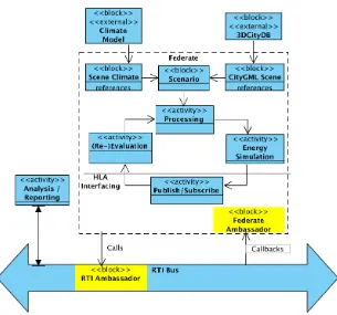
Figure 2 presents our proposed architecture forCitySim that adheres to the HLA architecture [14]. The internal components of CitySim architecture is 290
redesigned to follow a layered architecture [26] with the aim to minimize the software core modules dependency on the actual source of the data (e.g. from database or other tools). In the figures, we show external models that in-teract directly with CitySim marked with external. block refers to either external tool if marked accordingly, or to components that holds data 295
(e.g. scenario related data). The different high-level processes are marked with
activity, and the direction of the arrow refers to process dependency.
Two components are HLA-interface specific and their main purpose is to allow the federate responsible forCitySim to communicate with the platform. These components are highlighted in yellow in figure 2. The components are theRTI
300
ambassadors and the federate ambassador interfaces. The former is used to enable the federate (on behave of the simulator) to contact the RTI such as when a federate joins, for attribute updates and other interactions. The latter is used to receive callbacks from RTI (notifications from RTI) when the platform needs to contact the federate (e.g. to pass-over an instance of an interaction
305
class as defined in the FOM).
ap-Figure 2: Proposed layered integration architecture forCitySimover HLA.
proach we are considering is to define, for each of these two sources, a set of the data that are not changeable and a set that the federate receives updates 310
regarding (i.e. part of the FOM). The part that is fixed represent the core part of this data (e.g. when viewed on a specific time-scale) which will be fixed and used to initialize the instance of the simulator. This means that some informa-tion is expected to stay fixed during the actual simulainforma-tion time ofCitySim (i.e.
during a simulation for one year, the climate of the area will remain as described 315
in the input source for the whole year). The reason this assumption is attractive is that some of the phenomena that could lead to these changes takes longer time-cycle (i.e.more than one year, such as due to a climate change). Moreover, the computational costs for allowing the scene climate and geometry to change at arbitrary point could be very expensive. Note that some of these scene and 320
climate changes will be tackled as part of the workflow, such as (re)building parts of the city over time.
Now, we need to join the CitySim architecture into a workflow that inte-grate with the input data sources. We propose an end-to-end workflow shown in figure 3. The workflow presented show the individual sources for our 3D 325
[image:10.612.155.460.120.405.2]topographical survey and mapping of the whole Great Britain. For information about Energy-related properties and features of the buildings, we useInSmart
330
buildings typologies[27] along information processed from the “English Housing Survey”. Through the various transformations and fusing of data highlighted in the workflow, the data is transformed into a format suitable to stored in 3DCityDB instance. The 3DCityDB acts as a persistence storage for all the city data, and a platform for manipulating the city buildings and other physical 335
structures (e.g. constructing new building, roads or infrastructure). The policy and other interventions to the city will be planned (e.g. by appending temporal dimensions showing validity of the different objects stored in the SRDBMS) to reflect these changes to the 3D scene. A yearly snapshot of this data is then exported into a CityGML compliant format to be consumed by CitySim as 340
[image:11.612.133.552.292.522.2]discussed earlier.
Figure 3: Proposed workflow for analysing an urban scene withCitySim[7].
5. Conclusions
In this paper we have presented a workflow based on CitySim to perform micro-simulation of buildings’ energy performance at the urban scale. We con-trasted the two main approaches for integrating urban simulation tools, namely 345
resolved way for the city of Nottingham, which is coupled with other urban simulation tools (such as climate and transportation simulators).
350
We have described the ongoing work on developing the completed workflow and transforming building energy simulation tool to meet this vision as part of the Leverhulme project “Sustaining Urban Habitat-An Interdisciplinary Ap-proach”. Our future work will focus on realizing most of the development related to the HLA through developing the different ambassadors and also implementing 355
the new CityGML interface toCitySim to enable us to test various scenarios.
References
[1] U. Nation, United nation: world urbanization prospects: the 2014 revision, Tech. rep., UN Department of Economic and Social Affairs, New York NY (2014).
360
[2] A. Rasheed, D. Robinson, The urban climate, Computer Modelling for Sustainable Urban Design: Physical Principles, Methods and Applications 3 (2012) 57.
[3] W. D. Nordhaus, The ’dice’ model: Background and structure of a dy-namic integrated climate-economy model of the economics of global warm-365
ing, Tech. rep., Cowles Foundation for Research in Economics, Yale Uni-versity (1992).
[4] F. Haldi, D. Robinson, Interactions with window openings by office occupants, Building and Environment 44 (12) (2009) 2378 – 2395.
doi:http://dx.doi.org/10.1016/j.buildenv.2009.03.025. 370
URL http://www.sciencedirect.com/science/article/pii/ S0360132309000961
[5] V. Dorer, J. Allegrini, K. Orehounig, P. Moonen, G. Upadhyay, J. K¨ampf, J. Carmeliet, Modelling the urban microclimate and its impact on the en-ergy demand of buildings and building clusters, Proceedings of BS. 375
[6] T. H. Kolbe, G. Gr¨oger, L. Pl¨umer, Citygml: Interoperable access to 3d city models, in: Geo-information for disaster management, Springer, 2005, pp. 883–899.
[7] D. Robinson, F. Haldi, J. K¨ampf, P. Leroux, D. Perez, A. Rasheed, U. Wilke, Citysim: Comprehensive micro-simulation of resource flows for 380
sustainable urban planning, in: Proc. Building Simulation, Eleventh Inter-national IBPSA Conference, 2009, pp. pp. 1083–1090.
[8] C. F. Reinhart, C. C. Davila, Urban building energy modeling – a review of a nascent field, Building and Environment 97 (2016) 196 – 202.
doi:http://dx.doi.org/10.1016/j.buildenv.2015.12.001. 385
[9] R. NOUVEL, K.-H. BRASSEL, M. BRUSE, E. DUMINIL, V. COORS, U. EICKER, D. ROBINSON, Simstadt, a new workflow-driven urban en-ergy simulation platform for citygml city models, in: Proceedings of Inter-390
national Conference CISBAT 2015 Future Buildings and Districts Sustain-ability from Nano to Urban Scale, LESO-PB, EPFL, 2015, pp. 889–894.
[10] D. Robinson, Computer Modelling for Sustainable Urban Design: Physical Principles, Methods and Applications, Taylor & Francis, 2012.
[11] S. Sicklinger, V. Belsky, B. Engelmann, H. Elmqvist, H. Olsson, 395
R. W¨uchner, K.-U. Bletzinger, Interface jacobian-based co-simulation, In-ternational Journal for numerical methods in engineering 98 (6) (2014) 418–444.
[12] T. Blochwitz, M. Otter, M. Arnold, C. Bausch, H. Elmqvist, A. Junghanns, J. Mauß, M. Monteiro, T. Neidhold, D. Neumerkel, et al., The functional 400
mockup interface for tool independent exchange of simulation models, in: Proceedings of the 8th International Modelica Conference; March 20th-22nd; Technical Univeristy; Dresden; Germany, Link¨oping University Elec-tronic Press, 2011, pp. 105–114.
[13] K. M. Chandy, J. Misra, Distributed simulation: A case study in design 405
and verification of distributed programs, IEEE Transactions on Software Engineering SE-5 (5) (1979) 440–452. doi:10.1109/TSE.1979.230182.
[14] B. A. de Mello, F. R. Wagner, A standardized co-simulation backbone, in: M. Robert, B. Rouzeyre, C. Piguet, M.-L. Flottes (Eds.), SOC Design Methodologies: IFIP TC10 / WG10.5 Eleventh International Conference on 410
Very Large Scale Integration of Systems-on-Chip (VLSI-SOC’01) December 3–5, 2001, Montpellier, France, Springer US, Boston, MA, 2002, pp. 181– 192. doi:10.1007/978-0-387-35597-9_16.
URLhttp://dx.doi.org/10.1007/978-0-387-35597-9_16
[15] IEEE, Ieee standard for modeling and simulation (m&s) high level archi-415
tecture (hla)– framework and rules, IEEE Std 1516-2010 (Revision of IEEE Std 1516-2000) (2010) 1–38doi:10.1109/IEEESTD.2010.5553440. URLhttp://dx.doi.org/10.1109/IEEESTD.2010.5553440
[16] M. Awais, P. Palensky, A. Elsheikh, E. Widl, S. Matthias, The high level architecture rti as a master to the functional mock-up interface compo-420
nents, in: Computing, Networking and Communications (ICNC), 2013 In-ternational Conference on, 2013, pp. 315–320. doi:10.1109/ICCNC.2013. 6504102.
URLhttp://dx.doi.org/10.1109/ICCNC.2013.6504102
[17] H. Neema, J. Gohl, Z. Lattmann, J. Sztipanovits, G. Karsai, S. Neema, 425
cyber-physical systems, in: Proceedings of the 10 th International Model-ica Conference; March 10-12; 2014; Lund; Sweden, Link¨oping University Electronic Press, 2014, pp. 235–245.
430
URL https://wiki.isis.vanderbilt.edu/OpenC2WT/index.php/Main_ Page
[18] R. Fujimoto, Parallel and distributed simulation, in: Proceedings of the 2015 Winter Simulation Conference, WSC ’15, IEEE Press, Piscataway, NJ, USA, 2015, pp. 45–59.
435
URLhttp://dl.acm.org/citation.cfm?id=2888619.2888624
[19] G. Booch, Object-Oriented Analysis and Design with Applications (3rd Edition), Addison Wesley Longman Publishing Co., Inc., Redwood City, CA, USA, 2004.
[20] A. Stadler, C. Nagel, G. K¨onig, T. Kolbe, Making interoperability per-440
sistent: A 3d geo database based on citygml, in: J. Lee, S. Zlatanova (Eds.), 3D Geo-Information Sciences, Lecture Notes in Geoinformation and Cartography, Springer Berlin Heidelberg, 2009, pp. 175–192. doi: 10.1007/978-3-540-87395-2_11.
URLhttp://dx.doi.org/10.1007/978-3-540-87395-2_11
445
[21] V. Coors, Citygml energy ade – 3d city models for energy simulation on urban scale (2015).
URL http://en.wiki.energy.sig3d.org/images/upload/
3DGeoInfo-2015-Tutorial.pdf
[22] T. Becker, C. Nagel, T. H. Kolbe, Integrated 3d modeling of multi-utility 450
networks and their interdependencies for critical infrastructure analysis, in: Advances in 3D Geo-Information Sciences, Springer, 2011, pp. 1–20.
[23] P.-O. Siebers, P. Davidsson, Engineering agent-based social simulations: An introduction, Journal of Artificial Societies and Social Simulation 18 (3) (2015) 13.
455
URLhttp://jasss.soc.surrey.ac.uk/18/3/13.html
[24] S. Weart, The development of general circulation models of climate, Studies in History and Philosophy of Science Part B: Studies in History and Philosophy of Modern Physics 41 (3) (2010) 208 – 217, special Issue: Modelling and Simulation in the Atmospheric and Climate Sciences. 460
doi:http://dx.doi.org/10.1016/j.shpsb.2010.06.002.
URL http://www.sciencedirect.com/science/article/pii/ S1355219810000407
[25] W. C. Skamarock, J. B. Klemp, J. Dudhia, D. O. Gill, D. M. Barker, W. Wang, J. G. Powers, A description of the advanced research wrf version 465
2, Tech. rep., DTIC Document (2005).
[27] J. P. GOUVEIA, N. BILO, M. GARGIULO, G. GIANNAKIDIS, V. GREG ´ORIO, D. IRONS, V. NUNES, D. ROBINSON, J. SEIXAS, A. VALENTIM, Insmart–integrative smart city planning.
470

![Figure 3: Proposed workflow for analysing an urban scene with CitySim [7].](https://thumb-us.123doks.com/thumbv2/123dok_us/8663988.375670/11.612.133.552.292.522/figure-proposed-workow-analysing-urban-scene-citysim.webp)
