Removed material volume calculations in CNC milling
by exploiting CAD functionality
Panorios Benardos*
Department of Mechanical, Materials and Manufacturing Engineering, University of Nottingham, UK,
University Park, Nottingham NG7 2RD, UK Email: [email protected] *Corresponding author
George-Christopher Vosniakos
School of Mechanical Engineering,National Technical University of Athens, Greece, Heroon Polytehneiou 9, 15780 Athens, Greece Email: [email protected]
Abstract: Material removal volume calculations in machining processes are
important in a variety of milling simulation applications, including material removal rate estimation and machining force calculation. In this paper two different approaches are presented to this end, i.e., Z-maps and Boolean operations with solid models. The Z-map method is simple but results in large files and needs sophisticated routines to render acceptable accuracy. Boolean operations between accurate solid models of the tool and the workpiece is implemented on readily available CAD system application programming interface. Beside the computational load which is bound to the accuracy level, it requires a sufficient number of interpolated points through one revolution of the tool to be trustworthy. It is practical to use at particular points of interest along the toolpath.
Keywords: material volume; milling; Z-map; solid model; toolpath;
computer-numerical control.
Reference to this paper should be made as follows: Benardos, P. and
Vosniakos, G-C. (xxxx) ‘Removed material volume calculations in CNC milling by exploiting CAD functionality’, Int. J. Computer Aided Engineering and Technology, Vol. X, No. Y, pp.000–000.
Biographical notes: Panorios Benardos received his Diploma in Mechanical Engineering from the National Technical University of Athens in 2001. He was then engaged as a Researcher at the Manufacturing Technology Division and in 2009 he received his PhD for work on intelligent optimisation of sculptured surface machining and was appointed a contract Lecturer. From 2010, he has been a Senior Researcher at NTUA involved in various EU funded projects. In April 2014 he joined the University of Nottingham as Assistant Professor in Manufacturing Systems. He is the author of 25 publications.
Interfaces (1991) from UMIST (UK). He worked as a CIM R&D Project Manager in the German software industry, as a Lecturer at UMIST and as a Consulting Mechanical Engineer. In 1999, he joined NTUA as an Assistant Professor and since 2015 he is Professor. He has been involved in over 35 R&D projects with national, European and private funding. He is member of the editorial board of four international journals and has authored 153 publications.
1 Introduction
The volume of removed material in machining processes such as milling is necessary in studying these processes by geometric modelling approaches. The aims concern, among others, material removal rate calculation, mapping of rest material distribution on the workpiece surface, machined surface topography visualisation, possible collision determination as well as cutting force model development.
In general, two main classes of approaches may be distinguished, namely those based on solid modelling and on point-based discretisation. Solid modelling may be used to represent both the cutting tool and the workpiece, using constructive solid geometry (Spence and Altintas, 1994; Imani and Elbestawi, 2001), or boundary representation (El-Mounayri et al., 1998). Variations include use of discretised slices of the tool (Merdol and Altintas, 2008), envelope volume swept by the cutting edges (Sun et al., 2009; Layegh et al., 2012). This method offers considerable accuracy in determining their common (intersection) volume but at considerable computational cost, namely O(N4) for CSG and O(N1.5) for B-rep where N is the number of cutting tool motion segments (Bohez et al., 2003). In addition, volume representation variations to lower computational cost include octrees (Karunakaran et al., 2010) and dexels (Zhang et al., 2009).
Point-based methods include notably Z-map and discrete vector methods. Z-maps were introduced by Anderson (1978) regarding milling and were further developed and continually used until recently (Baek and Ko, 2008). A point network is created usually on the base of the workpiece and the workpiece height corresponding to any of these points is stored in an array. As the cutting tool moves over the point network the corresponding height is updated only if material is removed. This is easy to implement has low computational cost O(N) and allows material removal rate to be readily estimated. However, accuracy depends heavily on the network density and on workpiece orientation (Choi and Jerard, 1998). In a similar context, various point and curve-based discretisation methods have been used, too (Bouzakis et al., 2003). Discrete vector method represents workpiece surface at its various points using normal vectors (Chapel, 1983). The latter are intersected with the cutting tool motion envelope. The final length of the vector corresponds to removal of less or more material than anticipated, if the vector extends above or below the surface, respectively. This method is suited to 5-axis milling and allows material removal deviations from the ideal, but not direct calculation of material removal rate. In a similar context, various geometric analysis methods have been used, too (Tsai and Liao, 2010).
Material Removal Rate is calculated over one or more revolutions of the tool and does not take into account either the exact cutting edge geometry or the variation of entry and exit angle along the cutting edges. Instantaneous cutting forces may be calculated by mechanistic models discretising the cutting tool into slices and taking into account chip thickness as well as length (axial direction) and width (peripheral direction) (see e.g. Merdol and Altintas, 2008).
In this work, calculations of the material volume removed per revolution of the cutting tool are investigated, as reported in sections 2 to 4 in order to be used in force predictive neural models (Benardos and Vosniakos, 2014). This constitutes a challenge, especially in the presence of scallops on the workpiece owing to previous roughing passes, which make representation of the workpiece surface in a CAD system indispensable. In addition, the material removed should be identified at any point along the CNC toolpath, typically using position interpolation as briefly described in the next section. Results are presented in Section 5 and Conclusions in Section 6.
2 Calculation of toolpath points
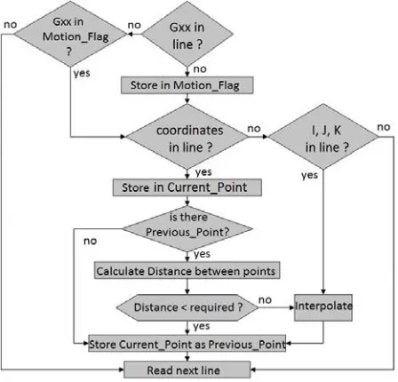
[image:3.612.195.419.410.625.2]The G-code corresponding to the milling path is read off an ASCII file line by line. Cutting movements are discriminated and further categorised by type of interpolation see Figure 1. Currently, straight lines (G01) and circular lines (G02 and G03 for clockwise and anti-clockwise) are supported, but any extension to encapsulate machine specific interpolation types is possible, e.g. spline, ellipse, hyperbolae etc.
Within each cutting movement the coordinates of two consecutive points are registered and if the length of the line connecting them is larger than a predefined value, then the corresponding interpolation routine is executed in order to calculate the appropriate number of intermediate points that form consecutive segments of equal length (except for – possibly – the last one). Linear and circular interpolation calculations are considered to be trivial and for this reason they are not presented here. The corresponding routines were written as a Matlab application. All coordinates of both existing and calculated points are stored in a file.
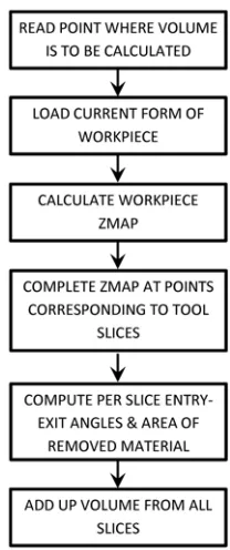
Figure 2 Material removal calculation logic using Z-maps
3 Removed material calculation by Z-maps
The Z-map method was implemented using Solidworks application programming interface (API) and Matlab according to the steps depicted in Figure 2.
see Figures 3(b)–3(d), the corresponding file sizes were 165 kB, 651 kB and 2,680 kB, confirming proportionality of the file size to the square of the point network distance. Thus, a distance of the order of 100 μm which is marginally acceptable results in a file size of 67 MB and a distance of 10 μm, which would be most certainly adequate would need 6.6 GB storage space, which is clearly excessive by any standards.
Figure 3 (a) Sample part (femoral implant) (b) Z-maps for point network distance equal to 2 mm (up), 1 mm (middle) and 0.5 mm (down)
(a)
A solution that was considered was to calculate Z-maps only locally, i.e. only around the cutting tool in order to reduce file size and computational load. However, in this way the Z-map could not be updated at regions from which material had already been removed, since the Z-map could not represent the whole of the workpiece.
[image:6.612.137.476.222.415.2]A further hindrance was due to the need to discretise the tool into finite thickness slices so as to calculate in detail the entry and exit angles for each one of them and from there the ‘peripheral’ area of engagement between tool and workpiece.
Table 1 Accuracy of Z-map compared to solid modelling
Engagement (mm2 × 10–6)
Part/endmill
Z-map Βoolean
Relative error
(%)
Ζ-map distance
(μm)
Z filling distance (μm)
Flat/flat 2.846 2.820 0.93 100 10
2.821 2.820 0.04 100 1
2.846 2.820 0.93 50 10
2.821 2.820 0.04 50 1
Flat/ball 3.132 3.210 –2.42 100 10
3.132 3.210 –2.43 100 1
3.174 3.210 –1.12 50 10
3.174 3.210 –1.14 50 1
Implant/ball 1.943 4.710 –58.75 100 10
1.637 4.710 –65.24 100 1
1.935 4.710 –58.92 50 10
1.515 4.710 –67.83 50 1
Figure 4 (a) Flat workpieces with flat and ball end mill and (b) freeform roughed workpiece with
ball end mill (see online version for colours)
(a) (b)
[image:6.612.206.408.453.601.2]was reduced since the slices would not be thin enough to warrant it. On the contrary, if the step was small the number of boundary points that would fall in the particular slice might be too small to guarantee accuracy of entry and exit angle calculation. An indication of the deviations of the calculated area using Z-maps compared to the calculations performed using solid modelling functions, as detailed in the next section, is given in Table 1. The relevant part/tool cases are depicted in Figure 4.
If part shape is simple accuracy attained is high, but in cases where part shape is complex the error is considerable. Thus, for reasons of both efficiency and accuracy the Z-map approach is abandoned in favour of the solid modelling approach which is described next.
4 Removed material calculation by solid models
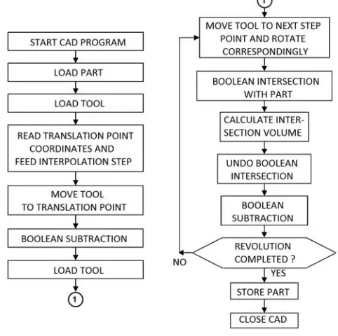
[image:7.612.184.425.359.599.2]This method is conducted in successive steps as shown in Figure 5. The main idea is to subtract the volume corresponding to the cutting tool from that of the workpiece at successive positions.
Figure 5 Calculation logic of material removal per revolution of the cutting tool using solid
models
as SolidcamTM. This is easily converted into a Brep format in any CAD system, including SolidworksTM in this case.
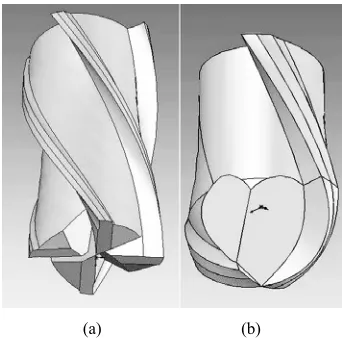
[image:8.612.220.391.238.407.2]The cutting tool is modelled using standard solid modelling techniques, too. Two cutting tools were parametrically modelled in this case, namely a flat end mill with four flutes and a ball end tool with two flutes, see Figure 6. Parametric modelling consists in controlling the shape of the tool by just a few parameter values, i.e. diameter, length, flute or helix angle, axial and radial rake angle, thus avoiding complete re-modelling of the tool from scratch.
Figure 6 (a) Flat end mill and (b) ball end mill models
(a) (b)
The positions at which removed material volume is to be calculated are derived by following the linear movement along the designated toolpath and corresponding rotary stepwise movement of the tool. At each step an intersection of the tool and the workpiece is performed. By adding up the common volume of all intersections for the number of positions that correspond to a full rotation of the tool, the total material volume to subtract from the workpiece is calculated.
For example, for linear feed f = 150 mm/min and spindle speed S = 5,000 RPM, the distance covered by the tool in one revolution is l = f / S = 0.03 mm/rev. Discretising this distance into four segments yields a step distance of 0.0075 mm.
The result is an accurate enough representation of the workpiece surface. In terms of implementation the calculation is implemented in SolidWorks by moving the tool in the successive positions within a full rotation and by using Boolean subtraction and intersection as well as the MassProperty.Volume commands of the Solidworks API.
At the rest of the points the workpiece needs to only be updated in order to reflect the state it is at after milling is performed. At these positions, workpiece updating is performed using a simplified model of the cutting tool for reasons of speed and efficiency. In this case a cylinder is used represent the flat endmill and a cylinder with hemispherical end to represent the ball endmill.
[image:9.612.184.425.275.464.2]Again, updating operations are performed using Boolean operators, i.e. a union of the solid volumes representing the consecutive positions of the simplified tool and subtraction from the workpiece solid, in order to reflect the shape of the workpiece up to the point of the toolpath preceding the specific point at which the detailed calculation concerning removed volume is to be performed. This was performed with Solidworks API, too, according to the steps depicted in Figure 7.
Figure 7 Workpiece updating logic using solid models
In terms of implementation, all Solidworks API routines were used in Visual Basic scripts of about 500 lines. These communicate with the toolpath point selection application, see Section 2, using files rather than system memory.
5 Results and discussion
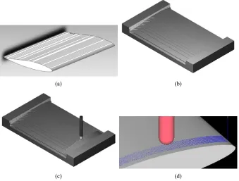
An aerodynamic vane is examined as a first example, in particular its pressure side, see Figure 8(a). This side was roughed using a flat end mill of 20 mm diameter following a hatch strategy, i.e. the cutting tool performed linear moves in a meander-like pattern on the XY plane, the horizontal distance of passes being 50% of the tool diameter and the vertical distance being 0.75 mm. The roughed shape of the vane is shown in Figure 8(b).
Figure 8 Aerodynamic vane, (a) shape (b) roughed (c) finish machining strategy
(d) finish machined (see online version for colours)
(a) (b)
(c) (d)
Interpolation step for calculating new points along the toolpath was 16 μm and the volume removed per revolution of the tool was calculated every 10 mm of toolpath length. The results corresponding to the first 1,500 mm of toolpath length (150 points) are shown in Figure 9.
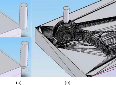
[image:10.612.188.423.492.661.2]A second example concerns the hemi-spherical head shown in Figure 10(a) of a femoral prosthesis shown Figure 3(a). Its roughing was performed with a flat end mill of 20 mm diameter using hatching with vertical distance of passes being set at 1 mm.
[image:11.612.138.475.218.342.2]Finish machining was conducted with a ball end mill of diameter 6 mm following profiling of the part on horizontal planes with a variable vertical step distance so as to keep scallop height below 10 μm, see Figures 10(b) and 10(c). Feed and speed were again set to 200 mm/min and 3,000 RPM.
Figure 10 Femoral head, (a) roughed (b) finish machined (c) finish machining strategy (see online version for colours)
(a) (b) (c)
Material removal was calculated with exactly the same conditions as in the previous example, but for 3,350 instead of 1,500 mm toolpath length and results are shown in Figure 11.
Figure 11 Volume per revolution calculations at 330 points of the toolpath for femoral head finishing
[image:11.612.140.437.399.594.2]Speed and accuracy of the calculation depend almost entirely on the size and quality of the file representing the workpiece model. It this is expressed in stl format, as was the case in this work, this reduces to the number of triangles constituting the model. However, the latter can be expressed in any other format available, e.g. sat, step etc, making use of a closed form representation of the boundary surfaces of the part.
Nevertheless, the stl format is considered suitable for expressing the roughed shape of the part not especially since most CAM systems support it as a universal format for expressing intermediate forms of the part from its initial to its final shape. Indicatively, a linear relationship between computation time in msec (t) and number of triangles (n) was recorded of the type: t = α * n – β, where α = 0.361 and β = 130.85 on an Intel i5TM processor.
These calculations may be further used for MRR estimation or for estimation of the cutting forces after suitable calibration. In terms of chip dimensions within this method the axial and peripheral engagement dimensions are accurately calculated. However, chip thickness is only approximated, but the approximation gets better as the number of discretisation points in a complete revolution is increased, typically 24 to 12, corresponding to a rotation of 15° to 30°. This is technically possible but is practical only for a few positions.
6 Conclusions
The material removed per revolution by the cutting tool in end milling operations needs to be calculated for various reasons, among others, to estimate material removal rate and the economics of a milling operation, calculate the dimensions of the chip, estimate the cutting forces etc.
The Z-map method is simple in principle but results in large files or, in order to rectify this, it needs to become more sophisticated, thereby losing its simplicity. The main difficulty arises when the workpiece needs to be updated to reflect the material removed during machining and is due to the curve-based representation of the tool.
This is circumvented by solid modelling based on Boolean operations between accurate models of the tool and the workpiece. Beside the computational load which is bound to the accuracy level, it requires a sufficient number of interpolated points through one revolution of the tool to be trustworthy. It is practical to use at particular points of interest along the toolpath but it is impractical to cover the whole of the latter.
In any case, the CNC toolpath needs to be calculated based on the relevant G-code and subsequently discretised using interpolation methods. The points of interest at which the detailed volume calculation of the removed material needs to be performed are to be selected either manually or automatically based on suitable criteria pertinent to the kind of further use that these calculations are planned for.
Acknowledgements
References
Anderson, R.O. (1978) ‘Detecting and eliminating collisions in NC machining’, Computer-Aided Design, Vol. 10, No. 4, pp.231–237.
Baek, D.K. and Ko, T.J. (2008) ‘Feedrate scheduling for free-form surface using an NC verification model’, International Journal of Machine Tools and Manufacture, Vol. 48, No. 2, pp.163–172.
Benardos, P. and Vosniakos, G-C. (2014) ‘Off-line flexible optimisation of feed and speed in CNC machining of sculptured surfaces exploiting dedicated cutting force metamodels’, Proc. of the Institution of Mechanical Engineers, Part B: Journal of Engineering Manufacture, Vol. 228, No. 6, pp.878–892.
Bohez, E.L.J., Minh, N.T.H., Kiatsrithanakorn, B., Natasukon, P., Ruei-Yun, H. and Son, L.T. (2003) ‘The stencil buffer sweep plane algorithm for 5-axis tool path verification’,
Computer-Aided Design, Vol. 35, No. 12, pp.1129–1142.
Bouzakis, K-D., Aichouh, P. and Efstathiou, K. (2003) ‘Determination of the chip geometry, cutting force and roughness in free form surfaces finishing milling, with ball end tools’,
International Journal of Machine Tools and Manufacture, Vol. 43, No. 5, pp.499–514. Chapel, I.T. (1983) ‘The use of vectors to simulate material removed by numerically controlled
milling’, Computer-Aided Design, Vol. 15, No. 3, pp.156–158.
Choi, B.K. and Jerard, R.B. (1998) Sculptured Surface Machining, Theory and Applications, Kluwer Academic Publishers, London.
El-Mounayri, H., Spence, A.D. and Elbestawi, M.A. (1998) ‘Milling process simulation – a generic solid modeller based paradigm’, Journal of Manufacturing Science and Engineering, Vol. 120, No. 2, pp.213–221.
Imani, B.M. and Elbestawi, M.A. (2001) ‘Geometric simulation of ball-end milling operations’,
Journal of Manufacturing Science and Engineering, Vol. 123, No. 5, pp.177–184.
Karunakaran, K.P., Shringi, R., Ramamurthi, D. and Hariharan, C. (2010) ‘Octree-based NC simulation system for optimization of feed rate in milling using instantaneous force model’,
The International Journal of Advanced Manufacturing Technology, Vol. 46, Nos. 5–8, pp.465–490.
Layegh, S.E.K., Erdim, H. and Lazoglu, I. (2012) ‘Offline force control and feedrate scheduling for complex free form surfaces in 5-axis milling’, Procedia CIRP, Vol. 1, pp.96–101.
Merdol, S.D. and Altintas, Y. (2008) ‘Virtual cutting and optimization of three-axis milling processes’, International Journal of Machine Tools and Manufacture, Vol. 48, No. 10, pp.1063–1071.
Spence, A.D. and Altintas, Y. (1994) ‘A solid modeller based milling process simulation and planning system’, Journal of Engineering for Industry, Vol. 116, No. 1, pp.61–69.
Sun, Y., Ren, F., Guo, D. and Jia, Z. (2009) ‘Estimation and experimental validation of cutting forces in ball-end milling of sculptured surfaces’, International Journal of Machine Tools and Manufacture, Vol. 49, No. 15, pp.1238–1244.
Tsai, C.L. and Liao, Y.S. (2010) ‘Cutting force prediction in ball-end milling with inclined feed by means of geometrical analysis’, The International Journal of Advanced Manufacturing Technology, Vol. 46, Nos. 5–8, pp.529–541.