Spherical Vortices in Rotating Fluids
By M. M. S C A S E & H. L. T E R R Y
School of Mathematical Sciences, University of Nottingham, Nottingham NG7 2RD (Received 30 January 2018; revised 9 April 2018; accepted 15 April 2018)
A popular model for a generic fat-cored vortex ring or eddy is Hill’s spherical vortex (Phil. Trans. Roy. Soc. A vol. 185, 1894, p. 213). This well-known solution of the Eu-ler equations may be considered a special case of the doubly-infinite family of swirling spherical vortices identified by Moffatt (J. Fluid Mech. vol. 35(1), 1969, p. 117). Here we find exact solutions for such spherical vortices propagating steadily along the axis of a rotating ideal fluid. The boundary of the spherical vortex swirls in such a way as to exactly cancel out the background rotation of the system. The flow external to the spherical vortex exhibits fully nonlinear inertial wave motion. We show that above a crit-ical rotation rate, closed streamlines may form in this outer fluid region and hence carry fluid along with the spherical vortex. As the rotation rate is further increased, further concentric ‘sibling’ vortex rings are formed.
1. Introduction
In 1894 Hill published his famous solution for the steady flow of a spherical vortex in an ideal fluid (Hill 1894). The solution consists of an inner rotational spherical region of fluid that matches onto an outer irrotational region of fluid that extends to infinity. Hill’s solution was later shown to be the end member of a family of steadily propagating vortex rings (Norbury 1973) of varying core thickness that includes ‘thin-cored’ rings (see Fraenkel 1970, 1972) where the rotational fluid is confined within a narrow region that does not extend to the axis. These solutions, in particular Hill’s, have been the focus of a number of stability analyses (see e.g., Moffatt & Moore 1978; Pozrikidis 1986; Protas & Elcrat 2016) that show that in time fluid may be detrained or entrained into the vortex according as to whether it has a prolate or oblate deformation respectively. Hill’s spherical vortex may also be viewed as a special non-swirling member of a doubly-infinite family of swirling spherical vortices identified by Moffatt (1969) that may be matched onto an oncoming irrotational stream. Here we show how this family of spherical vortices may be matched onto an oncoming stream in a rotating fluid.
2 M. M. Scase & H. L. Terry
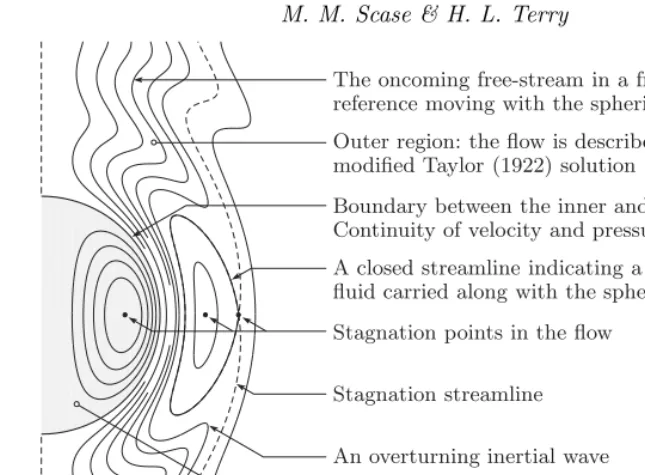
The oncoming free-stream in a frame of reference moving with the spherical vortex
Outer region: the flow is described by the modified Taylor (1922) solution
Boundary between the inner and outer flows. Continuity of velocity and pressure is enforced
A closed streamline indicating a region of outer fluid carried along with the spherical vortex
Stagnation points in the flow
Stagnation streamline
An overturning inertial wave
[image:2.595.74.396.51.288.2]Inner region: the flow is described by the non-precessing Hill (1894) or Moffatt (1969) solutions
Figure 1: Schematic of the flow in a frame of reference moving with the spherical vortex. The grey inner region consists of either the non-precessing Hill (1894) or Moffatt (1969) solutions. This inner region matches onto a rotating outer region that is given by a modified version of the solution presented by Taylor (1922). At the boundary between the inner and outer regions continuity of velocity and pressure is enforced.
that resembled Hill’s spherical vortex could be observed in the flow, though he described this analogy between his flow and Hill’s spherical vortex as ‘only superficial’.
In the present work we combine the approach of Taylor (1922) (summarized briefly in §2.1) with the solutions of Hill (1894) in§2.2 and Moffatt (1969) in §2.3 to find exact solutions of the rotating Euler equations for a spherical vortex propagating steadily along the axis of rotation where, like Taylor’s sphere, the boundary of the spherical vortex does not precess in the laboratory frame. The flow, in a frame of reference moving with the spherical vortex, is shown schematically in figure 1. The inner solution, given by either Hill (1894) or Moffatt (1969), is shown in grey. This inner solution for the spherical vortex is matched onto a modified Taylor (1922) solution in the outer region by enforcing continuity of velocity and pressure across the boundary. The flow in the outer region exhibits inertial waves that above critical rotation rates may overturn. In§2.4 we show that as the rotation rate of the system is increased above these critical rotation rates, closed streamlines form in the outer fluid representing a series of thin-cored ‘sibling’ vortex rings, propagating with the spherical vortex. In§3 we draw our conclusions.
2. Spherical Vortices in Rotating Fluids
thatθ= 0 is in the ˆz-direction. We seek to model a spherical vortex of constant radiusa
and constant propagation velocityUzˆ, hence we nondimensionalize position asx=ax˜, velocity as u = Uu˜, and pressure asp = ρU2p˜, where tildes indicate nondimensional
quantities. Dropping the tildes immediately the nondimensional steady rotating Euler equations that govern the motion are
∇ ·u= 0, (u· ∇)u=−∇p+ r 4Ro2ˆr−
1
Rozˆ×u, Ro =
U
2aΩ, (2.1a–c) where: we have defined a Rossby number, Ro; ˆr= sinθσˆ+ cosθθˆ is a unit vector in the cylindrical radial direction, andr=σsinθis the cylindrical radial position.
2.1. Taylor’s Solution
Taylor (1922) considered the axisymmetric flow around a non-precessing sphere (in the laboratory frame) that is translating steadily with nondimensional velocity ˆz through a fluid rotating steadily about ˆz. This flow may be described by defining an axisymmetric streamfunction, ψ(σ, θ), as in Batchelor (1967), and writing the velocity in the radial, polar and azimuthal directions respectively as
u= 1
σ2sinθ
∂ψ
∂θ, v=−
1
σsinθ ∂ψ
∂σ, w=−
1 Ro
ψ
σsinθ + σsinθ
2
. (2.2a–c)
(The second term in brackets in the expression forwis included here as we are working in the non-inertial frame of reference of the rotating fluid.) The incompressibility condition (2.1a) is automatically satisfied. Taylor (1922) proceeded by posing that the streamfunc-tion be of the separable formψ =f(σ) sin2θ. Substitution into the curl of (2.1b), thus removing the pressure gradient, leads to either the trivial solutionf = 0 or thatf must satisfy
σ3f′′′
−2σ2f′′
−2σf′
+ 8f+ σ
2
Ro2(σf
′
−2f) = 0, (2.3)
where a dash denotes differentiation with respect to σ. In the frame of reference rotat-ing with the fluid, but translatrotat-ing with a sphere of radius δ that is not precessing in the laboratory frame, the no-normal flow and no-precession boundary conditions on the boundary of the sphere, together with the far-field velocity boundary condition, are
u(δ, θ) = 0, w(δ, θ) =−δsinθ
2Ro , σlim→∞u(σ, θ) = (−cosθ,sinθ,0). (2.4a)
Equivalently, in terms off
f(δ) = 0, lim
σ→∞
f(σ)
σ2 =−
1
2. (2.4b)
The pressure field is given by
p(σ, θ) =
2f f′′
−f′2+ f2
Ro2
sin2θ 2σ2 −
2f2
σ4 +
1
2, (2.5)
where the pressurep→(8Ro2)−1σ2sin2θ, the hydrostatic pressure field, asσ→ ∞. The
vorticity field,ω≡ ∇ ×u, is
ω=− 1 Ro
cosθ
2f σ2 + 1
ˆ σ−sinθ
f′
σ + 1
ˆ θ
−sinθ
σ
f′′
−2f σ2
ˆ
4 M. M. Scase & H. L. Terry
-2 -1 0 1 2
0 1 2 3 4
z
r
0 1 2 3
r
[image:4.595.50.430.49.272.2](a) (b)
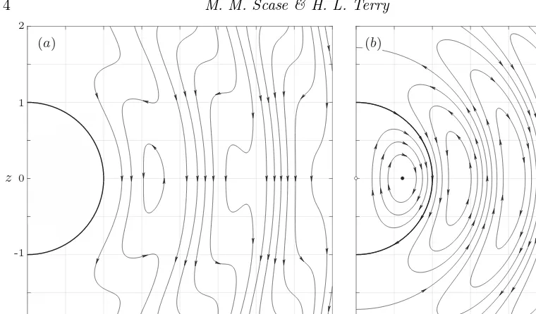
Figure 2: (a) Streamlines around a unit sphere translating steadily along the axis of rotation (r= 0) of a rotating fluid in the reference frame of the sphere. Closed streamlines show that fluid is being transported with the sphere. (b) Streamlines around a sphere of vanishing size (white circle at the origin) translating steadily along this axis of rotation of a rotating fluid in the frame of reference of the main body of fluid. Taylor (1922) observed that the streamlines near the origin resemble those of a Hill’s spherical vortex (Hill 1894) but described the analogy between the flow and a spherical vortex as ‘only superficial’.
The solution to (2.3) that satisfies (2.4b) may be written as
f(σ) =−σ
2
2 + 1 2σ
δ3+c(σ−δ) cos
σ−δ
Ro
+
δ3σ−c δσ+ Ro2
Ro sin
σ−δ
Ro )
, (2.7)
for an arbitrary constantc. The remaining no-slip boundary condition in the polar direc-tion,v(δ, θ) = 0, is satisifed whenf′
(δ) = 0 forcingc=δ2−3Ro2, and this together with
(2.7) can be shown to be equal to Taylor’s solution. The no-precession condition and the no-slip boundary condition in the polar direction are physically motivated choices to close the system. The conditions are no-slip conditions applied to an inviscid fluid in the expectation that the inviscid solution will closely approximate the full viscous solution where no-slip conditions would be rigorously valid.
The streamlines forδ= 1, Ro = (2π)−1are shown in figure 2a. The nonlinear wavefield
forcing along the axis of a rotating fluidinto initially quiescent fluid and concluded that only columnar modes could exist ahead of the forcing.
Taylor (1922) observed that his analytical solution still exhibited waves even in the limit that the sphere has a vanishingly small radius, i.e., in the limitδ→0. Figure 2b shows this solution, in the laboratory frame of reference. The sphere is instantaneously located at the origin, indicated by a white circle. Taylor (1922) observed that the streamlines near the origin resemble those of a Hill’s spherical vortex (Hill 1894). Here the rotation rate has been chosen such that this apparent spherical vortex has a unit radius (given by the largest Ro that satisfies Ro sin(Ro−1) = cos(Ro−1), i.e., Ro
≈0.223). The boundary of the apparent spherical vortex is shown in bold. Taylor (1922) describes this analogy with Hill’s spherical vortex as superficial as the vortex can only exist when the flow is rotating and a vanishingly small sphere is translating steadily, without precession, along the axis of rotation.
2.2. Hill’s spherical vortex in a rotating fluid
The classical Hill’s spherical vortex is a spherical region of rotational fluid that propagates through an irrotational ambient fluid. The flow is found by constructing solutions inside and outside the spherical vortex and enforcing pressure and velocity continuity across the boundary of the two regions. As with the no-slip conditions enforced on the solid sphere in Taylor’s solution, continuity of velocity is enforced across the boundary of the two inviscid solutions, even though this is not a strict requirement, in the expectation that the solution will closely approximate the behaviour of a real viscous fluid. In a frame of reference moving with the spherical vortex, Hill’s solution is given by
u=
3 cosθ
2 (1−σ
2) ˆσ−3 sinθ
2 (1−2σ
2)ˆθ σ61
−cosθ σ3 (σ
3−1) ˆσ+sinθ
2σ3(2σ
3+ 1)ˆθ σ >1.
(2.8a) p=
−9σ
2(3−2σ2)
8 sin
2θ+9σ2(2−σ2)
8 −
5
8 σ61 −3(4σ
3−1)
8σ6 sin
2θ+2σ3−1
2σ6 σ >1.
(2.8b)
where the arbitrary pressure constant has been chosen without loss of generality such that p→0 as σ→ ∞. The solution is in the frame of reference of the spherical vortex and so the velocity in the far-field tends to−zˆ. The solution is axisymmetric and swirl-free and the velocity can be represented by a streamfunction,ψ, of the form of (2.2a–b), where ψ=
3σ2(1−σ2)
4 sin
2θ σ61
−(σ
3−1)
2σ sin
2θ σ >1
(2.9)
and w= 0. The arbitrary constant that may be added to the streamfunction is chosen such thatψ= 0 on the boundary of the spherical vortex. The pressure and velocity fields are continuous across the boundary of the spherical vortex,σ= 1.
We now make the following observation; ifu(σ, θ) together with a corresponding pres-sure field,p(σ, θ), solves the non-rotating Euler equations and ucan be represented by a streamfunctionψ(σ, θ) in the form of (2.2a–b) withw= 0, then
u=
1
σ2sinθ
∂ψ ∂θ,−
1
σsinθ ∂ψ ∂σ,−
σsinθ
2Ro
6 M. M. Scase & H. L. Terry
solves the rotating Euler equations with the same pressure field p. This is because the swirling component in (2.10),w=−(2Ro)−1σsinθ, exactly cancels the background
ro-tation of the fluid. Thus, we have that (2.10) with ψ given by Hill’s inner non-rotating solution ((2.9) forσ61), and the pressure,p((2.8b) for σ61) automatically satisfies the incompressibility condition and the rotating equations of motion (2.1a–b). The solu-tion is Hill’s non-rotating spherical vortex described in a rotating frame of reference. To distinguish this solution from the classical solution we refer to it as the ‘swirling’ Hill’s spherical vortex, even though the azimuthal component of the velocity field exactly can-cels the background rotation of the fluid. The observation that Taylor’s sphere in his experiments did not precess about the axis of rotation gives rise to the possibility that there may exist a form of Taylor’s solution that can be matched onto the swirling Hill’s spherical vortex by enforcing a different choice of polar velocity boundary condition to Taylor’s no-slip condition when settingcin (2.7).
To match a solution of the form (2.2) onto the swirling Hill’s spherical vortex such that the velocity field is continuous across the boundaryσ= 1, we require a solution to (2.3) that satisfies, forδ = 1, the conditions (2.4b) and yields v(1, θ) = 3
2sinθ. We therefore
requiref′
(1) =−32 and hence the solution is given by (2.7) withδ= 1,c= 1, so that
f(σ) =−σ
2
2 + 1 2σ
σcos
σ −1 Ro
−Ro sin σ
−1 Ro
. (2.11)
Substitution of this solution atσ= 1 into (2.5) shows that the pressure on the boundary is given byp(1, θ) = 12−98sin2θ, exactly matching the pressure on the boundary of the swirling Hill’s spherical vortex (see (2.8b) atσ= 1). The solution has the property that Hill’s classical solution is recovered in the limit Ro → ∞. Thus, we have a complete steady solution to the nonlinear rotating Euler equations whose inner solution is Hill’s spherical vortex with an additional swirling component in the azimuthal direction that cancels out the background rotation of the fluid. This inner solution matches onto an outer solution, with continuous velocity and pressure across the boundary of the vortex. In the far-field the velocity tends to the free-stream velocity−ˆzand pressure tends to the hydrostatic pressure fieldp= (8Ro2)−1σ2sin2θ. We observe thatψis even in the Rossby
number and so the waves that form in a meridional plane (φ= const.) oscillate according only to the magnitude of the rotation of the system, and not the sign of the direction of rotation, as might be expected on physical grounds. Similarly, as a result of (2.2c) and (2.11), the azimuthal velocity is odd in the Rossby number and so the azimuthal flow field is reversed if the sign of the direction of rotation of the system is reversed. We see from (2.11) that the wavelength of the inertial waves in the outer fluid is 2πRo as in Taylor (1922).
Figure 3(a)–(c) shows streamlines in the (r, z) meridional plane of Hill’s spherical vortex and the flow outside the spherical vortex for three different values of the Rossby number. The streamlines represent the flow relative to the translating spherical vortex. The meridional velocity components are always zero atr = 2−1/2, z = 0, indicated by
-4 -3 -2 -1 0
0 1 2 3 4
1 2 3 4
r
(a)
z
0 1 2 3 4
r
(b)
0 1 2 3 4
r
(c)
(d)
z
r
-1 0 1
0 1 2 3
(e)
r
0 1 2 3
(f)
r
[image:7.595.59.425.48.432.2]0 1 2 3
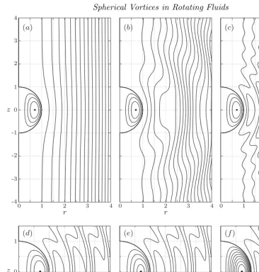
Figure 3: (a)–(c): Plots of the streamfunction for Hill’s spherical vortex for Ro = ∞,
1 4,
1
10 for (a)–(c) respectively. The meridional stagnation point in the spherical vortex
is indicated by a small black circle and is located at r = 2−1/2, z = 0. In plot (c)
the formation of closed streamlines externally to the spherical vortex may be observed, indicating regions of fluid that are transported with the spherical vortex. (d)–(f): Plots of the streamfunction for swirling spherical vortices for Ro = 101. The parameters shown are: (d)α= 0, λ= 152 (Hill’s spherical vortex); (e)α=π2,λ=152; (f)α= π2,λ= 15.
2.3. Swirling spherical vortices in a rotating fluid
We now generalize the method of§2.2 for the family of swirling spherical vortices iden-tified by Moffatt (1969). The spherical vortex, for σ 6 1, is described in terms of a streamfunction by
u= 1
σ2sinθ
∂ψ
∂θ, v=−
1
σsinθ ∂ψ
∂σ, w=− α ψ σsinθ−
σsinθ
2Ro . (2.12)
doubly-8 M. M. Scase & H. L. Terry infinite family of spherical vortices given by
F(σ) = λ
α2
σαcos(σα)
−sin(σα)
σ(αcosα−sinα) −σ
2
. (2.13)
The corresponding pressure field is given by (2.5) withf replaced byF and Ro replaced byα−1. It follows from (2.12) thatαis a measure of the degree of swirl in the spherical
vortex. The special case of Hill’s spherical vortex ring is recovered in the limit α→0,
λ = 15
2. No-normal flow and no-precession conditions are satisfied on the boundary
of the swirling spherical vortices as F(1) = 0, and hence u(1, θ) = 0 and w(1, θ) = −(2Ro)−1sinθ. The conditions of continuity of pressure and polar velocity across the
boundary are satisfied if a solution forf, given by (2.7) withδ= 1, can be found such thatf′
(1) =F′
(1) and this condition is satisfied when
c= 1 + 2Ro2 λ
α2
3 + α
2sinα
αcosα−sinα
−3 2
. (2.14)
(Note that the result of§2.2,c= 1, is recovered in the limitα→0,λ= 152.) Hence, any swirling spherical vortex given by (2.12) and (2.13) may be matched onto an oncoming stream in a rotating fluid whose far-field velocity tends to−zˆ with continuous pressure and velocity across the boundary of the spherical vortex atσ= 1. We also see that the outer flow is a singly-infinite family given by (2.14) and is equal to the outer flow of the swirling Hill’s spherical vortex solution for all solutions withc= 1, i.e., for all (λ, α)∈R2 such that the quantity in square brackets in (2.14) is zero.
Figure 3(d)–(f) shows streamlines in the (r, z) meridional plane of the swirling spherical vortices for Ro = 1
10 and: (d)α= 0, λ= 15
2 Hill’s swirling spherical vortex; (e)α= π 2,
λ= 15
2; (f)α= π
2,λ= 15. It can be seen that the stronger of the two swirling Moffatt
solutions (f) corresponds to a larger amplitude wavefield in the outer fluid, with three closed streamlines in the image shown.
2.4. Sibling vortices
The critical rotation rate at which the onset of overturning is observed may be found by considering the turning points of the streamlines. If a given streamline, ψ = const. for σ > 1, is parameterized byθ = θ(σ) then a necessary condition for overturning is dθ(σ)/dσ= 0, that is, when
2Ro2σ3+
Ro2σ+ (c−1)
σ2+ Ro2(σ
−1) cos σ
−1 Ro
+
σ2−Ro2−(c−1)
Ro2−σ(σ−1) sin σ
−1 Ro
= 0. (2.15a)
This expression has a different number of branches of solution for a given Rossby number, Ro, as is shown in figure 4a forc = 1. There is therefore in this case a minimum rate of rotation below which no closed streamlines in the outer fluid are formed and no fluid is carried along with the spherical vortex. The first critical rotation rate occurs when dRo(σ)/dσ= 0 where Ro = Ro(σ) is determined by (2.15a). This condition is given by
6Ro3σ+ Ro [σ+ (c−1)(σ+ 1)] cos σ
−1 Ro
+
Ro2+ (c−1)(Ro2−σ) sin
σ −1 Ro
σ Ro
(a)
0.05 0.10 0.15 0.20 0.25
1 2 3 4 5 6
-12 -10 -8 -6 -4 -2 0
1 2 3 4 5 6
ψ
[image:9.595.53.430.48.193.2]σ (b)
Figure 4: (a) Zeros of (2.15a) forc= 1; as the rotation rate increases the Rossby number, Ro, decreases and new branches of the solution are found. The critical rotation rates at which new branches of solution are found are given by zeros of the system (2.15), indicated by circles. The fifth critical Rossby Ro = Ro(5)c ≈0.114 is indicated by the black circle.
(b) The streamfunction forθ=π/2 and Ro = Ro(5)c . This plot corresponds to the z= 0
transect of figure 5. The black circles that occur at local minima in ψ correspond to black stagnation points in figure 5. The white circles that occur at local maxima inψ
correspond to the white stagnation points in figure 5. Forψlying between pairs of black and white turning points, indicated by the grey regions, the functionσ(ψ) is multi-valued and this corresponds to closed streamlines in the flow. At the chosen Rossby number the fifth set of closed streamlines is about to appear at the inflection point indicated by the dashed line, corresponding to the cusp atr≈4.39 (black-white circle) in figure 5.
The critical points determined by simultaneous solutions of (2.15a) and (2.15b) are shown for c = 1 as circles in figure 4a and we denote the critical Rossby numbers as Ro = Ro(n)c and the corresponding critical radii as σ = σ
(n)
c for n = 1,2,3, . . .. The first
critical rotation rate, Ro(1)c , that represents the minimum rotation rate for which a closed
streamline forms in the flow is found numerically, for Hill’s spherical vortex, to be Ro(1)c ≈ 0.239. This rotation rate lies between those shown in figure 3band 3c. The corresponding radius,σc(1)≈2.07 andθ=π/2 gives the location at which the overturning first occurs.
For a given Rossby number, the associated number of branches of solutions of (2.15a) corresponds to the number of closed streamlines in the flow outside the spherical vortex, and hence corresponds to the number of regions of fluid that are advected with the spherical vortex.
The value of the streamfunction on the closed streamlines and the location of stagnation points in the flow can be found by consideringψonθ=π/2. Figure 4bshowsψ(σ, π/2) for σ > 1 and Ro = Ro(5)c ≈ 0.114, the fifth critical rotation rate (indicated by the
black circle in figure 4a). The turning points inψcan be seen to appear in pairs of local minima (black circles) and local maxima (white circles). For values ofψbetween the local minima and maxima, indicated by the grey bands, the functionσ(ψ) is multi-valued and this corresponds to closed streamlines in the flow. As the flow considered is exactly at the fifth critical rotation rate, the fifth pair of local minima and maxima coincide at the inflection inψwhere σ≈4.39 andψ≈ −9.65.
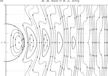
Figure 5 shows streamlines of the flow for a swirling Hill’s spherical vortex in a rotating fluid at Ro = Ro(5)c corresponding to the rotation rate in figure 4b. The stagnation point
10 M. M. Scase & H. L. Terry
0 1 2 3 4 5 6
r -2
-1 0 1 2
[image:10.595.52.427.50.312.2]z
Figure 5: A meridional slice through the flow field in the frame of reference moving with a swirling Hill’s spherical vortex ring for Ro = Ro(5)c ≈0.114. This is the fifth critical
Rossby number, we can see four sibling vortex rings (bold lines) have been created in the outer fluid and there is a cusp that has formed (black-white circle atr≈4.39, z= 0) on a streamline that will form the next sibling vortex ring when Ro<Ro(5)c .
flow there can be seen to be four closed streamlines, indicated in bold. We observe that the direction of advection around these closed streamlines (anti-clockwise) is opposite to that in the spherical vortex (clockwise), though the vorticity in the closed streamlines may change sign (see (2.6)). The black stagnation points in the closed streamlines correspond to the black local minima in figure 4b. The white stagnation points, on the boundary of the closed streamlines, correspond to the local maxima in 4b. A fifth ‘closed streamline’ is about to form at the cusp indicated by the black-white circle at σ ≈ 4.39. This corresponds to the inflection inψin figure 4b.
3. Conclusions
As the rotation rate is increased the amplitude of the waves is observed to grow until, at a critical rotation rate wave-overturning may be observed and closed streamlines form in the outer fluid. The closed streamlines represent vortex rings that are concentric to the spherical vortex on the axis and which propagate with the spherical vortex. As the ro-tation rate is increased beyond subsequent critical Rossby numbers, new ‘sibling’ vortex rings are added to the vortex ring family propagating along the axis of rotation.
The authors would like to thank an anonymous referee for drawing our attention to the solutions of Moffatt (1969).
REFERENCES
Batchelor, G. K.1967 An introduction to fluid dynamics. Cambridge University Press.
Eisenga, A. H. M.1997 Dynamics of a vortex ring in a rotating fluid. PhD thesis, Eindhoven University of Technology.
Fraenkel, L. E. 1970 On steady vortex rings of small cross-section in an ideal fluid. Proc. Roy. Soc. A316, 29–62.
Fraenkel, L. E.1972 Examples of steady vortex rings of small cross-section in an ideal fluid. J. Fluid Mech.51, 119–135.
Hill, M. J. M.1894 On a spherical vortex. Phil. Trans. Roy. Soc. A185, 213–245.
Lighthill, M. J.1967 On waves generated in dispersive systems by travelling forcing effects, with applications to the dynamics of rotating fluids. J. Fluid Mech.27(4), 725–752.
Moffatt, H. K.1969 The degree of knottedness of tangled vortex lines.J. Fluid Mech.35(1), 117–129.
Moffatt, H. K. & Moore, D. W.1978 The response of Hill’s spherical vortex to a small axisymmetric disturbance. J. Fluid Mech.87(4), 749–760.
Norbury, J.1973 A family of steady vortex rings. J. Fluid Mech.57(3), 417–431.
Pozrikidis, C.1986 The nonlinear instability of Hill’s vortex. J. Fluid Mech.168, 337–367.
Protas, B. & Elcrat, A.2016 Linear stability of Hill’s vortex to axisymmetric perturbations. J. Fluid Mech.799, 579–602.
Stewartson, K. 1958 On the motion of a sphere along the axis of a rotating fluid Q. J. Mech. Appl. Math.11(1), 39–51.
Taylor, G. I.1922 The motion of a sphere in a rotating liquid. Proc. Roy. Soc. A102(715), 180–189. 1922.
Verzicco, R., Orlandi, P., Eisenga, A. H. M., van Heijst, G. J. F. & Carnevale, G. F.