warwick.ac.uk/lib-publications
Original citation:
Sellamuthu, Prabhukumar, Samuel, D. G. Harris , Dinakaran, D., Premkumar, V. P., Li, Zushu
and Seetharaman, Sridhar (2018) Austempered ductile iron (ADI) : influence of austempering
temperature on microstructure, mechanical and wear properties and energy consumption.
Metals, 8 (1). 53.
doi:10.3390/met8010053
Permanent WRAP URL:
http://wrap.warwick.ac.uk/97246
Copyright and reuse:
The Warwick Research Archive Portal (WRAP) makes this work of researchers of the
University of Warwick available open access under the following conditions.
This article is made available under the Creative Commons Attribution 4.0 International
license (CC BY 4.0) and may be reused according to the conditions of the license. For more
details see:
http://creativecommons.org/licenses/by/4.0/
A note on versions:
The version presented in WRAP is the published version, or, version of record, and may be
cited as it appears here.
Article
Austempered Ductile Iron (ADI): Influence of
Austempering Temperature on Microstructure,
Mechanical and Wear Properties and
Energy Consumption
Prabhukumar Sellamuthu1, D. G. Harris Samuel1,*, D. Dinakaran1, V. P. Premkumar2, Zushu Li3and Sridhar Seetharaman3
1 Department of Mechanical Engineering, Hindustan Institute of Technology and Science,
Chennai 603103, India; pdf.ps0516@hindustanuniv.ac.in (P.S.); dinakaran@hindustanuniv.ac.in (D.D.)
2 Research and Development, Nelcast Private Ltd., Chennai 600018, India; prem@nelcast.com 3 WMG, University of Warwick, Coventry CV4 7AL, UK; Z.Li.19@warwick.ac.uk (Z.L.);
sseetharaman@mines.edu or s.seetharaman@warwick.ac.uk (S.S.)
* Correspondence: dgharris@hindustanuniv.ac.in; Tel.: +91-94440-89903
Received: 23 November 2017; Accepted: 22 December 2017; Published: 12 January 2018
Abstract:Alloyed Ductile iron, austenitized at 840◦C for 30 min in a special sealed austempering furnace, was austempered for 30 min in molten salt mixture at 4 trial temperatures of 300 ◦C, 320◦C, 340◦C and 360◦C. Tensile strength, yield strength, percentage elongation and impact energy were evaluated for the as-cast and austempered samples. Microstructures were investigated using microscopy, coupled with analyzing software and a scanning electron microscopy. The specific wear of samples was tested using pin-on-disc wear testing machine. X-ray diffraction was performed to calculate the amount of retained austenite present in the ausferrite matrix. As-cast microstructure consists of ferrite and pearlite, whereas austempered ductile iron (ADI) contains a mixture of acicular ferrite and carbon enriched austenite, called “ausferrite”. Hardness and strength decreased, whereas ductility and impact strength improved with an increase in the austempering temperature. XRD analysis revealed that the increase in austempering temperature increased the retained austenite content. A decrease in wear resistance with austempering temperature was observed. Modified Quality Index (MQI) values were envisaged, incorporating tensile strength, elongation and wear resistance. MQI for samples austempered at 340 ◦C and 360◦C showed a better combination of properties. About an 8% reduction in energy consumption was gained when the heat treatment parameters were optimized.
Keywords:austempered ductile iron (ADI); mechanical properties; impact energy; microstructure; wear
1. Introduction
Austempered ductile cast iron (ADI) has gained more attention due to its exceptionally good blend of low cost, high strength-to-weight ratio, toughness, fatigue strength, and wear resistance, as it contains carbon-stabilized austenite, together with acicular ferrite [1]. Its microstructure could be modified through the change in alloying additions and heat treatment parameters [2]. Alloying is carried out to provide required hardenability [3]. During bainitic reactions, formation of carbides is minimized by the silicon content present in the ductile iron. Allowing carbon deposition into the austenitic matrix results in the formation of ferrite with low carbon solubility [4]. Carbon is deposited in austenite until this phase become stable at room temperature [5]. This is called primary reaction (or stage I) when austenite (γ) changes into carbon-stabilized austenite (γhc) and ferrite (α). If the
primary reaction takes place for more time, then a secondary reaction (stage II) starts, whereinγhc
changes into brittle carbide and ferrite, thus bringing down the properties of castings [6].
In recent years, applications of ADI for heavy section castings have been increasing significantly [7]. An increased casting section size results in a decreased cooling rate and hence increases the difficulty of getting the required microstructures. The nodule count also decreases with larger section thicknesses [8]. Imperfections, like micro shrinkage, voids, graphite deterioration, carbide development and alloying elements segregation also form [9]. Thus, to avoid or reduce the elemental segregation, it is necessary to monitor the casting variables, such as treatment of hot metal, inoculation, tapping and pouring temperature, gating and feeding system. Among these variables, heat treatment parameters of austenitizing time and temperature and austempering time and temperature play a significant part in deciding the final microstructure [10,11].
Austenitizing Temperature: An increase in the austenitizing temperature increases its hardenability at the cost of making phase transformation more complicated, which results in reduced mechanical properties [12]. A decrease in the austenitizing temperature mostly makes ADI with the best properties [13].
Austenitizing Time: This is the least time needed to heat the complete section to the required temperature [14]. The chemistry of the metal, the austenitizing temperature and the nodule count influences the austenitizing time.
Austempering Temperature: To make ADI with low strength and hardness, but high elongation and fracture toughness, a high austempering temperature of 350–400◦C is chosen, as this generates higher amounts of carbon-stabilized austenite (20–40%) [15], whereas, when a low austempering temperature of <350◦C is selected, this results in high strength and wear resistance but low fracture toughness [16].
Austempering Time: If the austempering time is short, the final structure exhibits high hardness but low fracture toughness and ductility. If the austempering time is too long, then it promotes the secondary reaction and results in lower strength, ductility and fracture toughness [17]. At the highest austempering temperature (400◦C), just half an hour is sufficient to produce ausferrite; however more time, (roughly 4 h) is needed to produce the best combination of properties at the lowest austempering temperature (230◦C) [18].
The wear resistance of ADI has been studied by various researchers: With a decrease in austempering temperature, due to the formation of oxide film and high carbon martensitic surface structure, the wear resistance increases [19]. The laser-hardened ADI showed better wear resistance than normal ADI because of strain-induced martensite [20]. While investigating the lubricated sliding wear behavior, it was reported that the wear resistance increases with a decrease in the austenitizing temperature and austempering temperature. Lower bainite and low carbon-retained austenite increases wear resistance [21]. The effect of two-step austempering processes on wear resistance was reported as the formation of a duplex structure, namely, lower bainite and high carbon-stabilized austenite increase the wear resistance [22]. Among quenched and tempered ductile iron, the better wear resistance is because of strain-induced martensitic formation and strain hardening of bainitic ferrite in the latter [23]. In comparison with pearlitic grey irons, superior wear resistance in ADI was found and was reported as being due to its graphite structure [24]. In unalloyed ADI, high wear resistance is due to its high carbon ausferritic structure and strain-induced transformation of austenite into martensite [25] and wear resistance is improved by the formation of fine ausferrite with carbide dispersions [26]. It is also reported that wear resistance increases with increases in hardness and the coefficient of friction, because of work hardening and strain-induced martensitic formation [7,27]. Boron addition leads to a decrease in wear resistance, as it results in a reduction of retained austenite available for martensitic formation [28]. Shot peening shows no significant variation [29]. Eight hundred and fifty grade ADI showed a lower resistance, as compared to 1050 grade ADI [30].
minimum energy consumption. This work also investigated the changes in nodule count, nodularity and the amount of retained austenite with respect to the austempering temperature.
Though there are few studies carried out regarding austempering temperature and time, relating the energy aspects with process parameters has not been attempted. This article calculated the reduction in power consumption when the austempering temperature was reduced from 360 to 300◦C. For the first time, a modified quality index incorporating the wear resistance along with tensile strength and elongation is presented in this study.
These ADI trial investigations were carried out in a foundry, which is one of the largest manufacturers of ductile iron and ADI casting components and suppliers of automotive, railways and earth moving equipment in India.
2. Materials and Methods
2.1. Casting of Ductile Iron
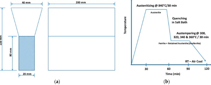
[image:4.595.84.507.374.402.2]With calculated charging materials, the molten metal was prepared in an induction type electric furnace. Ductile iron, in the form of Y-blocks, with the dimensions shown in the Figure1a, was cast. The section thickness of the Y-block with 20 mm was chosen based on the casting section thickness. The chemical composition was analyzed using a spark type optical emission spectrometer and is given in Table1.
Table 1.Chemistry of Spheroidal Graphite Iron.
Element C Si Mn S P Mg Cu Cr Mo Ni CE
Weight (%) 3.68 2.54 0.19 0.001 0.038 0.045 0.61 0.03 0.25 0.82 4.51
2.2. Austempering of Ductile Iron
The austempering heat treatment cycle is shown in Figure1b. After initial preheating for 10 min at 450◦C to remove oil/dirt from the sample surface in a preheating furnace, the samples were austenitized at 840◦C for 30 min in a sealed austempering furnace. The austenitizing temperature and time were selected from the preliminary experiments on the basis of the minimum level required to completely austenitize the entire specimen. Then, they were subjected to austempering, an isothermal heat treatment technique, in which samples were quenched in a molten salt bath of sodium and potassium nitrate salts. The transfer of samples from an elevated temperature to the quench tank was done within 5 s, to ensure an ausferritic structure. Austempering was done at 4 different temperatures: 300◦C, 320◦C, 340◦C and 360◦C, to study the effect of the austempering temperature on mechanical properties and microstructural evolution. These temperatures were chosen to avoid the formation of bainite and/or martensite at a lower austempering temperature. After austempering, the samples were fed into a hot water washing machine for 30 min to remove the salt on the surface of the samples.
[image:4.595.128.467.609.746.2]2.3. Mechanical Testing and Optical Microscopy
The hardness testing of as-cast and austempered samples was carried out using a Brinell Hardness Tester at a 3000 kg applied load, using a 10 mm diameter steel ball. The tensile testing was carried out in a semi-automated machine. Samples with a 70 mm gauge length (L) and 14 mm gauge diameter (D) were used in the machine. Samples were cut from the lower portion of Y-blocks and tested in the machine. The impact tests were conducted in a Charpy type impact tester. Samples were cut from the Y-blocks; then, the rectangular unnotched samples were tested in the machine, in cold working conditions, in dimensions of 55 mm×10 mm×10 mm, as per the specifications.
Samples for optical microscopic investigation were cut from the head of the tensile test samples. Samples were subjected to rough grinding, polishing, using different grades of emery papers and finally, fine polishing. Then the samples were etched using 2% Nital for a few seconds and microstructural evolutions were investigated using an optical microscopy, coupled with an image analyzer. The images were captured at a magnification of 100×before etching and 400×after etching. In all tests reported in Sections2.3–2.6, four tests were carried out and the mean value is reported.
2.4. Pin-on-Disc Wear Testing
The wear resistances of samples were evaluated using a pin-on-disc wear testing machine (DUCOM—TR-20LE-CHM-400, Bohemia, NY, USA). The wear disc of 155 mm diameter and 8 mm thickness was fabricated from EN31 grade steel, with a hardness of 60±2 on “C” scale of Rockwell Hardness. The ADI pin samples, with 30 mm length and 6 mm diameter, were tested in the machine. The wear test parameters were chosen as follows: load—50 N, and RPM—500, for a sliding distance of 1 km.
2.5. Scanning Electron Microscopy
For examination under electron microscopy, the samples, after metallographic preparation, were subjected to polishing for 2 min, washed with distilled water and ethanol, followed by 5 min ultrasonic agitation. The samples were stored in a vacuum chamber overnight to remove excess material and dust. Then, the specimens were put in the SEM chamber (SEC—SNE 3200M, SEC Co., Ltd., Suwon, South Korea) and final plasma cleaning was done for 10 min. The secondary electron images were done on etched samples, to investigate the surface morphology, using 30µm aperture at 20 kV and a working distance of 8–12 mm.
2.6. X-ray Diffraction Analysis
To quantify the phases present in the alloys, the samples were prepared for X-ray diffraction experiments in an X-Pert PRO PANalytical (Almelo, The Netherlands) goniometer. The samples were cut into small strips of 5 mm thickness and the surface was ground using SiC emery papers, to remove the surface contamination and to ensure flatness. Then, the whole thing was mounted on the specimen holder in the X-ray goniometer, using double sided tape. Specimens were examined with Cu–Kα
radiation at 30 kV and 10 mA with a step size of 0.02◦, 2 s per step, spot size of 5 mm×5 mm, start angle of 40◦and end angle of 50◦. Then, the results were analysed using the direct comparison method, to determine the volume fraction of retained austenite present in the matrix.
3. Results and Discussions
3.1. Microstructure
pearlitic grade of spheroidal graphite iron. As expected, the as-cast structure is like a “bull’s eye” in appearance, where dark graphite nodules were encircled by the white ferrite phase.
Figure 2.Microstructure of As-Cast Ductile Iron using Optical Microscopy at 100×.
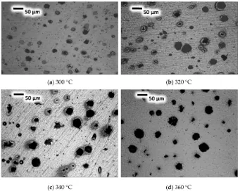
The microstructures, captured at four different austempering temperatures: 300◦C, 320◦C, 340◦C and 360◦C are shown in Figure3a–d, respectively.
Figure 3.Microstructures at Different Austempering Temperature (a) 300◦C, (b) 320◦C, (c) 340◦C and (d) 360◦C using Metallurgical Microscopy at 100×.
[image:6.595.127.468.365.641.2]Figure 4.Nodule Count and Graphite Content.
When austempered, the austenite forms at the grain boundary of ferrite and then grows into ferrite by the nucleation and growth processes. Thus, nucleation produces ferritic matrix containing thin layers of carbon-enriched austenite. Further, austenite continues to nucleate at prior ferrite grain boundaries. As austenite becomes enriched and saturated with carbon, difficulty is encountered in the diffusion of carbon ahead of ferrite. Hence the growth of ferrite is arrested. The microstructure of ADI mainly consists of mixture of carbon-stabilized austenite and acicular ferrite. This special product phase of austempering heat treatment is called “Ausferrite”. The dark needle-like structures are called acicular ferrite and white regions are called carbon-enriched austenite, as shown in Figure5. It is also observed that the microstructure becomes coarse with an increase in austempering temperature.
[image:7.595.116.482.431.726.2]3.2. Mechanical Properties
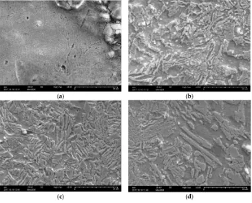
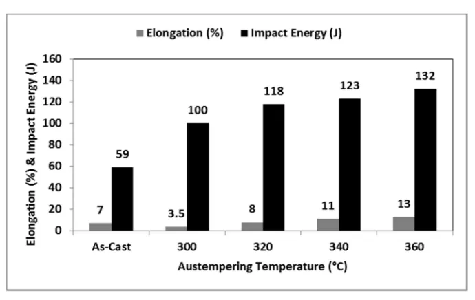
From the micrographs, it is evident that as the austempering temperature increases, from 300◦C to 360◦C, the microstructure becomes coarser. This could be due to the grain coarsening behavior at higher austempering temperatures and is reflected in the reduction of hardness and strength values, as shown in Figure6a,b respectively. It was also observed that the increase in austempering temperature increases the retained austenite content, which will directly improve the ductility and impact energy, as shown in Figure7.
[image:8.595.81.521.312.457.2]The hardness and strength values are higher at low austempering temperatures, which produces a lower ausferritic microstructure, which is ideal for improvements in hardness, strength, fatigue [31–33] and specific wear. This could be due to lesser development of carbon-enriched austenite. At an elevated austempering temperature, more carbon-stabilized austenite is formed, which results in increased ductility and impact toughness. This is attributed to the increased amount of carbon present in austenite. The increase in the austempering temperature results both in a greater amount of austenite stabilization and carbon enrichment, which is an ideal structure for improving ductility and impact energy.
Figure 6.(a) Hardness and (b) Strength.
[image:8.595.126.471.489.707.2]3.3. Effect on Retained Austenite
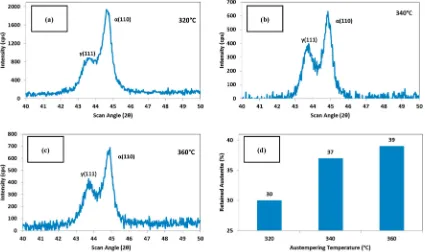
[image:9.595.85.510.165.417.2]The XRD profiles were analyzed using X-Pert PRO software, (Version 2.2) to find out the peak positions and the intensities of the {111} plane of austenite and {110} plane of ferrite. The ferrite and austenite contents were calculated using the intensities of the above planes and are shown in Figure8.
Figure 8.XRD pattern at (a) 320◦C, (b) 340◦C, (c) 360◦C and (d) Retained Austenite content .
The correlation between the austenite content and the austempering temperature is shown in Figure8d. It was observed that the retained austenite increases as the austempering temperature increases. At a lower austempering temperature (320◦C), no ausferrite forms—only retained austenite plus lower bainite is present—whereas at higher temperatures, as the ausferrite reaction occurs at the upper bainitic region, the matrix contains reacted austenite only.
3.4. Effect on Specific Wear
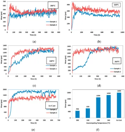
The wear resistances (in terms of specific wear) of as-cast and austempered samples at different temperatures are shown in Figure9f. The pin-on-disc test depicts the wear of a component that would have arisen after traversing a distance of nearly 1 km, and is plotted. The readings were read after a lapse of about 300 s, when a plateau was reached and that value was taken and plotted in Figure9f. From the figure, it is obvious that the wear increases with an increase in the austempering temperature. At lower austempering temperatures, wear loss is low, due to the fine lower ausferritic structure. At elevated austempering temperatures, wear loss is high, due to the presence of coarse upper ausferrite. The wear loss of as-cast samples is higher than austempered samples, because of the softer ferritic and pearlitic structure. There is a drastic decrease in wear resistance when the austempering temperature is changed from 320◦C to 340◦C, which could be due to the formation of a greater amount of retained austenite—which is a softer phase—at 340◦C when compared with 320◦C, as shown in Figure8d.
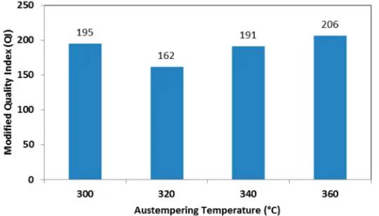
3.5. Quality Index
ADI is used in wear resistant applications, such as railways and impeller earth moving components, the quality index equation was modified by the current authors to include wear resistance, and is given below:
Modified Quality Index(QI) = (UTS in ksi)2∗(% Elongation1000+Normalised Wear Resistance) (1)
[image:10.595.92.501.235.664.2]The modified quality index has been chosen in such a way that it retains the contributions of ultimate tensile strength (UTS) and elongation to the same extent and includes the contribution of wear resistance. The use of the modified quality index will be a valuable tool in the selection of grades for components, to arrive at optimum combinations of properties.
Figure 9.Specific Wear at (a) 300◦C, (b) 320◦C, (c) 340◦C, (d) 360◦C, (e) As-Cast and (f) Plot of wear against austempering temperature.
The specimen austempered at 340◦C showed a better combination of tensile strength, elongation and wear resistance.
Figure 10.Modified Quality Index.
3.6. Energy Consumption
Since our study has shown that the required properties are achieved at a lower austenitizing temperature and time of 840◦C and 30 min, respectively as well as at a lower austempering temperature and time of 340◦C and 30 min, this gives about an 8% saving in energy consumption as compared to higher austempering times and higher austempering temperatures. This leads to less total energy cost and also less greenhouse gas emissions, thereby promoting green manufacturing. This energy investigation is only for one particular specific component in this industry and a detailed work is planned in the future.
4. Conclusions
• The as-cast structure of nodular iron mainly consists of pearlite and ferrite with the presence of dark graphite nodules encircled by white ferrite phase, appearing like a “bull’s eye”. Since the pearlite content is higher than the ferrite content, it is considered a pearlitic grade of spheroidal graphite iron. ADI microstructures of all samples austempered at 300–360◦C consist of acicular ferrite and carbon-enriched austenite, called “ausferrite”.
• The nodule count of ADI decreases and the nodule size increases with an increase in the austempering temperature.
• Decreases in hardness and strength were found when there was an increase in austempering temperature, from 300 to 360◦C. This could be due to the coarsening of the microstructure at elevated temperatures, which is observed in optical and scanning electron microscopic images.
• With an increase in austempering temperature from 300 to 360 ◦C, elongation as well as impact toughness gradually increases. This is because an increased amount of austenite is stabilized/enriched due to carbon dissolution at a higher temperature and the same is confirmed by XRD analysis.
• The increase in austempering temperature resulted in increased specific wear. The change in wear is very high between 320◦C and 340◦C.
• A modified quality index was envisaged, incorporating tensile strength, elongation and wear resistance and it will be useful for practicing engineers in selection of components higher the index, the better the strength as well as wear resistance properties. The samples austempered at 340◦C and 360◦C showed better values.
Acknowledgments:The authors acknowledge that the work described in this paper was funded by the Royal Academy of Engineering, London, under its Higher Education Partnership—India Newton Bhabha Scheme.
Author Contributions: Prabhukumar Sellamuthu worked as a Research Scholar in this project and helped in experiments. D. G. Harris Samuel and D. Dinakaran conceived, designed the experiments and led the research activities. V. P. Premkumar extended the expertise in arriving at the composition. Zushu Li and Sridhar Seetharaman contributed to analyzing the results and reviewed.
Conflicts of Interest:The authors declare no conflict of interest.
References
1. Tanaka, Y.; Kage, H. Development and Application of Austempered Spheroidal Graphite Cast Iron.
Mater. Trans.1992,33, 543–557. [CrossRef]
2. Mi, Y. Effect of Cu, Mo, Si on the Content of Retained Austenite of Austempered Ductile iron.Scr. Metall.
1995,32, 1313–1317. [CrossRef]
3. Eric, O.; Rajnovic, D.; Zec, S.; Sidjanin, L.; Jovanovic, M.T. Microstructure and fracture of alloyed austempered ductile iron.Mater. Charact.2006,57, 211–217. [CrossRef]
4. Franetovic, V.; Shea, M.M.; Ryntz, E.F. Transmission electron microscopy study of austempered nodular iron: Influence of silicon content, austenitizing time and austempering temperature. Mater. Sci. Eng.1987,96, 231–235. [CrossRef]
5. Panneerselvam, S.; Martis, C.J.; Putatunda, S.K.; Boileau, J.M. An investigation on the stability of austenite in austempered ductile cast iron (ADI).Mater. Sci. Eng. A2015,626, 237–246. [CrossRef]
6. Putatunda, S.K. Development of austempered ductile cast iron (ADI) with simultaneous high yield strength and fracture toughness by a novel two-step austempering process. Mater. Sci. Eng. A2001,315, 70–80. [CrossRef]
7. Zhang, N.; Zhang, J.; Lu, L.; Zhang, M.; Zeng, D.; Song, Q. Wear and friction behavior of austempered ductile iron as railway wheel material.Mater. Des.2016,89, 815–822. [CrossRef]
8. Hemanth, J. Effect of cooling rate on dendrite arm spacing (DAS), eutectic cell count (ECC) and ultimate tensile strength (UTS) of austempered chilled ductile iron.Mater. Des.1999,21, 1–8. [CrossRef]
9. Cast Metals Development Ltd. Austempered ductile-iron castings—Advantages, production, properties and specifications.Mater. Des.1992,13, 285–297.
10. Trudel, A.; Gagne, M. Effect of Composition and Heat Treatment Parameters on the Characteristics of Austempered Ductile Irons.Can. Metall. Q.1997,36, 289–298. [CrossRef]
11. Putatunda, S.K.; Gadicherla, P.K. Influence of austenitizing temperature on fracture toughness of a low manganese austempered ductile iron (ADI) with ferritic as cast structure.Mater. Sci. Eng. A1999,268, 15–31. [CrossRef]
12. Rao, P.P.; Putatunda, S.K. Investigations on the fracture toughness of austempered ductile irons austenitized at different temperatures.Mater. Sci. Eng. A2003,349, 136–149. [CrossRef]
13. Eric, O.; Jovanovic, M.; Sidjanin, L.; Rajnovic, D.; Zec, S. The austempering study of alloyed ductile iron.
Mater. Des.2006,27, 617–622. [CrossRef]
14. Sohi, M.H.; Ahmadabadi, M.N.; Vahdat, A.B. The role of austempering parameters on the structure and mechanical properties of heavy section ADI.J. Mater. Process. Technol.2004,153–154, 203–208. [CrossRef] 15. Hsu, C.H.; Shy, Y.H.; Yu, Y.H.; Lee, S.C. Effect of austempering heat treatment on fracture toughness of
copper alloyed gray iron.Mater. Chem. Phys.2000,63, 75–81. [CrossRef]
16. Kim, Y.J.; Shin, H.; Park, H.; Lim, J.D. Investigation into mechanical properties of austempered ductile cast iron (ADI) in accordance with austempering temperature.Mater. Lett.2008,62, 357–360. [CrossRef] 17. Guerra, L.F.V.; Jacuinde, A.B.; Mejia, I.; Zuno, J.; Maldonado, C. Effects of boron addition and austempering
time on microstructure, hardness, and tensile properties of ductile irons. Mater. Sci. Eng. A2015,648, 193–201. [CrossRef]
18. Dias, J.F.; Ribeiro, G.O.; Carmo, D.J.; Vilela, J.J. The effect of reducing the austempering time on the fatigue properties of austempered ductile iron.Mater. Sci. Eng. A2012,556, 408–413. [CrossRef]
20. Lu, G.X.; Zhang, H. Sliding wear characteristics of austempered ductile iron with and without laser hardening. Wear1990,138, 1–12.
21. Zhou, W.S.; Zhou, Q.D.; Meng, S.K. Lubricated sliding and rolling wear of austempered ductile iron.Wear
1993,162–164, 696–702. [CrossRef]
22. Ahmadabadi, M.N.; Ghasemi, H.M.; Osia, M. Effects of successive austempering on the tribological behaviour of ductile cast iron.Wear1999,231, 293–300. [CrossRef]
23. Haseeb, A.S.M.A.; Islam, M.A.; Bepari, M.M.A. Tribological behaviour of quenched and tempered, and austempered ductile iron at the same hardness level.Wear2000,244, 15–19. [CrossRef]
24. Ghaderi, A.R.; Ahmadabadi, M.N.; Ghasemi, H.M. Effect of graphite morphologies on the tribological behaviour of austempered cast iron.Wear2003,255, 410–416. [CrossRef]
25. Zimba, J.; Samandi, M.; Yu, D.; Chandra, T.; Navara, E.; Simbi, D.J. Un-lubricated sliding wear performance of unalloyed austempered ductile iron under high contact stresses.Mater. Des.2004,25, 431–438. [CrossRef] 26. Perez, M.J.; Cisneros, M.M.; Lopez, H.F. Wear resistance of Cu-Ni-Mo austempered ductile iron.Wear2006,
260, 879–885. [CrossRef]
27. Zhang, J.; Zhang, N.; Zhang, M.; Zeng, D.; Song, Q.; Lu, L. Rolling-sliding wear of austempered ductile iron with different strength grades.Wear2014,318, 62–67. [CrossRef]
28. Jacuinde, A.B.; Guerra, F.V.; Rainforth, M.; Mejia, I.; Maldonado, C. Sliding wear behavior of austempered ductile iron micro alloyed with boron.Wear2015,330–331, 23–31. [CrossRef]
29. Zammit, A.; Abela, S.; Wagner, L.; Mhaede, M.; Grech, M. Tribological behaviour of shot peened Cu-Ni austempered ductile iron.Wear2013,302, 829–836. [CrossRef]
30. Straffelini, G.; Giuliari, C.; Pelizzari, M.; Veneri, E.; Bronzato, M. Dry rolling-sliding wear of austempered cast iron.Wear2011,271, 1602–1608. [CrossRef]
31. Lin, C.K.; Lai, P.K.; Shih, T.S. Influence of microstructure on the fatigue properties of austempered ductile irons—I. High-cycle fatigue.Int. J. Fatigue1996,18, 297–307. [CrossRef]
32. Lin, C.K.; Hung, T.P. Influence of microstructure on the fatigue properties of austempered ductile irons—II. Low-cycle fatigue.Int. J. Fatigue1996,18, 309–320. [CrossRef]
33. Meneghetti, G.; Ricotta, M.; Masaggia, S.; Atzori, B. Comparison of the low-cycle and medium-cycle fatigue behaviour of ferritic, pearlitic, isothermed and austempered ductile irons.Fatigue Fract. Eng. Mater. Struct.
2013,36, 913–929. [CrossRef]
34. Fatahalla, N.; Hussein, O. Microstructure, mechanical properties, toughness, wear characteristics and fracture phenomena of austenitized and austempered low-alloyed ductile iron.Open Access Libr. J.2015,2, 1–16.