SPARC CPU-5V
Technical Reference Manual
Material Number: 203651
FORCE COMPUTERS IncJGmhH All Rights Reserved
This document shall not be duplicated, nor its contents used for any purpose, unless written permission has been granted.
Copyright by FORCE COMPUTERS®
NOTICE
The information in this document has been carefully checked and is believed to be entirely reliable. FORCE COMPUTERS makes no warranty of any kind with regard to the material in this document, and assumes no responsibility for any errors that may appear in this document. FORCE COMPUTERS reserves the right to make changes without notice to this, or any of its products, to improve reiiabiiity, perfor-mance or design.
FORCE COMPUTERS assumes no responsibility for the use of any circuitry other than circuitry which is part of a product of FORCE COMPUTERS GmbH/Inc.
FORCE COMPUTERS does not convey to the purchaser of the product described herein any license under the patent rights of FORCE COMPUTERS GmbH/Inc. nor the rights of others.
FORCE COMPUTERS Inc. 2001 Logic Drive
San Jose, CA 95124·3468 U.S.A.
Tel.: FAX:
(408) 369-6000 (408) 371-3382
FORCE COMPUTERS France S.A.R.L. Le Volta
17 -19 rue Jeanne Braconnier F-92366 Meudon La Foret Cede>: France
Tel.: FAX:
(1141 0795 15 (1) 45 37 06 19
FORCE COMPUTERS GmbH Prof.-Messerschmitt-Str.1 0-85579 NeubiberglMunich Germany
Tel.: FAX:
(089) 608 14-0 (089) 609 77 93
FORCE COMPUTERS U.K. Ltd. Alton House Office Park Gatehouse Way
Aylesbury, Bucks. HP19 3XU United Kingdom
Tel.: FAX:
cpu-sv
Technical Reference Manual Table of Contents Table 1. Table 2. Table 3. Table 4. Table 5. Table 6. Table 7. Table 8. Table 9. Table 10. Table II. Table 12. Table 13. Table 14. Table 15. Table 16. Table 17. Table 18. Table 19. Table 20. Table 21. Table 22. Table 23. Table 24. Table 25. Table 26. Table 27. Table 28. Table 29. Table 30. Table 31. Table 32. Table 33. Table 34. Table 35. Table 36. Table 37. Table 38. Table 39. Table 40. Table 41. Table 42.List of Tables
Specifications of the SPARC CPU-SV ... 4
Ordering Information ... 6
History of Manual.. .... .... ... ... .... ... ... ... ... ... ... ... .... 8
Default Switch Settings ... 12
Device Alias Definitions ... ... 22
Setting Configuration Parameters ... 23
Diagnostic Routines ... 25
Commands to Display System Inform.ation ... 29
Front Panel Layout... 33
SPARC CPU-SV Connectors ... 34
Ethernet Connector Pinout ... 35
Serial Port A and B Connector Pinout ... 36
SCSI 50-Pin Connector ... 38
KeyboardIMouse Connector Pinout... 40
VME P2 Connector Pinout .. _... ... 41
IOBP-I0 PI Pinout... 43
IOBP-10 P2 Pinout (SCSI) ... 45
IOBP-I0 P3 Pinout (Floppy) ... 46
IOBP-I0 P4 Pinout (Centronics) ... 47
IOBP-I0 P5 Pinout (Serial)... 48
IOBP-IO P6 Pinout (Ethernet) .~ ... 48
Physical Memory Map of microSP ARC-II... 54
Bank Selection ... 55
CPU-SV Memory Banks ... 56
MEM-5 Memory Banks ... 56
Physical Memory Map of SBus on SPARC CPu-SV ... 57
NCR89CI05 Chip Address Map ... 63
RS-232, RS-422 or RS-485 Configuration ... 64
Serial Ports A and B Pinout List (RS-232) ... 65
Switch Settings for Ports A and B (RS-232}... 65
Serial Ports A and B Pinout List (RS-422) ... ... 66
Switch Settings for Ports A and B (RS-422}... 67
Serial Ports A and B Pinout List (RS-485) ... 68
Switch Settings for Ports A and B (RS-485)... 68
8-Bit Local YO Devices ... 70
Boot Flash Memory Capacity ...•... ... ... 71
User Flash Memory Capacity ...•... 72
Physical Memory Map of VMEbus Interface on SP ARC cpu-sv ... 79
Front Panel Layout... ... ... ... .... ... ... .... ... 83
Interrupt Mapping. ... ... .... ... .... ... ... .... .... 109
V}dEbus Transaction TImer Timeout Values ... 153
Watchdog Timer TImeout Values ... 156
Cpu-sv Technical Reference Manual Table of Contents SECTIONl 1. 1.1. 1.2. 1.3. 1.3.1. 1.4. SECTION 2 2. 2.1. 2.2. 2.3. 2.3.I. 2.4. 2.4.1. 2.4.2. 2.4.2.1. 2.4.2.2. 2.4.3. 2.4.4. 2.4.5. 2.4.5.1. 2.4.5.2. 2.4.6. 2.4.7. 2.4.8. 2.4.9. 2.4.10. 2.5. 2.5.I. 2.5.2. 2.5.3. 2.5.4. 2.5.5. 2.5.6. 2.6. 2.6.1. 2.7. 2.7.I. 2.72. 2.7.3.
INTR.ODUCTION ... 1
Getting Startec:l ... _... ...•... •.•• ... . .... 1
The SPARe CPU-SV Technical Reference Manual Set ... 1
Summary of the SP ARC CPU-SV ... 2
Specifications ... 4
Ordering InfoIDlation ... 6
History of the Manual ... 8
INSTALLATION ... 9
In'trod.uction... I . . . 89
Caution ... 9
Location Diagram of the SP ARC CPU-SV Board ... 9
Before Powering Up ... 12
Default Switch Settings... 12
Powering Up ... ... ... ... ... ... ... 14
VME Slot-1
Device...
14VMEbus SYSRESEr EnablelDisable ... 15
SYSRESEr Input ... ... ... ... 15
SYSRESET Output ... 15
Serial Ports ... '" 15 RESET and ABORT Key Enable ... 16
SCSI Termination ...•... 16
SCSI Termination at the Front Panel... 16
SCSI Termination at P2 ... 16
Boot Flash Memory Write Protection... 17
User Flash Memory Write Protection ... 17
Reserved Switches ... ...•... ... 17
Parallel Port or Floppy Interface via VME P2 Connector ... 18
Ethernet via Front Panel or VME P2 Connector ... 19
OpenBoot Fimlware ...•... 20
Boot the System ...•... 20
NVRAM Boot Parameters ... 23
Diagnostics ... ... ... ... ... 24
Display System Information ...•... 28
Reset the System ... ... ... ... ... ... 30
OpenBoot Help .. ... ... ... 30
Front Panel ...•...•... 32
Features of the Front Panel ... 33
SPARC CPU-SV Connectors ... 34
Ethernet Connector Pinout ... 35
Serial Port A and B Connector Pinout ... 36
SCSI Connector Pinout ... 38
Table of Contents CPU-SV Technical Reference Manual
2.7.4. KeyboardlMouse Connector Pinout ... 40
2.7.5. ~ P2 Connector Pinout ... 41
2.7.6. The IOBP-I0 Connectors ... 42
2.8. SECTION 3 3. 3.l. 3.2. 3.2.l. 3.2.2. 3.3. 3.4. 3.5. 3.5.l. 3.6. 3.6.1. 3.6.2. 3.6.3. 3.6.4. 3.65. 3.7. 3.7.1. 3.7.2. 3.7.3. 3.7.4. 3.7.5. 3.7.6. 3.7.7. 3.7.8. 3.7.9. 3.7.10. 3.7.11. 3.7.12. 3.7.13. 3.7.13.1. 3.7.13.2. 3.7.13.3. How to Determine the Ethernet Address and Host ID ... 49
HA.RDW ARE. DESCRIPTION ... _ ... 51
Overview ________ • _ _ ._ ... _ _ _ _ _ _ _ _ _ _ 51 Block Diagram ... 51
The microSPARC-n Processor ... 53
Features of
me
microSPARC-II Processor ... 53Address Mapping formicroSPARC-n ... 54
The Shared Memory ... 55
Memory Module ~-5 ... 56
SBus Participants ...•... 57
Address Mapping for SBus Slots on the SPARC CPU-SV ... 57
NCR89Cl00 (MACIO) ... 58
Features of the NCR89Cl00 on the SP ARC CPU-SV ... 59
SCSI ... 60
SCSI Termination ... 60
Ethernet ... ... ... ... ... ... ... .... ... ... ... ... ... ... ... ... ... 61
Parallel Port ... 61
NCR89CI05 (SlA VIO) ... 62
Features of the NCR89CI05 on the SPARC CPU-SV ... 62
Address Map of Local I/O Devices on SP ARC CPU-SV ... 63
Serial I/O Ports... 64
RS-232, RS-422 or RS-485 Configuration ... 64
RS-232 Hardware Configuration ... 65
RS-422 Hardware Configuration ... 66
RS-485 Hardware Configuration ... 68
Keyboard and Mouse Port ... 69
Floppy Disk Interface ... ... 69
8-Bit Local I/O Devices ... 70
Boot Flash Memory ... 71
User Flash Memory ...•... 72
Programming the On-board Flash Memories ... 73
Flash Memory Programming Voltage Control Register ... 74
Flash Memory Programming Control Register 1 ... 75
cpu-sv
Technical Reference Manual Table of Contents 3.8.3.1. 3.8.3.2. 3.9. 3.10. 3.10.1. 3.10.1.1. 3.10.1.2. 3.10.2. 3.10.2.1. 3.10.2.2. 3.10.3. 3.10.3.1. 3.10.4. 3.10.4.1. 3.11. 3.11.1. 3.11.2. SECTION 4 4. 4.1. 4.2. 4.2.1. 4.2.2. 4.2.3. 4.2.4. 4.2.5. 4.2.6. 4.2.7. 4.2.8. 4.2.9. 4.2.10. 4.2.11. 4.2.12. 4.2.13. 4.2.14. 4.2.15. 4.2.16. 4.3. 4.3.1. 4.3.2. 4.3.3. 4.3.4.SYSRESET Input ... 81
SYSRESET Output ... ... 81
On-board Control Registers (System Configuration) ... 82
Front Panel ...•... 83
RESET and ABORT Keys ... 84
The RESET Key ... 84
The ABORT Key ... 84
Front Panel Status LEDs ... 85
USER LED 1 Control Register ... 86
USER LED 2 Control Register... 87
Diagnostic LED (Hex Display) ... 88
Seven Segment LED Display Control Register... 88
Rotary Switch... 89
Rotary Switch Status Register ... 89
Additional Registers ... 90
FMB Channel 0 Data Discard Status Register ... 90
FMB Channell Data Discard Status Register ... 90
OpenBoot ... 91
Sof'tw'are ••••••••• I ' • I . . . , . . " • • 1 . . . • • • • • • • • • • • • • • • • • • • • • • '1' I . . . 91
OpenB oot ...•...•...•...•...•... 91
VMEbus Interface ... 92
Generic Information ... ... ... .... 92
Register Addresses ... ... ... ... ... ... ... 93
Register Accesses ... 98
VMEbus Interrupt Handler ...•... ... 108
VMEbus Arbiter... 112
VMEbus Requester ... ... ... ... ... ... 113
VMEbus Status Signals... 115
V1\1Ebus Master Interface ... 117
V?ffibus Slave Interface ... 127
VMEbus Device Node ... 131
VMEbus NVRAM Configuration Parameters ... 133
DMA Controller Support ... 142
Mailboxes and Semaphores ... 146
FORCE Message Broadcast... 148
Diagnostic ... 151
Miscellanea ... 152
Standard Initialization of the VMEbus Interface ... 154
SP ARC FGA-5000 Registers... 154
VMEbus Transaction Timer ... 154
SBus Rerun Limit ... 154
Interrupts ... 154
Table of Contents CPU-sv Technical Reference Manual 4.3.5. 4.4. 4.4.1. 4.4.2. 4.4.3. 4.4.4. 4.4.5. 4.4.6. 4.5. 4.5.1. 4.5.2. 4.5.3. 4.5.4. 4.6. 4.6.1. 4.6.2. 4.6.3. 4.6.4. 4.65. SECTIONS 5. 5.1.
SBus Slot 5 Address Map ... 155
System Configuration ... 156
Watchdog Timer ... 156
Watchdog Timer NVRAM Configuration Parameters ... 158
Abort Switch ... 158
Abort Switch NVRAM Configuration Parameter ... 159
LEDs, Seven-Segment Display and Rotary Switch ... 159
Reset ...•... 160
Flash Memory Support ... 162
Flash Memory Programming ... 162
Flash Memory Device ... 164
Loading and Executing Programs from USER Flash Memory ... 166
Controlling the Flash Memory Interface... 167
Onboard Interrupts ... _... ... ... ... ... ... .... 169
~us Interrupts... 169
SYSF AII.. Interrupt ... ... ... ... ... ... ... ... ... .... .... .... 170
ACF AII.. Interrupt ... ... ... ... ... 171
ABORT Interrupt ... 172
Watchdog Timer Interrupt ... 172
CIRC'UIT SCHE.MA.TICS ... _ ... 175
CPU-SV Schematics ... . . ... _ _ _ .... . ... _._.175 MEM-5 Schematics ... 176
SECTION 6 SUN OPEN BOOT DOCUMENTATION ____ •• ___ ... _.177 6. Insert your OPEN BOOT 2.0 PROM MANUAL SET here. ... .. ... _177 SECTION 7 APPENDIX. ... 179
7. Product Error Report ... .. ... 179
SECTION 8 USER'S NOTES ... 181
Cpu-sv Technical Reference Manual Table of Contents
SECTION 10 MODWICATIONS ... 185 10. Additional ModificatioDS_... . .... ___ • ____ • _____ • __ • ______ ._. 185
SECTION 11 APPLICATIONS ... 187 11. Additional ApplicatioDS_, _ _ _ _ _ _ _ ._ ••• _ _ _ .. , _ _ _ _ _ _ _ .187
Table of Contents
cpu-sv
Technical Reference ManualFigure 1.
Figure 2.
Figure 3. Figure 4. Figure 5.
Figure 6.
Figure 7.
Figure 8.
Figure 9.
Figure 10. Figure 11.
Figure 12.
Figure 13.
List of Figures
Block Diagram of the SP ARC CPU-SV ... 3
Diagram of the CPU-SV (Top View) ... 10
Diagram of the CPU-SV (Bottom View) ... 11
Floppy Interface Via VME P2 Connector ... 18
Ethernet Interface via Front Panel ... 19
Diagram of the Front Panel ... 32
Pinout of the Ethernet Cable Connector ... 35
Serial Ports A and B Connector Pinout ... 37
Pinout of SCSI Connector ... 39
KeyboardIMouse Connector ___ ,_' ___ ... 40
The IOBP-l 0 ... 42
Block Diagram of the SP ARC CPU-SV ... 52
SPARC CPU-SV Technical Reference Manual Introduction
SECTIONl
INTRODUCTION
1.
Getting Started
This SPARe CPU-5V Technical Reference Manual provides a comprehensive guide to the SPARe CPU-5V board you purchased from FORCE COMPUTERS. In addition, each board delivered by FORCE includes an Installation Guide.
Please take a moment to examine the Table of Contents of the SPARC CPU-5V Technical Reference Manual to see how this documentation is structured. This will be of value to you when looking for infonnation in the future.
1.1
The
SPARe
CPU-SV Technical Reference Manual Set
When purchased from FORCE, this set includes the SPARC CPU-5V Technical Reference Manual as well as two additional books. These two books are listed here:
Set of Data Sheets for the SPARC CPU-SV
OPEN BOOT PROM 2.0 MANUAL SET
The Set of Data Sheets for the SPARC CPU-5V contains the following data sheets.
NCR SBus YO Chipset Data Manual
microSPARC-ll User's Manual (STPI012POA) SOS-THOMSON MK48T08(B)-10/12115/20
AMD Flash EPROM (AM2SF020) Intel Flash Memory (28FOOSSA-L)
The OPEN BOOT PROM 2.0 MANUAL SET contains the following three sections.
Open Boot 2.0 Quick Reference Open Boot 2.0 Command Reference,
FORCE COMPUTERS
FCODE Programs
Introduction SP ARC CPU-SV Technical Reference Manual
1.2
Summary
of the
SPARe
cpu-sv
The SPARC CPU-5V addresses embedded applications where processing performance is as important as VMEbus throughput. Based on FORCE COMPUTERS FGA-5000 VMEbus to SBus interface gate array, the SPARC CPU-5V provides high speed VMEbus transfer capabilities for standard transfers and extended 64-bit :MBLT transfers. In addition, the SPARC CPU-5V implements the capabilities of Sun Microsystems' SPARCstation 5 workstation on a single-slot VMEbus board.
The SPARC CPU-5V is powerd by the microSPARC-II processor, which delivers a sustained processing performance of 76 SPECint92 and 65 SPECfp92. The complete suite of I/O functions includes fast SCSI-2, Ethernet, floppy disk, serial 110, Centronics parallel ItO and keyboard/mouse ports making the SPARC CPU-5V the ideal solution for computing and VME transfer intensive embedded applications.
A complete 64-bit VMEbus interface and two standard SBus slots enable the expansion of 110 memory and processing performance with a broad range of off-the-shelf solutions. The software support for the SPARC CPU-SV ranges from Solaris, the most popular implementation of the UNIX operating system on a RISC architecture, to sophisticated real-time operating systems such as VxWorks.
SP ARC CPU-SV Technical Reference Manual Introduction
FIGUREl.
Block Diagram of the
SPARe cpu-sv
f7
Keyboard! RotaIy S1aIus Abort Resett?
BhemeI SCSJ.2 Serial 110 Mouse Swkh Display
\
\
t r - ! r - I
I J
~
l)
~ 16-Of'Sf..Wbyre
IMtrtcty &p.nsicn an.m.tSlA 1~\7I~
\ll
I
16-0f'~rl
BootI
IJ«nOI'y &p.nsianFlash IUtnoty I
NCR89Cf05 I I
NCR89C100.
I
16-«~
StllialVO.
H
zMBU-at.met SCSI. ~
CJD.boatrI DRAM
FIapf:1y.te.y- RahIMmtNy
c.no-c:s I
i - - ~
Y
I
I~
I
RTCINVFIAN mit:toSPARC-I1~ H~ I IUIFPUIIIMUI
MalrixJ Floppy
I
C«dIeseus I
L
FGA-SOOOditct
S8uH>VAIBU
I
SSusSlotI
l
SBusSSotJ
~
I
I
"W
VllEbu:rP2 VlleusP1Introduction SP ARC CPU-SV Technical Reference Manual
1.3
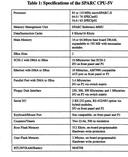
Specifications
[image:14.623.64.476.137.642.2]Below is a table outlining the specifications of the SP ARC CPU-5V board.
Table 1: Specifications of the
SPARe cpu-sv
Processor 85 or 110 MHz microSPARc-n
64.0/76 SPECint92
54.6/65 SPECfp92
Memory Management Unit SPARC Reference MMU
Data/lnstruction Cache 8 Kbytel16 Kbyte
Main Memory 16-0r 64-Mbyte base board DRAM,
expandable to 192 MB with mezzanine modules
SBus Slots 2
SCSI-2 with DMA to SBus 10 Mbyteslsec fast SCSI-2
110 on front panel and P2
Ethernet with DMA to SBus 10 Mbitslsec, AM7990 compatible AU! port on front panel or P2 Parallel Port with DMA to SBus 3,4 Mbytes/sec
110 on P2 via switch matrix
Floppy Disk Interface 250, 300, 500 Kbyteslsec and 1 Mbytelsec
110 on P2 via switch matrix
Serial 110 2 RS-232 ports, RS-4221485 option via
hybrid modules,
110 on front panel and P2
KeyboardIMouse Port Sun compatible, on front panel and P2
CountersITtmers Two 22-bit, SOO ns resolution
Boot Flash Memory 512 Kbyte, on-board programmable
Hardware write protection
User Flash Memory 2 Mbytes, on-board programmable
Hardware write protection
SPARC CPU-SV Technical Reference Manual Introduction
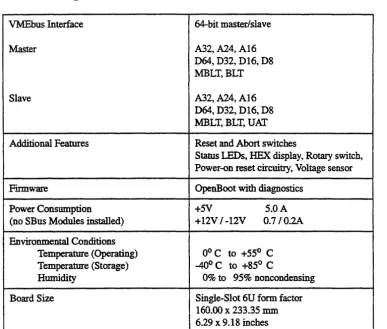
Table 1: Specifications of the SPARC CPU-SV (Continued)
VMEbus Interface
Master
Slave
Additional Features
Firmware
Power Consumption (no SBus Modules installed)
Environmental Conditions Temperature (Operating) Temperature (Storage)
Humidity
Board Size
FORCE COMPUTERS
64-bit master/slave
A32, A24, A16 064, D32, D16, D8 MBLT,BLT
A32, A24, A16 D64, D32, D16, D8 MBLT, BLT, UAT Reset and Abort switches
Status LEDs, HEX display, Rotary switch, Power-on reset circuitry, Voltage sensor OpenBoot with diagnostics
+5V 5.0 A
+12V /-12V 0.7/0.2A
Ooc to +550 C
-400 C to +850 C
0% to 95% noncondensing Single-Slot 6U form factor 160.00 x 233.35 nun
6.29 x 9.18 inches
Introduction SPARC CPU-5V Technic31 Reference Manual
1.3.1
Ordering Information
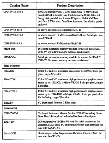
[image:16.615.79.497.162.709.2]This next page contains a list of the product names and their descriptions.
Table 2: Ordering Information
Catalog Name Product Description
CPU-SV/16-110-2 110 MHz microSPARc-n CPU board with 16-Mbyte base board DRAM, 2-Mbyte User Flash Memory, SCSI, Ethernet, floppy disk, parallel and 2 serial I/O ports, 64-bit VMEbus interface, 2 SBus slots, OpenBoot firmware. Installation guide included.
CPU-SVI16-85-2 as above, except 85 MHz microSPARC-n.
CPU-SV 164-110-2 as above, except 110 MHz microSPARC-ll and 64-Mbyte base I board DRAM.
CPU-SV/64-85-2 as above, except 85 MHz microSPARC-n.
:MEM-5/16 16-Mbyte mezzanine memory module for use on the SPARC CPU-sv. Up to two memory modules can be used.
MEM-5/64 64-Mbyte mezzanine memory module for use on the SPARC CPU-SV. Up to two memory modules can be used.
SBus Modules
SBuslGX Color 2-D and 3-D wireframe accelerator 1152x900, 8 bits per pixel, single SBus slot.
SBustrGX Color 2-D and 3-D wireframe high performance graphics accel-erator up to 1152x900, I-Mbyte VRAM, 8 bits per pixel, single SBus slot.
SBustrGX+ Color 2-D and 3-D wireframe high performance graphics accel-erator up to 16OOx1280, 4-Mbyte VRAM, 8 bits per pixel, dou- -ble buffering, single SB us slot.
SBusIFP 6U front panel for up to 2 SBus cards.
Accessories
CPU-SVIfM Technical Reference Manual Set for CPU-SV including
SPARC CPU-SV Technical Reference Manual Introduction
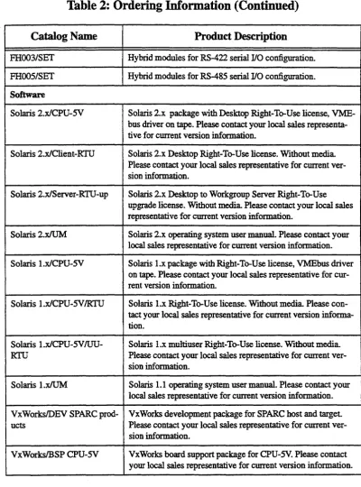
Table 2: Ordering Information (Continued)
Catalog Name Product Description
FHOO3/SET Hybrid modules for RS-422 serial I/O configuration. FHOO51SET Hybrid modules for RS-485 serial I/O configuration. Software
Solaris 2.xlCPU-5V Solaris 2.x package with Desktop Right-To-Use license, VME-bus driver on tape. Please contact your local sales representa-tive for current version information.
Solaris 2.xlClient-RTU Solaris 2.x Desktop Right-To-Use license. Without media Please contact your local sales representative for current ver-sion information.
Solaris 2.xlServer-RTU-up Solaris 2.x Desktop to Workgroup Server Right-To-Use upgrade license. Without media Please contact your local sales representative for current version information.
Solaris 2.xIUM Solaris 2.x operating system user manual. Please contact your local sales representative for current version information. Solaris l.xlCPU-5V Solaris l.x package with Right-To-Use license, VMEbus driver
on tape. Please contact your local sales representative for cur-rent version information.
Solaris I.xlCPU-5V!RTU Solaris l.x Right-To-Use license. Without media Please con-tact your local sales representative for current version informa-tion.
Solaris l.xlCPU-5V IUU- Solaris l.x multiuser Right-To-Use license. Without media
RTU Please contact your local sales representative for current ver-sion information.
Solaris I.xIUM Solaris 1.1 operating system user manual. Please contact your local sales representative for current version information. VxWorksIDEV SPARC prod- VxWorks development package for SPARC host and target. ucts Please contact your local sales representative for current
ver-sion information.
VxWorksIBSP CPU-5V VxWorks board support package for CPU-5V. Please contact your local sales representative for current version information.
Introduction SPARC CPU-SV Technical Reference Manual
1.4
ffistory of
the
Manual
Below is a description of the publication history of this SPARC CPU-5V Technical Reference Manual.
Table 3:
History
of Manual
Revision No. Description Date
SPARC CPU-SV Installation
SECTION 2
INSTALLATION
2.
Introduction
This Installation Section provides guidelines for powering up the SP ARC CPU-5V board. The Installation Section, which you have in your hand now, appears both as Section 2 of the SP ARC CPU-5V Technical Reference Manual and as a stand-alone Installation Guide. This stand-alone Installation Guide is delivered by FORCE COMPUTERS with every board. The SP ARC CPU-5V Technical Reference Manual provides a comprehensive hardware and software guide to your board and is intended for those persons who require complete information.
2.1
Caution
Please read this Installation Section before installing the board. Take a moment to examine the Table of Contents to see how this documentation is structured. This will be of value to you when looking for specific information in the future.
2.2
Location Diagram of the
SPARe
CPU-SV Board
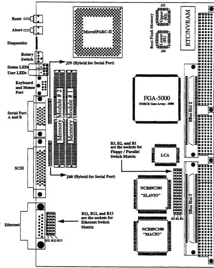
A location diagram showing the important components on the top side of the CPU-5V appears on the next page. On the page next to it, there is a location diagram showing the bottom side of the CPU-5V. Both of these diagrams show only the components on the board which are of interest to the user.
IDstalIation
FIGURE 2.
Diagram of the CPU-SV (Top View)
Serial Port AandB
SCSI
. ' Ethernet
..:.:.:.:.:.:.:.:.:.:.:.:.:.:.:.:
•••••••••••••••••••••••••••••••••
~.~...
~,.-:.:.:
:.:.:.
:.:.:.
.:.:.:
••••••
•••
• :.:.:MicroSPARC.fi :::::::.:.:.
.:.:.:
••••••
•
•••••
• !.!.. • ...••••••
••••••
•••••••••••••••••••••••••••••••••
.
:.:
•••••••••••••••••••••••••••••
.••..•••.•.••••.•...•••...•..
_.Y:!:~ .. r-~JS9 (Hybrid for Serial Port):: I·
4.
-:
.
••
•
••
•
••
• I "e
BUBllB13FGA-5000 FORCE Cdte Arnt!. 5800
B3t B2, and Bl
are the sockets for Floppy I Parallel Switch Matrix
SPARC CPU-SV
FIGURE 3.
Diagram of the CPU-SV (Bottom View)
Switch 8
LCA CoIIfig.
Rc:scnaI Slot IFIICt.
CII3b1cd
PoM:rSeasc 4.514.7SV
WriII:User RranI:d
~
SW6 SW8
••
Switch 5
0
0
SWS~o~
•
°coo
00°0 Switch 4
°coo
•
°coo
°000
0000 SW4
FORCE COMPUTERS
SW7
•
Switch 7RESETSW eDabIcd ABORI'SW eDabIcd SYSltESET 1Naab1cd SYSRESET our eab1ed
Installation SPARC CPU-SV
2.3
Before Powering Up
Before powering up, please make sure that the default switch settings are all set according to the table below. Check these switch settings before powering up the SPARe CPU-5V because the board is configured for power up according to these default settings. For the position of the switches on the board, please see "Diagram of the CPU-5V (Top View)" on page 10.
2.3.1
Default Switch Settings
Table 4: Default Switch Settings
Diagram of Switch
with Default Setting Switches
Default
Setting Function
SWITCH 4 (Serial A Configuration)
SWITCH SWS (Controls Serial Channel
B)
SWS-1 ON On
=
SER..TRXCB to TXC_B_CONN (Pin 25) Off=
SER_RrS_B to TXC_B_CONN (Pin 25)SWS
SWS-2 OFF On=
crS_B_CONN (Pin 13) to SER_RIXCB andOn Pullup Off
=
RTXC-.B_CONN (Pin 22) to SER_RTXCB and to SER_CI'SB crs_B_CONN (Pin 13) to ~crsBSPARe cpu-sv Installation
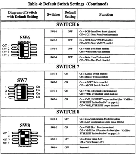
Table 4: Default Switch Settings (Continued)
Diagram of Switch with Default Setting
SW6
Off 1
Off 2
Off 3
Off 4
SW7
l-...IfI!~
2
3 4
Off 1
2
003
Off 4
SW8
FORCE CO:MPUTERS On On On On OnSwitches Default Setting
SWITCH 6
SW6-1 OFF SW6-2 OFF SW6-3 OFF SW6-4 OFF
SWITCH 7
SW7-1 ON SW7-2 ON SW7-3 ON SW7-4 ON
SWITCH 8
SW8-1 OFF SWS-2 ON
SW8-3 OFF SWS-4 OFF
Function
On
=
SCSI-Tenn Front Panel disabled Off=
SCSI-Tenn Front Panel automatic On=
SCSI-Tenn VME P2 disabled Off=
SCSI-Tenn VME P2 enabled On=
Write Boot Flash enabledOff
=
Write Boot Flash disabled On=
Write User Flash enabled Off=
Write User Flash disabledOn = RESET Switch enabled Off
=
RESET Switch disabled On = ABORT Switch enabledOff = ABORI' Switch disabled On
=
VME_SYSRESET input enabled Off=
VME_SYSRESET input disabledOn = VME_SYSRESET output enabled (See "VMEbus SYSRESET &ableJDisable" on page 15)
Off = VME_SYSRESET output disabled
On = LCA Configuration Mode Download
Off = LCA Configuration Mode Serial PROM On = VME Slot 1 Function enabled
Off = VME Slot 1 Function disabled (See "VMEbus SYSRESET EnableJDisable" on page 15)
On
=
Power Sense 4.SVOff = Power Sense 4.7SV Reserved
Installation SPARC CPU-SV
2.4
Powering Up
The initial power up can easily be done by connecting a teoninal to ttya (serial port A). The advantage of using a teoninal is that no frame buffer, monitor, or keyboard is used for initial power up, which facilitates a simple start up.
Please see the chapter "OpenBoot Firmware" on page 20 for more detailed information on booting the system.
2.4.1
Vl.\IJE Slot-l
JJevice
The SP ARC CPU-5V can be plugged into any VMEbus slot; however, the default configuration sets the board as a VME slot-l device, which functions as VME system controller. To configure your CPU-5V in order that it is not a VME slot-1 device, the default configuration must be changed so that SW8-2 is OFF. In that case, it would also be necessary to change the SW7-4 to OFF, so that the VME_SYSRESET output is disabled.
CAUTION
SPARC CPU-SV Installation
2.4.2
VMEbus SYSRESET EnableIDisable
2.4.2.1
SYSRESET Input
An external SYSRESET generates an on-board RESET in the default switch setting, i.e., SW7-3 is ON. When SW7 -SW7-3 is OFF, the external SYSRESET does not generate an on-board RESET.
2.4.2.2
SYSRESET Output
An on-board RESET drives the SYSRESET signal to the VMEbus to low in the default switch setting, i.e., SW7-4 is ON. When SW7-4 is OFF, an on-board RESET doesn't drive the SYSRESET signal to the VMEbus to low.
CAUTION
Do not switch SW7 -4 (SYSRESET output) to ON and SW8-2 (VMEbus Slot-1 device) to OFF
at the same time.
The VMEbus Specification requires that if SYSRESET is driven, the SYSRESET signal shall be driven low for at least 200 IDS. However, when the CPU-5V is not a VMEbus slot-1 device
and the SYSRESET output signal is enabled, then the CPU-5V no longer conforms with this rule.
By default, the SYSRESET output is enabled. In this case it generates the SYSRESET signal to the VMEbus.
2.4.3
Serial Ports
By default, both serial ports are configured as RS-232 interfaces. It is also possible to configure both ports as RS-422 or RS-485 interfaces. This optional configuration is achieved with the special FORCE Hybrids FH-003 and FH-005.
The chapter ''Default Switch Settings" on page 12 shows the necessary switch settings for RS-232 operation, where SW4 controls serial port A and SW5 controls serial port B. Please check that the switches are set accordingly.
IDstaDation SPARC CPU-SV
2.4.4
RESET and ABORT
Key
Enable
To enable the RESET and the ABORT functions on the front panel, set switches SW7-1 (RESET) and SW7-2 (ABORT) to ON.
2.4.5
SCSI Termination
2.4.5.1
SCSI Termination at the Front Panel
Tennination at the front panel for the SCSI interface is automatic when SW6-1 is OFF. This is the default setting. Automatic means that when a SCSI cable is plugged into the front panel connector, the tennination is automatically disabled. When there is no SCSI cable plugged into the front panel, then the tennination is automatically enabled.
2.4.5.2
SCSI TennUmtion atP2
Tennination at the V1v.IEbus P2 for the SCSI interface is enabled when SW6-2 is OFF. This is the default setting.
CAUTION
SPARe CPU-SV Installation
2.4.6
Boot Flash Memory Write Protection
Both of the Boot Flash Memory devices are write protectable via the switch SW6-3. When SW6-3 is OFF, the devices are write protected.
2.4.7
User Flash
Memory Write Protection
The User Flash Memory devices are write protectable via SW6-4. When SW6-4 is OFF, the User Flash Memory devices are write protected.
2.4.8
Reserved Switches
SW 4-4, SW5-4, and SW8-4 are reserved for test purposes.
Installation SPARC CPU-SV
2.4.9
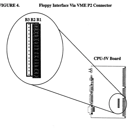
Parallel Port or Floppy Interface via VME P2 Connector
Via a 16-pin configuration switch matrix, it is possible for either the parallel port interface or the floppy interface to be available on the VME P2 connector.
The default setting enables the floppy interface via the VME P2 connector, with the configuration switch matrix plugged into Bland B2. This means, of course, that by default the parallel port interface is not available via the VMEbus P2 connector.
To enable the parallel port interface via the VME P2 connector, plug the configuration switch
[image:28.612.69.495.263.708.2]_ _ ...! __ ! _ _ _ _ 1._",_ '0'" __ .l '0'-' lll(1U.lA. III ~u\';l\.~~ D~ C11.lU DJ.
FIGURE 4.
Floppy Interface Via VME P2 Connector
SPARC CPU-SV Installation
2.4.10
Ethernet via Front Panel or VME P2 Connector
Via an 8-pin configuration switch matrix, it is either possible for the Ethernet interface to be available via the front panel or the VME P2 connector. The default configuration provides the Ethernet through the front panel connector.
In order to have the Ethernet interface accessible via the VME P2 connector, the default configuration must be changed.
By default, the Ethernet interface is available through the front panel with the configuration switch matrix plugged into connectors B12 and B13.
To configure the Ethernet interface to be accessible from the VMEbus P2 connector, the configuration switch matrix must be plugged into connectors B 11 and B 12.
FIGURES.
Ethernet Interface via Front Panel
BIIB12BI3
Cpu-sv
Board
I
WARNING: When the Ethernet interface is configured via VMEbus P2, do not connect the Ethernet at the front paneL
Installation SPARe cpu-sv
2.5
OpeuBoot Firmware
This chapter describes the use of OpenBoot fIrmware. Specifically, you will read how to perform the following tasks.
• Boot the System • Run Diagnostics
• Display System Information • Reset the System
• OpenBoot Help
For detailed information concerning OpenBoot, please see the OPEN BOOT PROM 2.0 MANUAL SET. This manual is included in the SPARC CPU-5V Technical Reference Manual
Set.
2.5.1
Boot the
System
The most important function of OpenBoot ftmlware is booting the system. Booting is the process of loading and executing a stand-alone program such as the operating system. After it is powered on, the system usually boots automatically after it has passed the Power On Selffest (POST). This occurs without user intervention.
If necessary, you can explicitly initiate the boot process from the OpenBoot command interpreter. Automatic booting uses the default boot device specified in non-volatile RAM (NVRAM); user initiated booting uses either the default boot device or one specified by the user.
To boot the system from the default boot device, type the following command at the Forth Monitor prompt.
I
ok bootSPARe cpu-sv InstaI1ation
The boot command has the following format:
boot [device-specifier] [ftlename] [-ah]
The optional parameters are described as follows.
[device-specifier]
[filename]
[-a] [-h]
The name (full path or alias) of the boot device. Typical values are cdrom, disk, floppy, net or tape.
The name of the program to be booted filename is relative to the root of the selected device. If no filename is specified, the boot command uses the value of boot-file NVRAM parameter. The NVRAM parameters used for booting are described in the following chapter.
-a prompt interactively for the device and name of the boot file.
-h halt after loading the program.
NOTE: These options are specific to the operating system and may differ from system to system.
To explicitly boot from the internal disk, type:
I
ok boot diskor at the Restricted Monitor prompt:
I
>bdiskInstallation SPARC CPU-SV
[image:32.623.75.495.130.388.2]To retrieve a list of all device alias definitions, type devalias at the Forth Monitor command prompt. The following table lists some typical device aliases:
Table 5: Device Alias Definitions
AIias Boot Path Description
disk liommu/sbuslespdmalesp/sd@3,0 Default disk (1st internal) SCSI-ID 3 disk3 lionunuisbuslespdmalesp/sd@3,0 First internal disk SCSI-ID 3
disk2 liommuisbuslespdmalespJsd@~O Additional internal disk SCSI-ID 2 disk 1 liommulsbuslespdmalesp/sd@ 1,0 External disk SCSI-ID 1
diskO liommuisbuslespdmalesplsd@O,O External disk SCSI-ID
°
tape liommuisbuslespdmalesp/st@4,0 First tape drive SCSI-ID 4 tapeO liommuisbuslespdmalesp/st@4,0 First tape drive SCSI-ID 4
tape 1 liommuisbuslespdmalesp/st@5,0 Second tape drive SCSI-ID 5
cdrom liommuisbuslespdma/esplsd@6,O:d CD-ROM partition d, SCSI-ID 6
net liommulsbuslledmalle Ethernet
SPARC CPU-SV Installation
2.5.2
NVRAM Boot Parameters
The OpenBoot fmnware holds configuration parameters in NVRAM. At the Forth Monitor prompt, type printenv to see a list of all available configuration parameters. The OpenBoot command setenv may be used to set these parameters.
setenv [configuration parameter] [value]
This information refers only to those configuration parameters which are involved in the boot process. The following table lists these parameters.
Table
6: Setting
Configuration
Parameters
Parameter Default Value Description
auto-boot? true If true, boot automatically after power on or reset boot-device disk Device from which to boot
boot-file empty sning FIle to boot
diag-switch? false If true, nm in diagnostic mode
diag-device net Device from which to boot in diagnostic mode diag-file empty sning File to boot in diagnostic mode
When booting an operating system or another stand-alone program, and neither a boot device nor a fllename is supplied, the boot command of the Forth Monitor takes the omitted values from the NVRAM configuration parameters. If the parameter diag-switch? is false, boot-device and boot-file are used. Otherwise, the OpenBoot fmnware uses diag-device and diag-flle for booting.
For a detailed description of all NVRAM configuration parameters, please refer to the OPEN BOOT PROM 2.0 MANUAL SET.
Installation SPARC CPU-SV
2.5.3
Diagnostics
At power on or after reset, the OpenBoot firmware executes POST. If the NVRAM configuration parameter diag-switch? is true for each test, a message is displayed on a tenninal connected to the first serial port. In case the system is not working correctly, error messages indicating the problem are displayed. After POST, the OpenBoot firmware boots an operating system or enters the Forth Monitor if the NVRAM configuration parameter auto-boot? is false.
The Forth Monitor includes several diagnostic routines. These on-board tests let you check devices such as network controller, SCSI devices, floppy disk system, memory, clock and installed SBus cards. User installed devices can be tested if their ftrmware includes a seiftest routine.
SPARC CPU-SV Installation
Table 7: Diagnostic Routines
Command Description
probe-scsi Identify devices connected to the on-board SCSI bus
probe-scsi-all [device-path] Perform probe-scsi on all SCSI buses installed in the system below the specified device tree node. (If
device-path is omitted, the root node is used.)
test device-specifier Execute the specified device's selftest method. device-specifier may be a device path name or a device alias.
For example:
test net -test network connection
test Imemory -test number of megabytes specified in
the selftest-#megs NVRAM parameter or test all of memory if diag-switch? is true
test-all [device-specifier] Test all devices (that have a built-in selftest method) below the specified device tree node. (If device-path is omitted, the root node is used.)
watch-clock Monitor the clock function
watch-net Monitor network connection
To check the on-board SCSI bus for connected devices, type:
ok probe-sc:si
Target 3
Unit 0 Disk MICROP 1684-07MB l036511ASOC1684 ok
To test all the SCSI buses installed in the system, type:
ok probe-scsi-all
liommu@O,lOOOOOOO/sbus@O,lOOOl000/esp@2,lOOOOO Target 6
Unit 0 Disk Removable Read Only Device SONY CD-ROM CDU-8012 3.1a
liommu@O, 1 OOOOOOO/sbus@O, 1 0001 OOO/espdma@4,8400000/esp@4,8800000
Target 3
Unit 0 Disk MICROP 1684-07MB 1036511ASOC1684
ok
The actual response depends on the devices on the SCSI buses.
IDstaJlation SPARC CPU-SV
To test a single installed device, type:
I
ok test device-specifierThis executes the device method name selftest of the specified device node.
device-specifier may be a device path name or a device alias as described in Table 5, ''Device Alias Defmitions," on page 22.The response depends on the selftest of the device node.
To test a group of installed devices, type:
I
ok test-aDAll devices below the root node of the device tree are tested. The response depends on the devices that have a selftest routine. If a device specifier option is supplied at the command line, all devices below the specified device tree node are tested.
When you use the memory testing routine, the system tests the number of megabytes of memory specified in the NVRAM configuration parameter selfiest-#megs. If the NVRAM configuration parameter diag-switch? is true, all memory is tested.
I ok_imemOIy
:ling
32 megs of memory at addr 0 TI
The command test-memory is equivalent to testlmemory. In the example above, the frrst number (0) is the base address of the memory bank to be tested, the second number (27) is the number of megabytes remaining. If the CPU board is working correctly, the memory is erased and tested and you will receive the ok prompt. If the PROM or the on-board memory is not working, you receive one of a number of possible error messages indicating the problem.
To test the clock function, type:
ok watcb-dock
Watching the 'seconds' register of the real time clock chip. It should be 'ticking' once a second.
Type any key to stop.
SPARC CPU-SV
To monitor the network connection, type:
ok watch-net
Using AUI Ethernet Interface Lance register test - succeeded. lnternalloopback test -- succeeded. Externalloopback test -- succeeded. Looking for Ethernet packets.
, .' is a good packet. 'X' is a bad packet.
Type any key to stop .
... .x ... .x ... .
ok
Installation
The system monitors the network traffic, displaying"." each time it receives a valid packet and displaying "X" each time it receives a packet with an error that can be detected by the network hardware interface.
Installation SPARC CPU-SV
2.5.4
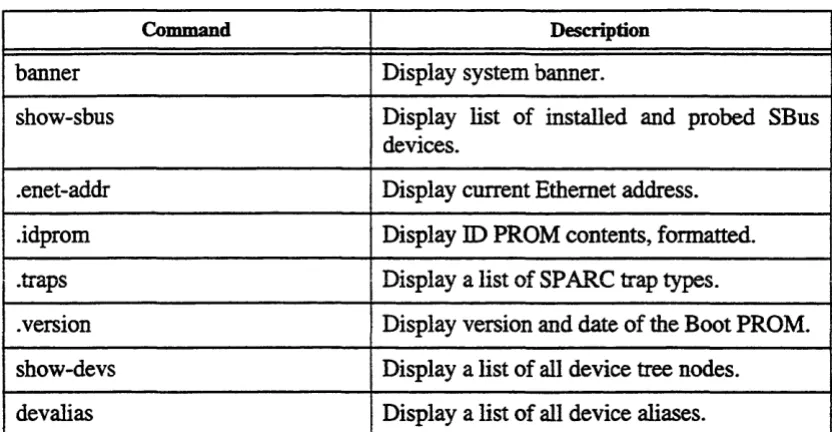
Display System Information
The Forth Monitor provides several commands to display system information. These commands let you display the system banner, the Ethernet address for the Ethernet controller, the contents of the ID PROM, and the version number of the OpenBoot fIrmware.
The ID PROM contains information specifIc to each individual machine, including the serial number, date of manufacture, and assigned Ethernet address.
SPARC CPU-SV Installation
Table 8: Commands to Display System Information
Command Description
banner Display system banner.
show-sbus Display list of installed and probed SBus devices .
. enet-addr Display current Ethernet address .
.idprom Display ID PROM contents, formatted.
. traps Display a list of SP ARC trap types .
. version Display version and date of the Boot PROM . show-devs Display a list of all device tree nodes.
devalias Display a list of all device aliases.
Installation SPARe cpu-sv
2.5.5
Reset the System
If your system needs to be reset, you either press the reset button on the front panel or, if you are in the Forth Monitor, type reset on the command line.
I
ok resetThe system immediately begins executing the Power On Selffest (pOST) and initialization procedures. Once the POST finishes, the system either boots automatically or enters the Forth IvIonitor, just as it would have done after a power-on cycle.
2.5.6
OpenBoot Help
The Forth Monitor contains an on-line help. To get this, type:
ok help
Enter 'help command-name' or 'help category-name' for more help (Use ONLY the first word of a category description)
Examples: help select -or- help line Main categories are:
File download and boot Resume execution Diag (diagnostic routines) Power on reset
>-prompt Floppy eject Select YO devices Ethernet
System and boot configuration parameters Line editor
Tools (memory~numbers,new commands,loops)
Assembly debugging (breakpoints,registers,disassembly,symbolic) Sync (synchronize disk data)
Nvramrc (making new commands permanent)
ok
SPARe cpu-sv
An example of how to get help for special forth words or subcategories:
ok help tools
Category: Tools (memory,numbers,new commands,loops) Sub-categories are:
Memory access Arithmetic
Radix (number base conversions) Numeric output
Defining new commands Repeated loops
ok
ok help memory
Category: Memory access
dump ( addr length - ) display memory at addr for length bytes fill ( addr length byte - ) fill memory starting at addr with byte move ( src dest length - ) copy length bytes from src to dest address map? ( vaddr -- ) show memory map information for the virtual address I? ( addr - ) display the 32-bit number from location addr
w? ( addr - ) display the 16-bit number from location addr c? ( addr - ) display the 8-bit number from location addr l@ (add! - n ) place on the stack the 32-bit data at location addr w@ ( addr - n ) place on the stack the 16-bit data at location addr c@ (addr - n ) place on the stack the 8-bit data at location addr
l! ( n addr -- ) store the 32-bit value n at location addr w! ( n addr - ) store the 16-bit value n at location addr
c! (n addr - ) store the 8-bit value n at location addr
ok
Installation
The on-line help shows you the forth word, the parameter stack before and after execution of the forth word (before - after), and a short description.
The on-line help of the Forth Monitor is located in the boot PROM, so there is not an online help for all forth words.
IDstaIIation SPARe cpu-sv
2.6
Front Panel
FIGURE 6.
Diagram of the Front Panel
r=1
t...=:J
@ RESET
" ABORT , . "
[8]!
[@]g
E
mRUNBM
[]Ol
~K
~g
S
E R
I
A
L
A
+
B
s c S
I
E
T H E R
N
SPARC CPU-SV Installation
2.6.1
Features of the Front Panel
[image:43.623.121.509.172.408.2]The features listed below are described in detail in Section 3 of the SP ARC CPU-5V Technical Reference Manual.
Table 9: Front Panel Layout
Device Function Name
Switch Reset RESET
Switch Abort ABORT
HEX. Display Diagnostic DIAG
Rotary Switch User defined MODE
LEDlLED RUNIHALT RUN
VME BusmasterlSYSFAlL BM
LEDILED Software prognmunable 01
Mini DIN Connector KeyboardIMouse KBD
Serial Connector Serial Interfaces SERIALA+B
SCSI Connector SCSI Interface SCSI
D-Sub Connector Ethemet ETHERNET
Installation SPARC CPU·SV
2.7
SPARC CPU-5V Connectors
[image:44.612.94.479.144.380.2]The connectors on the SPARC CPU-5V are listed in the following table.
Table 10: SPARe CPU-SV Connectors
I
Manufacturer Part NumberAMP 747&45-4
~--.---- r--- - - -- -- - ----
-Serial Pon A + B 'Front Panel 26-pin Fine Pitch AMP 749831-2 SCSI Front Panel 5O-pin Fme Pitch AMP 749831-5 KeyboardIMouse FrontPaDeI 8-pin MiDi DIN AMP 749232-1
SBus SI0t2 P3 96-pinSMD FUJITSU FCN-234J096-GN (SBus Slave Select 1)
SBusSI0t3 P4 96-pinSMD FUJITSU FCN-234J096-GN (SBus Slave Select 2)
VMEbusPl PI 96-pinVGA Various
VMEbusP2 P2 96-pinVGA Various
SPARe cpu-sv InstaUation
2.7.1
Ethernet Connector Pinout
The following table is a pinout of the Ethernet connector. The figure below shows the Ethernet connector and pin numbers.
FIGURE'.
[image:45.620.214.419.174.499.2]FORCE COMPUTERS
Table 11: Ethernet Connector Pinout
Pin Function
1 AnalogGND
2 Collision+ 3 Transmit Data+ 4 AnalogGND
5 Receive Data+ 6 AnalogGND 7 N.C. 8 AnalogGND 9
Conision-10 Transmit Data-11 AnalogGND
12 Receive
Data-13 +12VDC
14 AnalogGND
15 N.C.
Pinout of the Ethernet Cable Connector
•
•••••••
15 • • • • • • • 9
Installation
SPARe cpu-sv
2.7.2
Serial Port A and B Connector Pinout
The following table is a pinout of the serial port connector. The figure on the next page shows the serial port connector and location of the pin numbers.
Table 12: Serial Port A and B Connector Pinout
Port
t
DescriptionNot connected
1 none none A
- -- --
---2 TD output A Transmit Data
3 RD input A Receive Data
4 RTS output A Request To Send
5 crs input A Clear To Send
6 DSR input A Data Set Ready
7 SG none A Signal Ground
8 DCD input A Data Carrier Detect
9 none none Not connected
10 none none Not connected
11 SDTR output B Secondary Data Terminal Ready 12 SDCD input B Secondary Data Camer Detect 13 scrs input B Secondary Clear To Send 14 STD output B Secondary Tnmsmit Data
15 TC input A Transmit Clock: DCE source
16 SRD input B Secondary Receive Data
17 RC input A Receive Clock
18 STC input B Secondary Transmit Clock 19 SRTS output B Secondary Request To Send 20 DTR output A Data Terminal Ready
SPARC CPU-SV
FIGURES.
FORCE COMPUTERS
Serial Ports A and B Connector Pinout
1
•••••••••••••
26··· 14
Installation
Installation SPARC CPU-SV
2.7.3
SCSI Connector Pinout
[image:48.618.151.412.159.686.2]The following table is a pinout of the SCSI connector. The figure on the next page shows the SCSI connector and location of the pin numbers.
Table 13: SCSI SO-Pin Connector
Pin No. Signal Pin No.
-
_
....-
-'" ~~.l~ClLGV2 GND 27 SCSI Data 1 3 GND 28 SCSI Data 2 4 GND 29 SCSI Data 3
5 GND 30 SCSI Data 4 6 GND 31 SCSI Data 5
7 GND 32 SCSI Data 6 8 GND 33 SCSI Data 7 9 GND 34 SCSIDP
10 GND 35 GND
11 GND 36 DISABLE
TERM
12 N.C. 37 N.C.
13 N.C. 38 TERMPWR 14 N.C. 39 N.C.
15 GND 40 GND
16 GND 41 SCSIATN
17 GND 42 GND
18 GND 43 SCSIBSY 19 GND 44 SCSIACK
SPARC CPU-SV Installation
FIGURE 9.
Pinout of SCSI Connector
• • • • • • • • • • • • • • • • • • • • • • • • •
1
···26
Installation SPARC CPU-SV
2.7.4
KeyboardIMouse Connector Pinout
The following table is a pinout of the keyboard/mouse connector. The keyboard and mouse port is available on the front panel via a Mini DIN connector.
Table 14: KeyboardIMouse Connector Pinout
Pin l?nn.-tinn
... A&& ....
---,,-..
1 GND
2 GND
3 +SVDC
4 Mouse In 5 Keyboard Out 6 Keyboard In 7 Mouse Out
8 +SVDC
SPARC CPU-SV Installation
2.7.5
VME P2 Connector Pinout
[image:51.613.130.497.147.692.2]The following table is a pinout of the V1v.IE P2 connector.
Table 15: VME P2 Connector Pinout
RowC RowC
PIN
Row A (Floppy drive available via (parallel Port available via switch matrix connected switch matrix connected to to sockets Bl & B2) sockets B2 & B3)1 SCSI Data 0 FLPYDENSEL CENTRDS 2 SCSI Data 1 FLPY DENSENSE CENTRDO
3 SCSI Data 2 CENTRDI CENTRDI
4 SCSI Data 3 FLPYINDEX CENTRD2 5 SCSI Data 4 FLPYDRVSEL CENTRD3
6 SCSI Data 5 CENTRD4 CENTRD4
7 SCSI Data 6 CENTRD5 CENTRD5
8 SCSI Dati 7 FLPYMOTEN CENTRD6
9 SCSIDP FLPYDIR CENTRD7
10 GND FLPYSTEP CENTRACK
11 GND FLPYWRDATA CENTRBSY
12 GND FLPYWRGATE CENTRPE
13 TERMPWR FLPYTRACKO CENTR~
14 GND FLPYWRPROT CENTRINIT
15 GND FLPYRDDATA CENTRERR
16 SCSIA1N FLPY HEADSEL CENTSLCTIN
17 GND FLPY DISKCHG CENTRSLCI'
18 SCSIBSY FLPYEJECT N.C.
19 SCSIACK ETH+12V ETH+12V
20 SCSIRST GND GND
21 SCSIMSG GND GND
22 SCSISEL ETHREC+"') ETH REC+:l) 23 SCSI CD ETHREC.:l) ETH REC·:l) . 24 SCSlREQ ETHTRA+:lJ ETHTRA+"'J 25 SCSI 10 ETHTRA.:l) ETHTRA.:l) 26 Mouse IN ETHCOL+:l) ETHCOL+:l) 27 Keyboard OUT ETHCOL-:l) ETHCOL-"')
28 Keyboard IN GND GND
29 TXDPortA TXDPortB TXDPOItB
30 RXDPortA RXDPortB RXDPoItB
31 RTSPOItA RTS PortB RTS PortB 32 CTSPortA ers PortB ers PortB
Installation SPARe cpu-sv
2.7.6
The IOBP-IO Connectors
[image:52.612.162.409.259.484.2]The 10BP-I 0 is an 110 back panel on VMEbus P2 with flat cable connectors for SCSI, serial 110, Centronics/floppy interface, and a micro D-Sub connector for an Ethernet interface. This back panel can be plugged into the VMEbus P2 connector. The diagram below shows all the connectors. This 10BP-IO back panel is especially designed for the SPARC CPU-5V. Do not use any other 110 back panels on the SPARC CPU-5V, for example, the IOBP-l.
FIGURE 11.
The IOBP·I0
P5 P3 P4
P2
.!!S 1 1 1 1 11 1
1 ~ > > 1 1
)
13 14 AlllID/SERIAL
i§=3
33 34P6 FL£FPY 39 40
~IO~
CENTRlMCSf49 so SCSI
The pinouts of the connectors (P I) ... (P6) are shown in the following tables.
CAUTION
SPARe cpu·sv Installation
Table 16: IOBP-I0 PI Pinout
ROW ROW ROW Signal for Signal for
A Signal
B
Signal C Floppy Parallel PortInterface 1 Interface 1
1 SCSI Data 0 1 N.C. 1 FPYDENSEL CENTRDS 2 SCSI Data 1 2 GND 2 FPYDENSENS CENTR Data 0 3 SCSI Data 2 3 N.C .. 3 N.C. CENTRData1 4 SCSI Data 3 4 N.C. 4 FPYINDEX CENTR Data 2 5 SCSI Data 4 5 N.C. 5 FPYDRVSEL CENTRData3 6 SCSI Data 5 6 N.C. 6 N.C. CENTRData4 7 SCSI Data 6 7 N.C. 7 N.C. CENTRData5 8 SCSI Data 7 8 N.C. 8 FPYMOTEN CENTRData6
9 SCSIDP 9 N.C. 9 FPYDm CENTRData7
10 GND 10 N.C. 10 FPYSTEP CENTRACK
11 GND 11 N.C. 11 FPYWRDATA CENTRBSY
12 GND 12 GND 12 FPYWRGATE CENTRPE
13 TERMPWR 13 N.C. 13 FPYTRACKO CENTRAF 14 GND 14 N.C. 14 FPYWRPROT CENTRINIT 15 GND 15 N.C. 15 FPYRDDATA CENTRERR 16 SCSIATN 16 N.C. 16 FPYHEADSEL CENTR SLCf IN 17 GND 17 N.C. 17 FPYDISKCHG CENTRSLCf 18 SCSIBSY 18 N.C. 18 FPYEJECT RESERVED
19 SCSIACK 19 N.C. 19 +12VOC 2 +12VDC 2
20 SCSIRST 20 N.C. 20 GND GND
21 SCSIMSG 21 N.C. 21 GND GND
22 SCSISEL 22 GND 22 ETHREC+ 2 EfHREC+ 2
23 SCSI CD 23 N.C. 23 ETHREC- 2 EfHREC- 2 24 SCSlREQ 24 N.C. 24 ETHTRA+2 EfHTRA+2 25 SCSI 10 25 N.C. 25 ETHTRA_2 ETHTRA_2 26 Mouse IN 26 N.C. 26 ETHCOL+ 2 ETHCOL+ 2
Installation SPARC CPU-SV
Table 16: IOBP-IO PI Pinout (Continued)
I
ROWI
Signal ROW Signal ROW Signal for Floppy Parallel Port Signal forA B
C
Interface 1 Interface 1 27 Keyboard 27 N.C. 27 EffiCOL-2 ETIICOL_2
Out
28 Keyboard In 28 N.C. 28 GND GND
29 TxDPortA 29 N.C. 29 TxDPortB TxDPortB
30 RxDPortA 30 N.C. 30 RxDPortB RxDPortB
31 RTS PortA 31 GND 31 RTS PortB RrS PortB
32 CTSPortA 32 N.C. 32 crsPortB CTSPortB
1) For further information, see ''Floppy Interface Via VME P2 Connector" on page 18
SPARCCPU-SV Installation
Table 17: IOBP-IO P2 Pinout (SCSI)
Pin
Signal Pin Signal
No.
No.
1 GND 2 SCSI Data 0
3 GND 4 SCSI Data 1
5 GND 6 SCSI Data 2
7 GND 8 SCSI Data 3
9 GND 10 SCSI Data 4
11 GND 12 SCSI Data 5
13 GND 14 SCSI Data 6
15 GND 16 SCSI Data 7
17 GND 18 SCSIDP
19 GND 20 GND
21 GND 22 GND
23 GND 24 GND
25 GND 26 TERMPWR
27 N.C. 28 GND
29 GND 30 GND
31 GND 32 SCSIA1N
33 GND 34 GND
35 GND 36 SCSIBSY
37 GND 38 SCSIACK
39 GND 40 SCSIRST
41 GND 42 SCSIMSG
43 GND 44 SCSISEL
45 GND 46 SCSI CD
47 GND 48 SCSIREQ
49 GND 50 SCSI 10
Installation SPARC CPU-SV
Table 18: IOBP-IO P3 Pinout (Floppy)
Pin
Signal Signal
No.
No.
1 FPYEJECT 2 FPYDENSEL
3 GND 4 FPYDENSENS
5 GND 6 N.C.
7 GND 8 FPYINDEX
9 GND 10 FPYDRVSEL
11 GND 12 N.C.
13 GND 14 N.C.
15 GND 16 FPYMOTEN
17 GND 18 FPYDIR
19 GND 20 FPYSTEP
21 GND 22 FPYWRDATA
23 GND 24 FPYWRGATE
25 GND 26 FPYTRACKO
27 N.C. 28 FPYWRPROT
29 GND 30 FPYRDDATA
31 GND 32 FPYHEADSEL
SPARe cpu-sv Installation
Table 19: IOBP-IO P4 Pinout (Centronics)
Pin
Signal Pin Signal
No. No.
1 CENTRDS 2 GND
3 CENTRDataO 4 GND
5 CENTRDatal 6 GND
7 CENTRData2 8 GND
9 CENTR Data 3 10 GND 11 CENTRData4 12 GND 13 CENTRData5 14 GND 15 CENTRData6 16 GND 17 CENTR Data 7 18 GND
19 CENTRACK 20 GND
21 CENTRBSY 22 GND
23 CENTRPE 24 GND
25 CENTRSLCT 26 CENTRINIT
27 CENTRAF 28 CENTRERR
29 N.C. 30 GND
31 GND 32 N.C.
33 N.C. 34 N.C.
35 N.C. 36 CENTR SLCT IN
37 N.C. 38 N.C.
39 N.C. 40 N.C.
Installation SPARe cpu-sv
Table 20: IOBP-IO P5 Pinout (Serial)
Pin
Signal Pin Signal
No.
No.
1 GND 2 Keyboard In
3 Mouse In 4 Keyboard Out 5 TxDPortB 6 TxDPortA
7 RxDPortB 8 RxDPortA
9 RTS PortB 10 RI'S PortA
11
crs
PortB 12 crsPortA13 GND 14 GND
Table 21: IOBP-IO P6 Pinout (Ethernet)
Pin Function
1
GND
2 Collision+ 3 Transmit Data+
4
GND
5 Receive Data+
6
GND
7 N.C.
8 N.C.
9 Collision-10 Transmit
[image:58.612.51.538.74.720.2]SPARC CPU-SV Installation
2.8
How to Determine the Ethernet Address and Host ID
This information explains how an Ethernet number and a host ID number are determined on a CPU-5V board.
Bytes
47
The 48-Bit (Six Byte) Ethernet Address
5 4 3 2 1
o
I
y yI
40 39 32 7 o
31 24 23f21
S16
15 8~ ______ +-______ ~ Mm~r ____ ~--~
The value of these three bytes always remains 008042 (HEX)
FORCE Inc. = 01 FORCE GmbH = 00
Specific Machine
(HEX)
The Ethernet Address
These two bytes contain the
rightmost four digits of the board's serial number in its hexadecimal representation
The Ethernet Address consists of a 48-bit (6-byte) number. The value of the most significant 24 bits is always 008042 (HEX). The value of the least significant 24 bits is calculated as follows.
The bits 23 and 22 identify whether the product is designed by FORCE COMPUTERS GmbH or by FORCE COMPUTERS Inc. The value is 00 for GmbH products and the value is 01 for Inc. products.
The bits 21 through 16 (least significant six bits of the third byte) identify a specific machine. The value of a CPU-5V board is 11 (decimal). Thus, the value of the most significant 32 bits (most significant four bytes) of a CPU-5V board from GmbH is 0080420B.
The least significant 16 bits (least significant two bytes) contain the rightmost four digits of the board's serial number in its hexadecimal representation.
Sample Serial HUmber : 2910 (decimal)
=
> OBSE (hexadectmal) Sample Ethernet Address: 00 80 42 OS OS SE (hexadecimal)Installation SPARC CPU-SV
The Host ID Number
The host ID is a 32-bit (4-byte) number and the eight most significant bits identify the architecture of the machine. The value representing the architecture of CPU-5V is 80 (HEX). The least significant 24 bits (least significant three bytes) contain the rightmost four digits of the board's serial number in its hexadecimal representation and the value 8B7000 (HEX) must be added to the converted serial number.
The Host ID Number
Bytes 3
~
32 • 25 These 8 bits identify architectme type
2
~
24
I
16o
~
7
I
0The least significant 24 bits contain the rightmost four digits of the board's serial number in its hexadecimal representation and the value 8B7000 most be added to the converted number.
Sample Serial Bamber: 2910 (decimal)
=->
OBSE (hexadecimal)Sample Bost :ID:
80 8B 7000
+ OBSE
SPARe CPU-SV Technical Reference Manual Hardware Description
SECTION 3
HARDWARE DESCRIPTION
3.
Overview
Based on FORCE COMPUTERS FGA-5000 VMEbus to SBus interface gate array, the SPARC CPU-5V provides high speed VMEbus transfer capabilities for standard transfers and extended 64-bit MBLT transfers. In addition, the SPARC CPU-5V implements the capabilities of Sun Microsystems' SPARCstation 5 workstation on a single-slot VMEbus board.
The SPARC CPU-5V is powered by the microSPARC-II processor, which delivers a sustained processing performance of 76 SPECint92 and 65 SPECfp92. The complete suite of JJO functions includes fast SCSI-2, Ethernet, floppy disk, serial I/O, Centronics parallel IlO and keyboard/mouse ports making the SPARe CPU-5V the ideal solution for computing and VME transfer intensive embedded applications.
A complete 64-bit VMEbus interface and two standard SBus slots enable the expansion of I/O memory and processing performance with a broad range of off-the-shelf solutions. The software support for the SPARC CPU-5V ranges from Solaris, the most popular implementation of the UNIX operating system on a RISC architecture, to sophisticated real-time operating systems such as VxWorks.
The SPARC CPU-5V is a single board computer combining workstation performance and functionality with the ruggedness and expandability of an industry-standard single-slot 6U VMEbus board.
3.1
Block Diagram
A block diagram showing a functional overview of the CPU-5V is shown on the next page.
Hardware Description SPARC
cpu-sv
Technical Reference ManualFIGURE 12.
Block Diagram of the
SPARe cpu-sv
)J
~ RoIary SIaIus AboIt R-.ett?
Ethernet SCSI-2 SeIIaIIfO Mouse Swtch Display\
\
..---, .r---1 r - . I I
~
~
-
1601'tullbya"-"Y~
IaVI1 VI Ett..tSlA
I
I
1601'tullbyar-1
BootI
"-"Y~Fi.ASH ii&iOiff
NCR I1!JC105 I I
NCRI9C1OD.
I
1601'tu _ _s.;.J1iO.
H211B1br
~~ ~ 0rt«Iard DRAM
Floppy. K#y- RASH M9«)RY
c.nInnics
~ ~
y
I
I~
I
RTCINIIRAMmictoSPARC-II ~
H=
I RYFPUIIIMUIFloppy
I
Cat:MI SSus I
L
~ahd
I SSusSlat I SSusSlDt
.5'BuN>o*E64
I
...
I