warwick.ac.uk/lib-publications
Original citation:Liang, Cunman, Wang, Fujun, Tian, Yanling, Zhao, Xingyu and Zhang, Dawei. (2017) Development of a high speed and precision wire clamp with both position and force regulations. Robotics and Computer-Integrated Manufacturing, 44. pp. 208-217.
Permanent WRAP URL:
http://wrap.warwick.ac.uk/94028
Copyright and reuse:
The Warwick Research Archive Portal (WRAP) makes this work by researchers of the University of Warwick available open access under the following conditions. Copyright © and all moral rights to the version of the paper presented here belong to the individual author(s) and/or other copyright owners. To the extent reasonable and practicable the material made available in WRAP has been checked for eligibility before being made available.
Copies of full items can be used for personal research or study, educational, or not-for-profit purposes without prior permission or charge. Provided that the authors, title and full bibliographic details are credited, a hyperlink and/or URL is given for the original metadata page and the content is not changed in any way.
Publisher’s statement:
© 2017, Elsevier. Licensed under the Creative Commons Attribution-NonCommercial-NoDerivatives 4.0 International http://creativecommons.org/licenses/by-nc-nd/4.0/ A note on versions:
The version presented here may differ from the published version or, version of record, if you wish to cite this item you are advised to consult the publisher’s version. Please see the ‘permanent WRAP URL’ above for details on accessing the published version and note that access may require a subscription.
Development of ahigh speed and precisionwire clamp with
both position and force regulations
Cunman Liang,Fujun Wang*, Yanling Tian, Xingyu Zhao, and Dawei Zhang
Key Laboratory of Mechanism Theory and Equipment Design of Ministry of Education, School of
Mechanical Engineering, Tianjin University, Tianjin300072, China
Abstract: This paper presents the mechanism and robust control of a monolithic wire
clamp to achieve fast and precision operations for strong androbustmicro device
packaging. The wire clamp is piezoelectrically actuated and a two-stage flexure-based
amplification was designed to obtain largeandparallel jaw displacements. The grasping
forces of the wire clamp were evaluated based on finite element analysis (FEA), and the
force measurement was presented. The wire clamp was manufactured using wire EDM
technique and the position and force transfer functions were obtained based on the
frequency response approach. The position/force switching control strategy was
employed to regulate the motion position and grasping force, and the position/force
switching controller composed of a PID controller for position control and a sliding
model controller (SMC) for force control was designed. Experimental tests were carried
out to investigate the performance of wire clamp with the position/force switching
controllerduring the grasping and releasing operations. The results show that the wire
clamp exhibits good performance and demonstrate that high speed and precision grasping
operations can be realized through the developed wire clamp and the control strategy.
Keywords: Wire clamp, flexure mechanism, mechanical design, position/force regulation
*Corresponding author: Fujun Wang, Key Laboratory of Mechanism Theory and Equipment Design
of Ministry of Education, School of Mechanical Engineering, Tianjin University, Tianjin 300072,
2
1. INTRODUCTION
Recently with the rapid development of microelectronic industries, the demand for
electronic products with high pin-count IC installations and high assembly density has
been increasingly growing[1-3]. As an important cost-effective and flexible
interconnecting technology for microdevice packaging, thermosonic wire bondinghas
been widely used for themicroelectronic packaging of nearly any type of daily used
electronic products [4]. Automatic wire bonders are important equipments for wire
bonding, and high performance wire bondersare required to produce smaller pad size and
finer pitch of microelectronic products in extreme conditions[5, 6]
As an important component of automatic wire bonders, wire clamps perform
high-frequency open and close operations during wire bonding process, and thus the
characteristics of wire clamps can directly affect the packaging quality and efficiency .
[7] .
During the extreme motion with short strokes and high acceleration[8, 9]
In the literature, there are some research reported on the wire clamps, most of which
mainly focused on the wire clamp actuators and mechanisms, and little attention has been
paid to their position/force control issues. The presently used wire clamps usually adopt
electromagnetic and piezoelectric actuators as drivers, and they can realize position
tracking using position feedback control. However, few of them have a real-time grasping
force controller
, there will be
some undesired disturbances to the wire and wire clamps, affecting the motion of the
clamps, which willfurther have influence on the bonding quality. As a result, it is
necessary to develop high performance wire clamps with a novel mechanism and robust
controller to provide stable and high speed microelectronic wire bonding.
[10, 11]
3
grasping force control was mainly carried out in indirect ways, such as through the
installation of preload springs or force calibration, making it difficult to achieve real time
and precision force control. However, the robust position/force control is of great
importance for the wire clamps to achieve robust and precision grasping and releasing
operations.
The position/force control has been receiving considerable attention from the
researchers. Impedance control strategy can be used to indirectly regulate the force using
a single controller through establishing the dynamic relation between the force and
position or velocity. However, the environmental conditions of wire clamps for
thermosonic wire bonding are not always certain, which makes it difficult to accurately
control the force using the indirectly control approach [12, 13]. Through hybrid
position/force control scheme, the grasping and releasing operations can be implemented
by controlling the position of the clamp jaws and monitoring the contact forces at the
same time, but the control performance largely depends on the division of force and
position subspaces, which requires to accurately identify the environmental constrains [14].
To overcome this issue, intelligent control methodologies, such as fuzzy and neural
network control, have been proposed to control forces [15, 16]
Intuitively, a position/force switching control can be used to regulate the grasping
jaw position and contact force alternately
. However, the calculation
amount becomes larger and the practical implementation process becomes more
complicated. Hence, a simple yet efficient approach is desirable to realize the stable and
precision force/position control of wire clamps.
[17, 18]
. As for the control scheme,
4
applications. However, traditional PID control can not accomplish the wire clamp
position/force regulation, because there may be high-frequency dynamic force vibrations
when the jaw contacts with the object during the fast grasping and releasing operations.
Some advanced control theories including the robust control [19], adaptive control [20],
iterative learning control [21] and neural networks control[22], were presented to control
precision positioning systems, which show appropriate level of performance. However,
their applications are limited in the fast and precision wire clamp control because of the
computationally expensive calculations [23]. Sliding mode control has the advantages of
fast response and strong robustness for the disturbances, and thus exhibits great potential
for the control of high-speed precision wire clamps [24]
This paper presents the mechanism and robust position/force switching control of a
novel monolithic piezoelectric actuated wire clamp. Firstly, the mechanism of the wire
clamp is introduced. The grasping force is investigated based on finite element analysis
(FEA), and the grasping force measurement is presented. The dynamic models of position
and force are obtained through frequency response approach, based on which the
position/force switching controller, composed of a PID position controller and a sliding
model force controller, is designed. The wire clamp is fabricated, and experimental tests
are carried out to investigate the performance of the wire clamp and controller. .
2. MECHANISM ANDGRASPING FORCE INVESTIGATION
2.1Configuration of the wire clamp
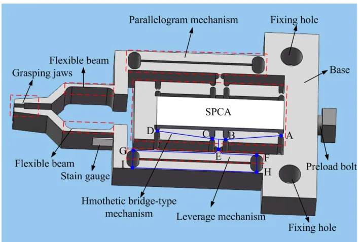
Figure 1 shows the mechanical structure of the piezoelectric actuated flexure-based
wire clamp consisting of a stack piezoelectric ceramic actuator (SPCA), a pair of
5
transmission mechanism designed as a two-stage amplification including a homothetic
bridge type mechanism and a parallelogram leverage mechanism. The SPCA is connected
with the flexible motion transmission mechanism by the preload bolt at one end of the
SPCA, and the preload force to the SPCA can be adjusted by the bolt. Both of the
grasping jaws connected with the motion transmission mechanism through two flexible
beams, and because of the space limit,
Through the two-stage amplification, the motion transmission and displacement
amplification from the SPCA to the grasping jaws are realized. As the first-stage
amplification the homothetic bridge-type mechanism is composed of a connecting rod
mechanism (A-B-C-D) based on double-notch circular flexure hinges, and its working
principle is that once actuated with an input displacement, the device produces two
vertical output displacements towards the SPCA. In order to obtain a large displacement
amplification ratio, a leverage mechanism (E-F-G) integrated within a parallelogram
mechanism (F-G-H-I) at each side of the wire clamp is designed as the second-stage
amplification connected with the homothetic bridge-type mechanism by two flexure
hinges. Through the parallelogram mechanism pure jaw translations can be realized, thus
avoiding the sliding between the wire and jaws during the operations, and more stable a stain gauge is adopted and surface bonded on the
left flexible beam to measure the grasping force during the grasping and releasing
operations. In order to avoid shear force and bending torque acting on the actuator, the
wire clamp is designed symmetrically along the longitudinal axis of the SPCA. Due to the
symmetric architecture, the measurement of a single flexible beam is sufficient. A stain
gauge is glued on the base end of the flexible beam where is the maximum stress point
6
and firm wire grasping can be ensured due to the fact that the grasping force will act
normal to the wirecompared with the angular grasping mode.
In order to grasp a wire, a voltage should be applied to the SPCA to make it expand
and push the homothetic bridge-type mechanism (A-B-C-D); then the homothetic
bridge-type mechanism will pull the leverage mechanisms (E-F-G-H-I), which causes the
grasping jaws to close to grasp the manipulated wire. After power is switched off, the
SPCA retracts to its initial position, causing the grasping jaws to open and release the
[image:7.612.129.483.317.556.2]manipulated wire.
Fig. 1 The mechanism of the wire clamp.
2.2Kinematic analysis of the wire clamp
There are various approaches to model a compliant mechanism, such as the
7
(FE) method[27]
2 / 3
2
1 ϕ ϕ π
ϕ i i
CD i
BC i
ABe l e l e se
l + + =
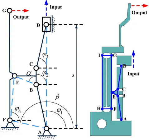
etc.PRB method is utilized to analyze the kinematic characteristics of the
wire clamp.Due to the symmetric architecture,onlyhalf of the wire clamp is considered
and the kinematic modelis established as shown in Fig 2, where i (i =A, B... J) denotes
the rotational centers of flexure hinges. From Fig. 2 it is can be seen that A-B-C-D-E-F is
equivalent to a six-bar linkage mechanismwith one degree of freedom. Based on the
geometric and motion relationships the following equations can be get:
(1)
4 2
1 (ϕ α) β ϕ
ϕ i
EF i AF i
BE i
ABe l e l e l e
l + + = + (2)
where s is the distance between the flexure hinges A and D, αis the angle between the
linkages BC andBE,β is the angle between linkage AFand the x-axis positive direction,
lj(j=AB, BC,..., AF) is the length of the linkage j, φ1, φ2, φ3 and φ4 are the initial angular
[image:8.612.186.425.442.666.2]positions of the linkages AB, BC, CD and FE, respectively.
8
DifferentiateEqs (1) and (2) with respect to time and let the real and imaginary parts
be equal. The following equation can be obtained:
s
B
Aω= (3)
where − + − + = 4 2 1 4 2 1 3 2 1 3 2 1 cos 0 ) cos( cos sin 0 ) sin( sin 0 cos cos cos 0 sin sin sin ϕ α ϕ ϕ ϕ α ϕ ϕ ϕ ϕ ϕ ϕ ϕ ϕ EF BE AB EF BE AB CD BC AB CD BC AB l l l l l l l l l l l l A , = 4 3 2 1 ω ω ω ω ω , = 0 0 1 0 B .
The displacement amplification ratio can be calculated as
FG FG in out in out l s l d d d d ) 1 , 4 ( 2 2
2 4 1
B A− = = ∂ ∂ ≅ = ω
λ (4)
wheredin and dout
From Eq. (4), it can be found that the amplification ratio of the wire clamp has no
relations with flexure hinges. The amplification ratio can be calculated of 21.7 depending
onthe geometric parameters of the linkages.
arethe displacements of input end and moveable jaw, respectively.
The kinematiccharacteristics of the wire clamp were investigated using FEA, and the
finite element model was established with the aid of ANSYS software. The actuation
displacement was applied by the SPCA on the input terminal of the wire clamp, and the
deformation behavior of the jaw as well as flexure hinges and moving linkages under the
input displacement of 10μm applied by the SPCA is shown in Fig. 3. The maximum
displacement of a jaw can reach 97μm which can enable firm and robust grasping
operations with a large range of wires. Thus the displacement amplification ratio of the
9
Fig. 3FEAresults of the wire clamp.
2.3Grasping force analysis
FEA was carried out to analyze the grasping force of the wire clamp. Since the
grasping force that the jaws apply on the wire can be affected by the initial position
between the jaws and the wire, the sketch of jaws and wire is defined and shown in Fig. 4,
where D is the initial distance between the jaws, d is the diameter of wire and δ is the
distance between the jaw and wire. The FEA model was established using ANSYS
software, and the physical and mechanical parameters of the wire clamp are listed in
10
[image:11.612.83.530.308.383.2]Fig. 4Sketch of the jaws and wire.
Table 1Physical and mechanical parameters of the wire clamp.
Parameter
Young’s modulus(GPa)
Tensile (MPa) Poisson’ ratio Density (kg/m3)
Value 71.7 503 0.33 2810
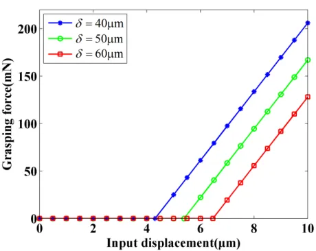
For FEA, the surfaces of the two fixing holes were fixed through applying zero
displacements, and the input displacements with a range from 0 μm to10μm were applied
on the input terminal of the wire clamp and the grasping force under the input
displacement was extracted when δ=40µm, δ=50µm and δ=60µm, respectively. The
relationship between the grasping force and the input displacement is summarized in
Fig.5.From Fig.5, it can be seen that the grasping force is zero before the jaws contact the
wire,andincreases linearly with the input displacement after contact. When δ=40µm,
δ=50µm and δ=60µm, the maximum grasping forces can reach 206.12mN, 167.08mN
11
Fig. 5Relationship between the grasping force and input displacement.
2.4Grasping force measurement
It is necessary to accurately measure the grasping forces before control them. The
stain gauge glued on flexible beam can sense the force applied to it as a change in
resistance, which is produced by the strain induced by the applied force. In order to
reduce the stress concentration of the flexible beam, two fillets are adopted to connect the
jaw and end of the parallelogram mechanism, respectively, which is shown in Fig. 1.
According to the bending deformation theory of flexible beams, the strain of the flexible
beam at the position of the stain gauge can be calculated as
2
6 s
b
FL EBh ε = (5)
whereF is the grasping force applied on the jaw, Ls
The resistance change of thestrain gauge is given by
is the distance between the point of
applying force and the strain gauge, E is the Young's Modulus of the material, B is the
12
0
= b g
R ε S R
∆ (6)
whereεbis the beamstrain, Sg is the gauge factor of the strain gauge and R0
The strain gauge is then connected to a Wheatstone bridge whose output is
connected to a dynamic strain gaugeto amplify the signal. The outputvoltage of the strain
gauge is given by
is the nominal
resistance of the strain gauge.
out
4 s b g b n
U = kε S U (7)
wheren denotes the number of the stain gauges inWheatstone bridge,ks is the
amplification ratio of the dynamic strain gauge, and Ub
Substituting Eq. (5) into Eq. (7),yields
is the excitation voltage of the
Wheatstone bridge.
out 2
3
2 s s g nk L S U
U F
EBh
= (8)
Based on Eq. (8), the following equation can be obtained:
out
F = ℜU (9)
where
2
2
3 s s g
EBh nk L S U
ℜ = .
Equation (9) describes the relationship between the grasping force applied on the
jaw and the outputvoltage of the strain gauge. It can be found that it is a linear
relationship between the grasping force and the outputvoltage on the condition that the
parameters of the flexible beam and the measurement system are certain. Therefore, the
grasping force measurement method is feasible.
13
3.1Prototype development and experimental setup
Figure 6 shows the prototype of the wire clampactuated by a SPCA (type: XP
5×5/18, output displacement: 0–18µm, applied voltage: 0–150V, maximum driving force:
1400N). The wire clamp was fabricated through wire electro-discharge machining(wire
EDM) technique to guarantee the geometrical accuracy of the crucial sections, and it was
made from the material of AL7075-T651, which has the property of high elasticity, yield
strength and light mass. The overall dimension of the wire clamp is 45 mm×28 mm×5
[image:14.612.168.445.326.522.2]mm, and the initial gap between the grasping jaws is 500 µm.
Fig. 6 The prototype of the wire clamp.
A laser displacement sensor (LK-H050 from Keyence, Inc) was employed to measure
the position of the grasping jaw, which provides a 50 nm resolution within a 20 mm
measuring range. A strain gauge (BE120-1AA from Sichuanger, Inc) was glued on the
base end of the flexible beam to form a quarter bridge for the grasping force measurement.
14
the gauge factor is 2.22. A dynamic strain gauge (SDY2105) was adopted to measure the
dynamic strain of the beam with the aid of the strain gauge and Wheatstone bridge. A
voltage amplifier (E505.00 from PI, Inc) was used to amplify the input voltage by an
adjustable gain of 10 for the SPCA actuation. The controller system of the prototype was
realized by the dSPACE DS1103 controller, which picks up the outputs from the grasping
force sensor system and the tip displacement sensor system to determine the state of the
wire clamp. According to the determined state of the wire clamp, the controller calculates
the control algorithm and generates the command voltage, which was applied to the
voltage amplifier to realize the corresponding operation. All the devices were placed on a
vibration-isolated Newport RS-4000 table and the experimental setup is displayed in
[image:15.612.186.428.403.678.2]Fig.7.
15
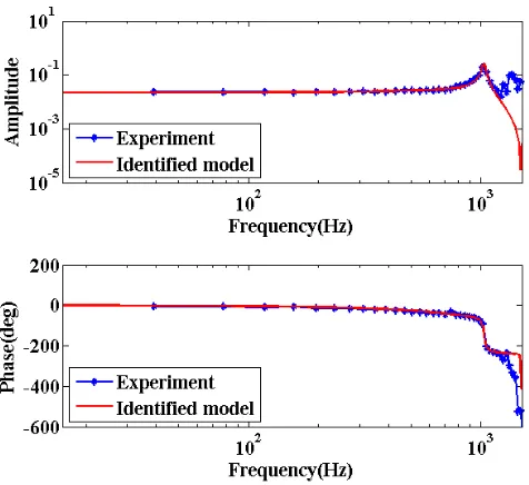
Fig. 8Results of system identification for the position.
Fig. 9Results of system identification for the grasping force.
3.2System identification
Experimental system identification based on the frequency response was adopted to
[image:16.612.179.417.347.565.2]16
waves with the amplitude of 0.6 V and frequency range of 0.1–1200 Hz were produced
by a dSPACE DS1103 controller to actuate the SPCA through the voltage amplifier in
order to obtain the experimental data to identify the two empirical models for position
/force control. During the identification of position model, the wire clamp was operated
freely, while a 25.4-µm gold wire was selected as a grasped object to identify force
model. The position response was measured by the laser displacement sensor, and
the force response was measured by the strain gauge. The output signals of position and
force responses were acquired within 10kHz, and then the Matlab System Identification
Toolbox was used to process the data, and the results are summarized in Figs 8 and 9.
The transfer functions of position and force are achieved from the input-output sequences,
and they are given as
3 7 2 11 14
4 3 7 2 10 14
7540 4.261 10 10 7.422 10
2976 3.213 10 7.421 1
3
0 +1.
.
496 10 097
( ) s
G s
s
s s s
s s s
− + × × + ×
+ + × + × ×
−
= (10)
6
2 7
1.726 10 ( )
217.3 4.193 10 f
G s
s s
× =
+ + × (11)
4. POSITION/FORCE SWITCHING CONTROLLER DESIGN
4.1Strategy of position/force switching controller
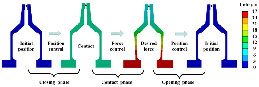
Since the distance between the two jaws is larger than the diameter of the wire, the
grasping task during the working process of wire clamp can be classified into three
phases, namely the closing phase, contact phase and opening phase. The closing phase
occurs prior to the contact of the jaws and wire, the contact phase begins from the touch
to the separation of the jaws and wire, and the opening phase is the subsequent time of
17
control are employed in the closing phase, contact phase and opening phase,
correspondingly, which is shown in Fig. 10. In this research, a strategy of position/force
switching controller was employed to regulate the position and force alternately. The
[image:18.612.95.516.208.350.2]position and force controller design can be seenin sections4.2 and 4.3, respectively.
Fig. 10Strategy of position/force switching control.
Algorithm 1 position/force switching control( dr, Fr, F0,t0)
1:Initialize ( dr, Fr, F0, t0)
2: if F < f0
3: (u
then
s1) position control (dr): u=fp(dr
4:else ift< t
)
0
5: (u
then
s2, ds) force control (fr, us1): u=fF(Fr)+ u
6: else
s1
7: position control (ds, us2): u=fp(ds)+ u
8: end if
18
Since the same control input voltage applied on the SPCA was adopted in the three
phases, the switching between each of the two phases may cause instability or undesired
responses of the position and force outputs. In order to guarantee a stable and smooth
transition between the two consecutive phases, the final voltage in previous phase should
be the base value for the next phase.In this way, a smooth transition between the two
phases can be accomplished [28]
The position/force switching control is shown in Algorithm 1, where F .
0 is the
threshold force, and t0 is the time to release the wire. During the closing phase, the
position control was employed to control the displacement of the grasping jaw following
a desired displacement dr until the grasping force Fexceeds the threshold force. The final
control voltage us1 can be obtained by the algorithm of position controlfp(dr). Once the
jaws touch the wire and the force sensor indicates the grasping force exceeding the
threshold force, the control system switches to the force control to regulate the grasping
force following the desired force Fr and the control voltage can be obtained through
adding the final voltage us1 in the closing phase to the voltage calculated by the algorithm
of force controlfF(Fr). When it is time to release the wire (t > t0), the control system will
switch to the position control again which controls the jaws to return to the initial position.
The control voltage can be calculated based on the final displacement ds and the final
voltage us2 in the contact phase which can be calculated by the algorithm of force
controlfF(Fr
4.2Position controller ).
The PID feedback loop has a simple structure, and the parameters of the PID
19
displacement of the grasping jawd to follow a desired displacement trajectorydr. The
transfer function of a traditional PID control can be expressed as
PID P D
I
1
( ) (1 )
G s K T s
T s
= + + (12)
whereKp is the proportional gain, TI is the integral time constant, and TD
Equation (12) can be written as
is the
differential time constant.
I
PID( ) P D
K
G s K K s
s
= + + (13)
where P
I I
K K
T
= is the integral gain andKD =K TP Dis the differential gain.
Defining e td( )=d tr( )−d t( ) as the position error, the PID position controller
equation is expressed as following:
P I
0
( )
( ) ( ) t ( ) d
d d d D
de t u t K e t K e t d t K
dt
= +
∫
+ (14)Generally, the PID controller can be adjusted with Ziegler-Nichols (Z-N) method by
several simulation studies, and then the parameters are tuned finely through experimental
investigations.
4.3Force controller
Considering there may be some dynamic force vibrations during the contact process,
sliding mode control with strong robustness to uncertainties and disturbances has been
adopted for the force control.The sliding model controller (SMC) design focuses on the
following domains: the selection of the sliding surface and the design of the sliding
20
Traditional SMC featured with PD-type sliding surface usually produces a slow
response speed while the SMC with PID-type sliding surface offers a faster transient
response and less steady-state error. Hence, SMC with PID-type sliding surface was
designed for the force control. According to the identified transfer function of grasping
force, the force model of the wire clamp during the contact phase can be written as
2
1 2 0
2
( ) ( )
( ) ( )
d f t d ft
a a f t b u t
dt + dt + = (15)
wherea1, a2 and b0
Assuming there is perturbation of the force system, and the perturbation p can be
written as
are constants, which can be confirmed by Eq. (11).
2
1 2 0
2
( ) ( )
( ) d f t d ft ( ) ( )
p t a a f t b u t
dt dt
= + + − (16)
The perturbation can be estimated by
2 *
1 2 0
2
( ) ( )
( ) ( ) d f t T d ft T ( ) ( )
p t p t T a a f t T b u t T
dt dt
− −
= − = + + − − − (17)
Then the force model can be expressed as
2
*
1 2 0
2
( ) ( )
( ) ( ) ( ) e( )
d f t d ft
a a f t b u t p t p t
dt + dt + = + + (18)
where *
( ) ( ) ( )
e
p t = p t −p t represents the error between the estimated perturbation and the
real perturbation of the system.
In the contact phase, the force controller was designed to control the grasping force f
between the grasping jaws and the wire to follow a desired force trajectory fr, and the
force error can be defined as
( ) ( ) ( )
f r
21
Then a sliding function of PID-type can be represented as
P I 0
( )
( ) f( ) t f( ) f
de t
s t c e t c e d
dt τ τ
= +
∫
+ (20)wherecP and cI
Designing the sliding control law as
are positive parameters and the parameters should be chosen strictly
Hurwitz. ] slaw ) ( ) [( 1 * I P 2 2 I 2 P 1 0 − − + + + − + −
= c f p
dt df c dt f d f c a dt df c a b
u r r r
SMC (21)
The exponential reach law is adopted as the reach law, and it can be expressed as
slaw= −ηsgn( )s −ks(22)
whereη >0and k>0 are constant parameters, and sgn(s) is the sign function.
Define a Lyapunov function as
2
2 s V = (23)
The first derivate of Eq. (23) can be obtained as
dV ds
s
dt = dt(24)
Differentiating Eq. (20) with respect to time, yields
e r
r
r a f bu p p
dt df a dt f d f f c dt df dt df c dt ds − − − + + + − + − = * 0 2 1 2 2 I
P( ) ( ) (25)
Then substitute Eqs. (21) and (25) into Eq. (24), and the following equation can be
22
If the gain η is designed to meet the condition
e p
η> +ε(27)
whereε>0 is an arbitrary constant, then the following relationship can be obtained:
2 2
0
e
dV
s ks p s ks s
dt = −
η
− − < − −ε
< (28)Equation (28) implies that the system is stable and the trajectory reaches the sliding
surface in finite time and remains on the sliding surface s=0. Besides, it also ensures that
the states will be confined to the surface s=0 for all future time since leaving the surface
requiresV to be positive, which is impossible as implied by the inequality.
Due to changes in the function sgn (s), when s is next to zero, the chattering problem
can appear. To avoid this undesirable effect, the sign function is substituted by a
saturation function with the following form:
1,
sat( ) ,
1, s
s
s s
s > ∆
=∆ ≤ ∆
− < −∆
(29)
where the positive constant∆represents the boundary layer thickness, which ensures that
s is always bounded by∆.
The sliding control law can be written as
(
)
(
)
2 *SMC 1 P 2 2 P I
0
1
[ r r + sat( ) ]
r
d f df
df
u a c a c f c c f p s ks
b dt dt dt η
= − + − + + + − + (30)
23
5.1Position control
Several control experiments were carried out to examine the performance of the
position/force switching controller. During the experiments, gold wires with a diameter of
25.4 µm were employed to verify the effectiveness of the switching control strategy.
Step response was investigated and the desired displacement trajectory was defined as
a step signal with a final value as 20 µm. The parameters of the position PID controller
are chosen as: KP=0.016, KI=45, KD=0.002. The step response of the position control is
shown in Fig. 11. From the result it can be seen that the setting time is 12 ms, the
overshoot is 2.5%, and the steady-state error is ±0.2 µm.
Fig.11Displacement step response of the wire clamp.
24
To compare the performance of PID force controller and sliding mode force
controller, step response was investigated and the desired force trajectory was defined as
a step signal with a final value as 50 mN. The parameters of the force PID controller are
chosen as: KP=0.5, KI=2100, KD=0.0015 and the parameters of the sliding mode
controller are chosen as cI=720, cP=129600, η=20, k=7500.These parameters are adjusted
by trial and error through experimental studies. Besides the threshold force F0 is 5mN.
The results of PID and sliding mode controllers are shown in Fig. 12. From the results it
can be seen that the setting time of PID controller is 30 ms, the overshoot is 1.3%, and the
steady-state error is ±0.4 mN. The setting time of sliding mode controller is 20 ms, the
overshoot is 1.8%, and the steady-state error is ±0.4 mN.It can be seen that the setting
time of sliding mode controller is less than that of PID controller.
Fig.12Results of PID and sliding mode controllers.
25
The jaw velocity in the closing phase is important in the transition between the
closing phase and contact phase, which can cause instability and undesired responses of
the force output. A series of experiments about different velocities have been
conducted. The PID controller was employed to control the displacement of the grasping
jaw, while the sliding mode controller was utilized to control the grasping force.
The parameters of controllers are the same with those in sections5.1 and 5.2. In the
closing phase the jaw was controlled by PID position controller to close at different
velocities of 100 µm/s, 200 µm/s, 300 µm/s, 400 µm/s, and 500 µm/suntil the grasping
force arrives at the threshold force F0. Then the grasping force was controlled by the
sliding mode force controller.The results of force control with different switching
velocities are shown in Fig. 13.It can be seen that the overshootsincrease with the
increase of switching velocitiesfrom 100µm/s to 400µm/s. The chattering phenomenon
which causes instability appears in the force response at velocity of 500 µm/s. Thus the
switching velocity can be in 0-500 µm/s to alleviate the chattering effect.The chattering
phenomenon may be caused by the jaw inertia or the controller and the related research
has been done in different applications [29]. In order to avoid the chattering
26
Fig. 13Results of force control with different switching velocities.
In order to achieve a complete and efficient grasp-hold-release operation, theposition
and force trajectorieswere planned and shown in Fig. 14. During the closing phase the
homothetic trapezoidal velocity planningwas employed to control the jaw displacement,
leading to the contact of the jaws and wire with a constant velocity. In the contact phase a
step force signal was utilized as the reference signal of the grasping force. In order to
make the jaws return to their initial positions, the trapezoidal velocity planning was used
27
Fig. 14Trajectory planning of position and force control.
Figure 15 shows the results of position/force switching control in the
grasp-hold-release operation. The parameters of position and force controller are the
same with those in sections5.1 and 5.2. A switching velocity of 200 µm/s and switching
time tsof 75 ms were chosen in the closing phase, and the desired force trajectory was
defined as a step signal with a final value as 50 mN in the contact phase. Besides the
threshold force of 10 mN was chosen to realize the switching from the closing phase to
contact phase. The results show that the steady-state error of grasping force is ±0.4 mN,
the setting time is 20 ms and the overall time of the operation is within 200
ms.Theresultsare compared with those reported in some similar works which are
summarized in Table 2. It is found that the developed wire clamp outperforms the others
in terms of a larger amplification ratio, high first vibration frequencyand faster overall
28
[image:29.612.167.425.80.558.2](a)
Fig. 15Results of position/force switching controlin the grasp-hold-release operation: (a) displacement response, and (b) force response.
29
Table 2Comparison with other similar works.
Actuation
Amplification
ratio
First vibration
frequency (Hz)
Overall
operation time
(s)
Position/force
control
Reference
Thermo-
Piezoelectric
- 667 120 Yes [30]
Voice coil
motor
- - >1 No [31]
Piezoelectric - 500 - Yes [32]
PZT 14.8 244 >5 Yes [28]
PZT 16 359.56 >12 No [33]
PZT 19.4 810 0.2 Yes This works
6. CONCLUSION
In this paper,the mechanism, characteristicsand control of a novel piezoelectric
actuated wire clamp have been reported. The grasping forces have been investigated
based on FEA, and the grasping force measurement has been described.Based on
frequency response approach, the transfer functions of position and force were achieved.
A position/force switching controller has been designed and employed to regulate the
position and force alternately, which is composed of a PID controller for the position
control and a slide model controller (SMC) for the force control. Experimental tests have
been carried out to investigate the performance of the wire clamp and the position/force
switching controllerduring the grasp-hold-release operation. The position step response
shows that the setting time is 12 ms, the overshoot is 2.5%, and the steady-state error is
30
controller is 30 ms, the overshoot is 1.3%, and the steady-state error is ±0.4 mN. The
setting time of SMC is 20 ms, the overshoot is 1.8%, and the steady-state error is ±0.4
mN. Obviously, the sliding mode force controller outperforms the PID force controller in
terms of the setting time. A series of experiments about different velocities have been
conducted, the result shows that the chattering phenomenon which may cause instability
appears in the force response at velocity of 500 µm/s,and the switching velocity can be in
0-500 µm/s to avoid the chattering effect.The control method to avoid the chattering
effect will be studied in future works. Finally position/force switching control in the grasp-hold-release operation has been investigated based on position and force trajectory
planning. The constant force regulation has been realized within 200 ms with the
steady-state force error ±0.4 mN.
ACKNOWLEDGMENTS
The experiment results show that the wire clamp
exhibits good performance and demonstrate that the new wire clamp and the control law
are well suited for fast and high precision grasping and releasing operations.
The supports of this work by the National Natural Science Foundation of China
(Grant nos. 51205279, 51275337 and 51175372), and the Science & Technology
Commission of Tianjin Municipality (Grant nos.13JCQNJC04100 and 15JCYBJC19600),
the Tianjin University for Peiyang Elite Scholar (Grant no. 60301014) and CSC
31
REFERENCES
[1] M.N.M. Zubir, B. Shirinzadeh, Y. Tian, Development of a novel flexure-based microgripper for high precision micro-object manipulation, Sensors and Actuators A: Physical,2009: 150(2): 257–266.
[2] H. Zhang, F. Wang, X. Zhao, D. Zhang, Y. Tian, Electrical matching of a piezoelectric ultrasonic transducer for microelectronic bonding, Sensors and Actuators A: Physical, 2013: 199(1): 241-249.
[3] Y Li, Q Xu, A novel piezoactuated XY stage with parallel, decoupled, and stacked flexure structure for micro-/nanopositioning, IEEE Transactions on Industrial Electronics, 2011: 58 (8): 3601–3615.
[4] F. Wang, X. Zhao, D. Zhang, Z. Ma, X. Jing, Robust and precision control for a directly driven XY table, Proceedings of IMechE, Part C, Journal of Mechanical Engineering Science, 2011: 225(5): 1107-1120.
[5] Z.W. Zhong, Overview of wire bonding using copper wire or insulated wire, Microelectronics Reliability, 2011: 51(1): 4-12.
[6] F. Wang, J. Li, S. Liu, X. Zhao, D. Zhang, Y. Tian, An improved adaptive genetic algorithm for image segmentation and vision alignment used in microelectronic bonding, IEEE/ASME Transactions on Mechatronics, 2014: 19(3): 916-923.
[7] F. Wang, D. Fan, Modeling and experimental study of a wire clamp for wire bonding. Journal of Electronic Packaging, 2015: 137(1): 011012.
[8] J. Liu, Y. Shi, P. Li, J. Tang, R. Zhao, H. Zhang, Experimental study on the package of high-g accelerometer, Sensors and Actuators A: Physical, 2012: 173(1): 1-8.
32
[10] D.M. Dozor, Magnetostrictive wire bonding clamp for semiconductor packaging: Initial prototype design, modeling, and experiments, Proceedings of SPIE - Industrial and Commercial Applications of Smart Structures Technologies, CA, USA, 1998: 3326: 516-526.
[11] D.K. Fan, F.L. Wang, Finite element analysis of wire clamp for wire bonding, Proceedings of International Conference on Electronic Packaging Technology & High Density Packaging, Guilin, China, 2012: 955-958.
[12] A. Pequegnat, H.J. Kim, M. Mayer, Y. Zhou, J. Persic, J.T. Moon, Effect of gas type and flow rate on Cu free air ball formation in thermosonic wire bonding, Microelectronics Reliability, 2011: 51(1): 43-52.
[13] C.T. Su, C.J. Yeh, Optimization of the Cu wire bonding process for IC assembly using Taguchi methods, Microelectronics Reliability, 2011: 51(1): 53-59.
[14] M. Rakotondrabe, I.A. Ivan, Development and force/position control of a new hybrid thermo-piezoelectric microgripper dedicated to micromanipulation tasks, IEEE Transactions on Automation Science and Engineering, 2011: 8(4): 824-834.
[15] C. Treesatayapun, Grasping force controller for parallel grip with fuzzy rules emulated networks, The International Journal of Advanced Manufacturing Technology, 2013: 68: 45-55.
[16] S. Wen, W. Zheng, J. Zhu, X. Li, S. Chen, Elman fuzzy adaptive control for obstacle avoidance of mobile robots using hybrid force/position incorporation, IEEE Transactions on Systems, Man, and Cybernetics, Part C: Applications and Reviews, 2012: 42(4): 603-608.
[17] N. Shimada, T. Yoshioka, K. Ohishi, T. Miyazaki, Novel force-sensor-less contact motion control for quick and smooth industrial robot motion, IECON 2011-37th Annual Conference on IEEE Industrial Electronics Society, 2011: 4238-4243.
[18] B. Gao, J. Shao, G. Han, G. Sun, X. Yang, D. Wu, Using fuzzy switching to achieve the smooth switching of force and position, Applied Mechanics and Materials, 2012: 274: 638-641.
33
[20] Q. Xu, M. Jia, Model reference adaptive control with perturbation estimation for a micropositioning system, IEEE Transactions on Control Systems Technology, 2014 22(1): 352-359.
[21] B.E. Helfrich, C. Lee, D. Bristow, X.H. Xiao, J. Dong, A.G. Alleyne, S.M. Salapaka, P.M. Ferreira, Combined-feedback control and iterative learning control design with application to nanopositioning systems, IEEE Transactions on Control Systems Technology, 2010: 18(2): 336-351.
[22] Y. Li, Q. Xu. Design and robust repetitive control of a new parallel-kinematic XY piezostage for micro/nanomanipulation, IEEE/ASME Transactions on Mechatronics,, 2012: 17(6): 1120-1132.
[23] F. Wang, Z. Ma, W. Gao, X. Zhao, Y. Tian, D. Zhang, C Liang, Dynamic modeling and control of a novel XY positioning stage for semiconductor packaging, Transactions of the Institute of Measurement and Control, 2015: 37(2): 177-189.
[24] Y Li, Q. Xu, Adaptive sliding mode control with perturbation estimation and PID sliding surface for motion tracking of a piezo-driven micromanipulator, IEEE Transactions on Control Systems Technology, 2010: 18(4): 798-810.
[25] C. Liang, F. Wang, Y. Tian, X. Zhao, H. Zhang, L. Cui, D. Zhang, P. Ferreira, A novel monolithic piezoelectric actuated flexure-mechanism based wire clamp for microelectronic device packaging, Review of Scientific Instruments, 2015: 86(4): 045106.
[26] N.Lobontiu, In-plane compliances of planar flexure hinges with serially connected straight-and circular-axis segments, Journal of Mechanical Design, 2014: 136(12): 122301.
[27] G.Palmieri, M.C.Palpacelli, M.Callegari, Study of a fully compliant u-joint designed for minirobotics applications, Journal of Mechanical Design, 2012: 134(11): 111003.
34
[29] A.Borboni, F.Aggogeri, A. Merlo, N.Pellegrini, C. Amici, PKM mechatronic clamping adaptive device, International Journal of Advanced Robotic Systems, 2015: 12: 42.
[30] M.Rakotondrabe and I.A. Ivan, Development and force/position control of a new hybrid thermo-piezoelectric microgripper dedicated to micromanipulation tasks, IEEE Transactions on Automation Science and Engineering, 2011: 8(4): 824-834.
[31]J. Park, S. Kim, D. Kim, B. Kim, S. Kwon, J. park, and K. Lee, Identification and control of a sensorized microgripper for micromanipulation, IEEE/ASME Transactions on Mechatronics, 2005: 10(5): 601-606.
[32]Q.Xu, Precision position/force interaction control of a piezoelectric multimorph microgripper for microassembly, IEEE Transactions on Automation Science and Engineering, 2013: 10(3): 503-514.