http://www.scirp.org/journal/ojapr ISSN Online: 2329-8413 ISSN Print: 2329-8421
DOI: 10.4236/ojapr.2017.54014 Dec. 14, 2017 180 Open Journal of Antennas and Propagation
Presentation of Design Equations for Array of
Circumferential Slot on Cylindrical Waveguide
Ali Khayati
1, Amir Amirabadi
2, Behnam Rajabi
31Islamic Azad University Parand Branch, Parand, Iran 2Islamic Azad University South Tehran Branch, Tehran, Iran 3Islamic Azad University Tuyserkan Branch, Tuyserkan, Iran
Abstract
In this paper the design equations for an array of circumferential slots on a cylindrical waveguide are obtained, following the procedure introduced by El-liott for slots on rectangular waveguides. The minimization of the error func-tion is achieved for optimizafunc-tion of slot array parameters. The optimizafunc-tion of slot parameters is not goal of this paper but a numerical example are pre-sented as illustrations of the proposed synthesis method. The results of array designs by the method of the least squares are verified by two computer simu-lation softwares, namely CST and HFSS.
Keywords
Array, Slot Arrays, Cylindrical Waveguide Slot Array, Cylindrical Waveguide, Circumferential Slot Array, Design Equations
1. Introduction
Train communication systems have received a considerable interest over the years, with tunnel connectivity providing an ongoing challenge due to the hostile environmental characteristics. In recent times, security aspects have come to the forefront with high-definition closed-circuit television monitoring being consi-dered, together with possible remote train control and passenger emergency as-sistance networks [1] [2][3][4][5]. The antenna applied for the broadcasting station of the ultra high frequency television (UHF TV) requires either unidirec-tional or omnidirecunidirec-tional beam with sufficient gain and high power handling [6].
The first study of radiation from an aperture on an infinite metallic plane was reported by Silver and Saunders in 1950, who derived a formula for the generat-ed external field [7]. Bailin derived formulas for the radiation from axial and How to cite this paper: Khayati, A.,
Ami-rabadi, A. and Rajabi, B. (2017) Presenta-tion of Design EquaPresenta-tions for Array of Cir-cumferential Slot on Cylindrical Wave-guide. Open Journal of Antennas and Propagation, 5, 180-187.
https://doi.org/10.4236/ojapr.2017.54014 Received: February 24, 2016
Accepted: December 11, 2017 Published: December 14, 2017
Copyright © 2017 by authors and Scientific Research Publishing Inc. This work is licensed under the Creative Commons Attribution International License (CC BY 4.0).
DOI: 10.4236/ojapr.2017.54014 181 Open Journal of Antennas and Propagation
circumferential rectangular slots on a conducting circular cylinder in 1955 [8] and compared his results with measurement data. Golden, et al. investigated some approximate techniques for the determination of mutual couplings among slots on cylindrical surfaces in 1974 [9]. We follow the general method intro-duced by Elliott [10] for the evaluation of scattering from an aperture on the surface of a cylindrical waveguide, which is believed to be unprecedented for the circumferential slots in a circular cylindrical surface. Consequently, our main task is to derive two design equations which is done by assuming that the radius of the cylindrical surface is large, providing the possibility of assuming the slots to be located on a flat ground plane. This assumption may lead to some design approximations, which may then be rectified by a full-wave simulation by avail-able computer softwares [11]-[14].
The TM01 mode is assumed in the cylindrical waveguide, where the electric
field is radial in its cross-section. Consequently, the radiation from the circum-ferential slots on its surface is omni-directional and independent of the azimu-thal angle, which is desired for cylindrical slot arrays.
2. Development of Design Procedure
2.1. First Design Equation
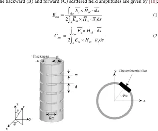
The configuration of circumferential rectangular slots on a cylindrical waveguide is shown in Figure 1, together with the related dimensions which the thickness parameter is the thickness of wall of waveguide, R is radius of waveguide, R
α
is length of slot, d is spacing between slots, W is width of slot and ϕ0 is the
an-gle offset of slot on circumference of cylindrical waveguide.
The backward (B) and forward (C) scattered field amplitudes are given by [10]:
slot d
2 d
s tC mn
at at z
S
E H s
B
E H u s
× ⋅
=
× ⋅
∫
∫
(1)slot d
2 d
s tB mn
at at z
S
E H s
C
E H u s
× ⋅
=
× ⋅
∫
[image:2.595.224.536.444.702.2]∫
(2)DOI: 10.4236/ojapr.2017.54014 182 Open Journal of Antennas and Propagation
where subscripts B and C represent the amplitudes of backward and forward waves, t indicates the tangential field in the cross-section, S indicates the cross- section of uniform waveguide, and “slot” shows the slot surface area.
The field components of TM01 mode in the cylindrical waveguide are:
( )
010 e
j z z
E =J h
ρ
±β (3)( )
0101 0 e j z j J E h h β
ρ = ±
β
′ρ
± (4)( )
010 e
j z j
H J h
h
β
ϕ = −
ω
′ρ
± (5)0
z
Eϕ =Hρ =H = (6)
where β01 is the phase constant and
2.405
h a
= is cut-off number with a being
the radius of waveguide.
The tangential electric field on the n’th aperture is:
(
0)
0 0 π cos 2 2 0 2 2 n z n n n n n W W
z z z
E V W
W
ϕ ϕ
α α
α ϕ ϕ ϕ
−
=
− < < +
<
<
− +
→ (7)
, 0
s z z
E =E u Eϕ = (8)
where αn is the angle of n’th slot. The other field component are:
tB
H =H uϕ ϕ (9)
tC
H =H uϕ ϕ (10)
at
H =H uϕ ϕ (11)
at
E =E uρ ρ (12)
These field components are substituted in Equations (1) and (2) to obtain:
( )
( )
( ) ( )
1
01 01 2 2
01 1 0 2
π π
n
n jV hJ ha
C B
a J ha J ha J ha
α
β
= =
−
(13)
Observe that the forward and backward traveling wave amplitudes are equal. Therefore the transmission line equivalent circuit consists of a parallel admit-tance.
The first design equation is then derived. The reflected power from the aper-ture is:
(
)
(
)
( ) ( )
*
2π * *
01 01, 01 01, 0 0
2
2 *
01
1 0 2 01 01
2 1 d 2 1 d d 2 π ( ) 2
ref S t t
a
t t z
E H
P Re s
Re B E B H u
a
J ha J ha J ha B B h
ρ ϕ ρ ρ ϕ
DOI: 10.4236/ojapr.2017.54014 183 Open Journal of Antennas and Propagation 01 1 01 2 at t at
B E z z
E
C E z z
<
=
>
(15)
The equations of the equivalent transmission line are:
( )
( )
0 0e e
e e
V V
j z j z
j z j z
I I
V z A B
I z AG BG
β β β β + − + − − − = + = − (16)
which give the reflected power:
( ) ( )
* * , 0 1 1 2 2 ref TL BBP V z I z
Z
− −
= = − (17)
The equality of reflected powers due to the scattered fields and the transmis-sion line leads to the following relation:
( )
( ) ( )
* 2
2 *
01 0
1 0 2 01 01
2 0 π 1 2 2 BB a
J ha J ha J ha B B
Z h
β ω
− = − (18)
However, the scattered voltage amplitudes are [7]:
0 1 2 a n n Y
B C V
G
= = − (19)
The amplitudes B and B01 from Equations (19) and (13) are then substituted in
(18) to obtain the first design equation:
( )
( )
0( ) ( )
5 2
0 01 1 0
2 1 0 2 4 π a s n n n n J ha
G J ha J ha J ha
Y V
j
G V
ω
β − α
= − (20)
where the Bessel functions J0, J1 and J2 are calculated for ha = 2.405 for
TM01 mode.
2.2. Second Design Equation
For the derivation of the second design equation, the procedure described by El-liott ([10], pp: 402-407]) is followed, which for the circumferential slots on cy-lindrical waveguides gives:
0 2 2 2 , 0 2 a n n d n Y K
G G z α
α η
= (21)
where
( )
( )
0( ) ( )
5 2 0 1 1 0 2 2 4 π J ha G J ha J ha J j ha K ω β = − −
DOI: 10.4236/ojapr.2017.54014 184 Open Journal of Antennas and Propagation
impedance of medium and G0 is characteristics admittance of cylindrical
waveguide. Equation (21) can be written as
2 1 , 0 a n n d a n Y K G Z
α
= where
2 2
1 0
2
K =η G K . d a,
n
Z is the active admittance of equivalent dipole that is
as-sumed in the derivation of second design equation. we have ,
n d a n b n n Z Z = +Z
where:
nn
Z : Self impedance of circumferential slot, which is equal to 2 1 0 n self n K Y G
α
b nZ : Mutual impedance between circumferential slots on the cylindrical
wa-veguide, which is equal to 1
s
N m d
m s nm
m n n V Z V = ≠
∑
. Then 2 , 1 1 0 s Nd a b n m d
m
n nn n self s nm
m n
n n
K V
Z Z Z Z
Y G V
α
= ≠ = + = +∑
d nmZ is mutual impedance between two dipole which may be obtained from
the mutual admittance between two slots s nm
Y by the Booker’s relation.
2
2
d s
nm nm
Z = η Y
(22)
The second design equation is then determined by these relations.
3. Design of a Linear Traveling Wave Slot Array
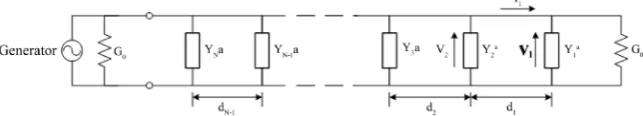
[image:5.595.200.547.28.774.2] [image:5.595.213.535.647.705.2]Consider the equivalent circuit of the linear traveling wave slot array as shown in Figure 2. The normalized admittance at the n’th slot looking towards the match port is [10]:
(
)
(
)
2
1 0 10 1 10 1
1 ,
0 10 1 1 0 10 1
cos sin cos sin
n n n
n n
d a
n n n
n
Y G d j d
Y K
G Z d j Y G d
β β α β β − − − − − − + = +
+ (23)
where the second design Equation (21) is used.
The mode voltages at successive junctions are then related by:
1 01 1 1 0 01 1
1
1 01 1 01 1
0
cos sin
cos sin
n n n n n
n
n n n
V V d jI Z d
Y
V d j d
G β β β β − − − − − − − − = + = + (24)
which may be written for
1 n
n V V−
. This ratio may also be obtained by Equation
DOI: 10.4236/ojapr.2017.54014 185 Open Journal of Antennas and Propagation
(18) for n and n − 1. Equating these two ratios gives:
(
)
1(
)
1 001 1 01 1
0 1 1 0
cos sin
s a
n n n n
n n s a
n
n n
Y V Y G
d j d
G V Y G
α
β
β
α
− −
− −
− −
+ = ⋅ ⋅ (25)
This expression is appropriate for the construction of an error function.
4. Construction of Error Function
The error function consists of three terms:
Error Function Matching DesignEqs.
ε =ε +ε (26)
Matching
2
2 0 1
0 2
Re Yn 1 Im n
W Y
G W G
ε = − +
(27)
(
)
1(
)
,1 0DesignEqs. 1 1 ,
0 1 1
3 2
0 2
cos sin
s d
N n n n n a
n n s d a
n
n n
n
Y V Y G
d j d
G V Y G
W α
ε β β
α
− −
− −
− − =
= −
+ ⋅ ⋅
∑
(28)where
The error function depends on the slot spacings and angular dimensions and will be used for optimizing slot parameters by minimizer algorithms such as gradient conjugate or genetic algorithm.
Modified Taylor Pattern at 5.35 GHz
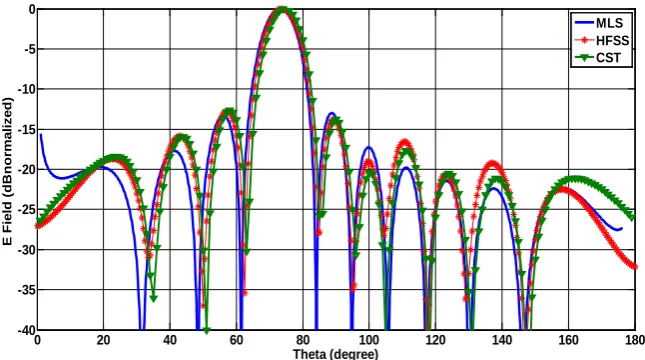
The cylindrical slot array is designed for 13 slots at the frequency 5.35 GHz. The design parameters of the array are given in Table 1. The pattern of slot array as obtained by the MLS and computer simulations by CST and HFSS are in Figure 3, for comparison. The VSWRs of array at the input port of cylindrical wave-guide are drawn in Figure 4.
5. Conclusion
[image:6.595.211.534.523.703.2]In this paper the design equations are developed for the traveling wave mode by
Figure 3. Comparison of patterns by MLS, HFSS and CST at 5.35 GHz.
0 20 40 60 80 100 120 140 160 180
-40 -35 -30 -25 -20 -15 -10 -5 0
Theta (degree)
E
F
ie
ld
(
d
B
n
o
rm
a
li
z
e
d
)
DOI: 10.4236/ojapr.2017.54014 186 Open Journal of Antennas and Propagation
Figure 4. Diagram of VSWR Simulated by HFSS and CST softwares.
Table 1. The parameters and specifications of cylindrical slot array.
13 Number of slots
Antenna parameter
5.60 mm Slot width: W
0.20 mm Thickness of waveguide wall: Thickness
22.43 mm Radius of cylindrical waveguide: R
5.35 GHz Operation frequency
15.70 mm
Slot length: Rα
Optimized parameters
23.05 mm Slot spacing: d
Modified Taylor pattern with SLL = −13 dB Characteristics of desired pattern
employing the equivalent circuits according to the Elliott’s method. The geome-trical dimensions of the slot array on the cylindrical surface are determined by the minimization of the appropriate error functions. The proposed synthesis method of cylindrical slot array is demonstrated by one design example at 5.35 GHz frequency and is verified by simulation softwares of CST and HFSS. Such arrays are appropriate for various platforms of cylindrical shape, such broad-casting transmitter antennas (TV station).
References
[1] Santos, A.J.D., Soares, A.R., De Almeid Redondo, F.M. and Carvalho, N.B. (2005) Tracking Trains via Radio Frequency Systems. IEEE Transactions on Intelligent Transportation Systems, 6, 244-258. https://doi.org/10.1109/TITS.2005.848369
[2] Emslie, A., Lagace, R. and Strong, P. (1975) Theory of the Propagation of UHF Ra-dio Waves in Coal Minetunnels. IEEE Transactions on Antennas and Propagation, AP-23, 192-205. https://doi.org/10.1109/TAP.1975.1141041
[3] Chen, W.-K. (1993) Linear Networks and Systems. Belmont. Wadsworth, Boston, 123-135.
[4] Pisard, W., De Keyser, R., Hellin, H. and Deryck, L. (1998) Wireless Image Trans-mission in Tunnels with Analogue Video Systems. Proceeding 3rd International Conference Safety Road Rail Tunnel, Nice, Mar 1998, 1-13.
5.32 5.325 5.33 5.335 5.34 5.345 5.35 5.355 5.36 5.365 5.37 5.375 5.385.38 1.05
1.07 1.09 1.11 1.13 1.15 1.17 1.19
Frequency ( GHz )
VSW
R
DOI: 10.4236/ojapr.2017.54014 187 Open Journal of Antennas and Propagation
[5] Poor, H. (1985) An Introduction to Signal Detection and Estimation. Sprin-ger-Verlag, NewYork.
[6] International Telecommunication Union (1995) Transmitting Antenna Characte-ristics at VHF and UHF, Recommendation ITU-R BS.I195. International Tele-communication Union, Geneva.
[7] Silver, S. and Saunders, W.K. (1950) External Field Produced by a Slot in an Infinite Circular Cylinder. Applied Physics, 21, 153-158. https://doi.org/10.1063/1.1699615
[8] Bailin, L.L. (1955) The Radiation Field Produced by a Slot in a Large Circular Cy-linder. IRE Transactions on Antennas and Propagation, 3, 128-137.
https://doi.org/10.1109/TAP.1955.1144301
[9] Golden, K.G., Stewart, G.E. and Pridmore-Brown, C. (1974) Approximation Tech-niques for the Mutual Admittance of Slot Antennas on Metallic Cones. Antennas, 22, 43-48. https://doi.org/10.1109/TAP.1974.1140727
[10] Elliott, R.S. (2003) Antenna Theory and Design, Revised Edition. IEEE Press, New Jersey, 91, 467-474. https://doi.org/10.1109/9780470544174
[11] Oraizi, H., Behbahani, A.K., Noghani, M.T. and Sharafimasouleh, M. (2013) Opti-mum Design of Travelling Rectangular Waveguide Edge Slot Array with Non-Uniform Spacing. Journal of Microwaves, Antennas and Propagation IET, 7, 575-581. https://doi.org/10.1049/iet-map.2012.0438
[12] Masouleh, M.S. and Behbahani, A.K. (2016) Optimum Design of the Array of Cir-cumferential Slots on a Cylindrical Waveguide. AEU-International Journal of Elec-tronics and Communications, 70, 578-583.
https://doi.org/10.1016/j.aeue.2016.01.010
[13] Azarbar, A., Masouleh, M.S. and Behbahani, A.K. (2014) A New Terahertz Micro-strip Rectangular Patch Array Antenna. International Journal of Electromagnetics and Applications, 4, 25-29.
[14] Azarbar, A., Masouleh, M.S., Behbahani, A.K. and Oraizi, H. (2012) Comparison of Different Designs of Cylindrical Printed Quadrifilar Helix Antennas. Computer and Communication Engineering (ICCCE), Kuala Lumpur, 3-5 July 2012.