THE AUSTENITISATION AND DECARBURISATION
OF HIGH SILICON SPRING STEELS
A thesis submitted in fulfilment
of the requirements for the Degree
of
Doctor of Philosophy in Engineering
at the University of Canterbury
by
Chris Mardon
University of Canterbury Christchurch, New Zealand.
ABSTRACT
The 1970’s saw the demand for more fuel efficient vehicles. This necessitated lighter
automobiles, and was partly attained by lowering the weight of the coil springs used for the suspensions of these vehicles. Substantial weight reductions were achieved with new steels such as SUP7, with their elevated carbon and silicon contents allowing the springs to operate at higher stresses. However, these steels are prone to decarburisation during spring manufacture, which sharply reduces the sag resistance and the fatigue strength of the springs. The literature pertaining to the decarburisation of high silicon spring steels is limited, despite the subsequent reduced sag and fatigue properties.
The research detailed in this thesis was therefore undertaken to investigate the decarburisation of spring steels with 0 to 3wt.% silicon for a range of temperatures and heat treatment atmospheres. The austenitisation of these steels was also investigated to provide complementary information. Austenitisation and decarburisation heat treatments were undertaken with 0, 1 and 3wt.% silicon experimental steels, and the commercially available 2wt.% silicon SUP7 and SUP7NV steels. These five steels have similar carbon, manganese and chromium contents.
Two dimensional austenite growth occurred for the different steels, with the austenite grain shape inherited from the initial ferrite grain structure. The austenitisation accelerated with increasing temperature, with the higher silicon steels exhibiting faster transformation kinetics at comparable intercritical fractional superheat temperatures due to the higher Ac1 and Ac3
An increasing silicon content up to 2wt.% increased the rate of carbon removal at comparable temperatures. Multiple linear regression analysis demonstrated that the mass of carbon removed during decarburisation increased with silicon contents up to 2wt.%, with temperature, and with
2 2O/ H
H p
p ratios of 0.01 to 0.25, while manganese decreased the decarburisation. However, slower decarburisation resulted for the 3% Silicon steel, especially at higher temperatures and lower
2 2O/ H
H p
p ratios, where a dense oxide layer strongly
inhibited carbon removal. The decarburisation of the 1% Silicon, SUP7 and SUP7NV steels was fastest at their respective Ac3 temperatures. Columnar free ferrite grain structures were
obtained for the 0% Silicon and SUP7 steels, compared with equiaxed grains for the 1% Silicon, SUP7NV and 3% Silicon steels.
The decarburisation of SUP7 was fastest when the specimen was heated in the furnace with the heat treatment atmosphere already established, while slower decarburisation resulted when the specimens were annealed in inert atmospheres prior to the introduction of the decarburisation atmosphere. Different initial SUP7 microstructures influenced the carbon release kinetics as the specimens heated to temperature. Prolonged decarburisation of SUP7 and SUP7NV at 900°C yielded decreasing free ferrite depths after 4hr, despite continued carbon removal from the steel.
ACKNOWLEDGEMENTS
I would like to say a grateful thankyou to the following who have assisted in my research:
BHP New Zealand Steel for their generous financial assistance from 1993 to 1995.
Geoff “Danger Mouse” Leathwick for obtaining “anything and everything” that I required.
Ken Brown and Otto Bolt for their “mass production” of countless test specimens.
Mike Flaws, Dave Healy, Hugh Mobbs and Kevin Stobbs for “valuable” materials support.
Eric Cox and Ron Tinker for supplying the “related incidentals”.
Julian Phillips for helping construct “salt baths Mark I, II, III, IV, V, VI, VII and VIII”.
Paul “SMF” Southward for his “skills on the computer”.
The various “Chunky Chipmunk” postgrad guys and gals for “advice and entertainment”.
John Smaill for being there when I started, being there when I finished, and making sure that I “did the bits in-between”.
Thomas “Sleeve” and “Sex is Short Stay Hard Reebonk” Mackenzie for “making me look
outside the sphere and not be afraid to be different”.
Mum, Dad, Simon and Rachael in Nelson for their question “when will I finish”.
Never ever give up. If you fail 99 times,
try a 100th time,
because if you keep trying despite always failing, you will eventually succeed.
This thesis is presented in acknowledgment of the financial support for
C. A. Mardon from 1993 to 1995 by BHP New Zealand Steel Limited.
C.A. Mardon Dr. J. S. Smaill Professor J. K. Raine
Recipient of the BHP Supervisor Head of Department
New Zealand Steel Department of Mechanical Department of Mechanical
Scholarship 1993-1995 Engineering Engineering
TABLE OF CONTENTS
LIST OF FIGURES vii
LIST OF TABLES xxiv
NOMENCLATURE xxvi
1 INTRODUCTION
1.1 Fundamentals of spring steels 1
1.2 Modern automobile suspension spring steels 2
1.3 Manufacture and heat treatment of automobile suspension springs 6
1.4 Scope and outline of thesis 8
2 FORMATION OF AUSTENITE IN STEELS
2.1 Nucleation and growth of austenite 12
2.1.1 Low carbon steels 14
2.1.2 Pearlitic steels 15
2.1.3 Spheroidised steels 16
2.2 Austenite formation and carbide dissolution kinetics 18
2.2.1 Austenite transformation 18
2.2.2 Carbide dissolution 21
2.3 Influence of alloying elements on austenitisation 22
3 DECARBURIZATION OF STEELS
3.1 Introduction 27
3.2 Decarburisation of plain carbon steels 28
3.2.1 Decarburisation in the intercritical temperature range 28
3.2.2 Decarburisation at the Ac3 temperature 29
3.3 Decarburisation environments 34
3.4 Decarburisation of higher silicon steels 35
3.4.1 Influence of alloy content 35
3.4.2 Influence of temperature 37
3.4.3 Influence of decarburisation atmosphere 38
3.5 Oxidation of silicon steels 41
3.5.1 Fundamentals of oxidation 41
3.5.2 Influence of heat treatment atmosphere on oxidation 44
3.5.3 Influence of silicon content 50
3.6 Mechanisms of decarburisation 52
3.6.1 Thermodynamic principles 53
3.6.2 Gas diffusion in the boundary layer 57
3.6.3 Surface reactions 57
3.6.4 Diffusion in steel 58
3.6.5 Kinetics of the decarburisation reactions 60
4 DIFFUSION IN STEELS
4.1 Diffusion mechanisms 71
4.1.1 Interstitial diffusion 71
4.1.2 Vacancy mechanism 73
4.1.3 Place exchange mechanism 74
4.1.4 Ring-type mechanism 74
4.2 Diffusion of carbon in steel 74
4.2.1 Influence of alloying elements on diffusion 75
4.2.2 High diffusivity paths 78
5 EXPERIMENTAL PHILOSOPHY
5.1 Outline of research areas 81
5.2 Description of research areas 83
5.2.1 Austenitisation investigation 83
5.2.2 Decarburisation investigation 85
5.3 Experimental design 86
5.3.2 Decarburisation experimentation 89
6 EXPERIMENTAL APPARATUS
6.1 Introduction 91
6.2 Salt bath 91
6.2.1 Design philosophy 91
6.2.2 Salt bath experimental layout 93
6.2.3 Salt bath furnace control 95
6.3 Austenitisation heat treatment rig 95
6.4 Decarburisation heat treatment rig 96
6.4.1 Design philosophy 96
6.4.2 Test rig layout 97
7 EXPERIMENTAL TECHNIQUES
7.1 Introduction 103
7.2 Production of the experimental steels 103
7.3 Preparation of test specimens 104
7.4 Salt bath austenitisation heat treatments 107
7.5 Tube furnace austenitisation heat treatments 108
7.6 Decarburisation heat treatments 110
7.6.1 Heat treatments 110
7.6.2 Infrared gas analysis of decarburisation atmosphere 115
7.7 Specimen preparation for microstructural analysis 116
7.7.1 Austenitisation specimens 116
7.7.2 Decarburisation specimens 117
8 ANALYTICAL TECHNIQUES
8.1 Introduction 121
8.2 Initial microstructures 123
8.2.1 Prior austenite grain size 123
8.2.2 Pearlite true interlamellar spacing 126
8.2.5 Energy Dispersive X-Ray Spectrum Analysis of alloying elements 134
8.3 Austenitisation heat treatments 136
8.3.1 Austenite formation 136
8.3.2 Cementite dissolution 139
8.3.3 Ferrite grain size 140
8.3.4 Energy Dispersive X-Ray Spectrum Analysis of alloying elements 140
8.3.5 Microhardness 141
8.4 Decarburisation heat treatments 141
8.4.1 Decarburisation depth measurements 141
8.4.2 Oxidation thickness measurements 143
8.4.3 Decarburised ferrite grain structures 144
8.4.4 Energy Dispersive X-Ray Spectrum Analysis of alloying elements 145
8.4.5 Analysis of infrared gas data 146
8.4.6 Microhardness profiles 153
9 AUSTENITISATION HEAT TREATMENTS
9.1 Introduction 155
9.2 Preliminary experimentation 155
9.2.1 Determination of transformation temperatures 155
9.2.2 Initial microstructures 157
9.2.3 Quantitative description of the initial microstructures 161
9.3 Microstructural investigation 166
9.3.1 Influence of temperature on austenitisation 166
9.3.2 Austenite nucleation and growth 167
9.4 Austenitisation kinetics 176
9.4.1 Austenitisation kinetics for the different silicon steels 176
9.4.2 Detailed SUP7 austenitisation kinetics 180
9.5 Comparison of austenitisation kinetics for the different silicon steels 193
9.6 Cementite dissolution kinetics 197
9.7 Determination of austenite carbon contents 200
9.8 Microalloy element partitioning 203
9.9 Austenite nucleation and growth mechanisms 204
10 SUP7 DECARBURISATION HEAT TREATMENTS
10.1 Introduction 215
10.2 Dependence of decarburisation on hydrogen flow rate 216
10.3 Decarburisation with prior heating to and austenitisation at the Ac3
temperature 220
10.3.1 Microstructural investigation 221
10.3.2 Decarburisation kinetics 222
10.3.3 Oxidation kinetics 225
10.3.4 Free ferrite columnar structures 225
10.3.5 SUP7 decarburisation with no heating 226
10.4 Influence of water content on decarburisation at the Ac3 temperature 233
10.5 Influence of temperature on decarburisation 235
10.5.1 Microstructural investigation 235
10.5.2 Decarburisation kinetics 235
10.5.3 Oxidation kinetics 238
10.5.4 Free ferrite columnar grain growth kinetics 238
10.6 Further decarburisation experiments 239
10.6.1 Interrupted decarburisation tests 239
10.6.2 Further investigation into austenitisation prior to decarburisation 240
10.6.3 Carbon removal during specimen heating 243
10.7 Summary of decarburisation investigation 246
11 INFLUENCE OF SILICON CONTENT ON DECARBURISATION
11.1 Introduction 249
11.2 Microstructural investigation 249
11.2.1 Influence of
2 2O/ H
H p
p ratio 249
11.2.2 Influence of temperature 251
11.3 Infra-red gas analysis data 252
11.3.1 Decarburisation of the 0% Silicon steel 252
11.3.2 Decarburisation of the 1% Silicon steel 253
11.3.3 Decarburisation of SUP7NV 253
Ac3 temperatures 255
11.3.6 Temperature dependence of decarburisation for the different
silicon steels 256
11.3.7 Multiple linear regression analysis 258
11.4 Free ferrite decarburisation kinetics for the different silicon steels 260 11.5 Oxide layer thicknesses for the different silicon steels 262
11.6 Oxidation structures of the different silicon steels 264
11.6.1 Microstructural investigation 264
11.6.2 Quantitative determination 265
11.6.3 Identification of oxide structures 268
11.7 Decarburisation discussion for the different silicon steels 272 11.7.1 Calculation of effective diffusion coefficients 272
11.7.2 Microhardness profiles 275
11.7.3 Calculation of carbon removed during decarburisation 276
11.7.4 Decarburisation in air 279
11.7.5 Decarburisation of SUP7 and SUP7NV 280
11.7.6 Description of the factors contributing to decarburisation 281
11.8 Summary of decarburisation investigation 288
12 CONCLUSIONS 291
13 RECOMMENDATIONS FOR FUTURE RESEARCH
13.1 Implications of results to spring manufacture 299
13.2 Future research 300
REFERENCES 303
APPENDICES
A Salt bath furnace design calculations A1
B Specification of silicon carbide electric heating elements A4
C Nominal composition of heat treatment gases A6
D Variation of pH O pH
2 / 2 ratio with water temperature A8
F Calculation of water transported by hydrogen flow A14 G Calculation of alloy additions for production of experimental steels A16 H Calibration of decarburisation test rig pressure transducers A19
I Etchants and chemical solutions A22
J Calibration of infrared gas analysers A27
K Image analysis programs A31
K1 Measurement of pearlite true interlamellar spacing A32
(i) PEARST2 A32
(ii) PEARAN2 A32
K2 Measurement of initial cementite structures A34
(i) CEMSTI A34
(ii) CEMANI A35
K3 Measurement of martensite structures with predominantly discrete
martensite particles A40
(i) STARTM3 A40
(ii) ANALYM3 A41
K4 Measurement of martensite structures with significant coalescence
of martensite particles A43
(i) STARTM2 A43
(ii) ANALYM2 A43
K5 Measurement of cementite structures during austenitisation A45
(i) CMNSEST A45
(ii) CMNSEAN A45
L Papers published A49
(i) IPENZ94 A50
(ii) IPENZ97a A62
(iii) IPENZ97b A74
(iv) IPENZ98a A80
(v) IPENZ98b A92
LIST OF FIGURES
1.1 General automobile spring manufacturing processes 2
2.1 Mechanisms for the austenitisation of steel 12
2.2 Possible nucleation sites for austenite 14
2.3 Time-temperature iso-transformation diagram for a 0.78wt.%C pearlitic steel 16
2.4 Influence of temperature on austenitisation kinetics of a 0.95 wt.%C tool steel 19
2.5 Decrease in the ferrite volume fraction during austenitisation of a 0.80wt.%C
/2.02wt.%Si/2.06wt.%Mn/1.05wt.%Cr steel at 820°C 20
2.6 Transformation kinetics for a 1.27 wt.%C steel 22
2.7 Influence of annealing temperature on the partitioning of alloying elements for
a 0.80wt.%C/2.06wt.%Mn/2.02wt.%Si/1.05wt.%Cr steel 23
2.8 Manganese concentration profiles for a 0.11wt.%C/0.73wt.%Si/1.60wt.%Mn
Steel 24
3.1 Left hand portion of the Fe-C equilibrium diagram 28
3.2 Carbon profiles for decarburisation 29
3.3 Decarburisation above the Ac3 temperature 30
3.4 Dependence of decarburisation rate, c, of a Fe/0.06wt.%C steel on the
annealing temperature 32
3.5 Decarburisation profiles of electrical steels at 850°C showing the mass change
per area, c 36
3.6 Influence of silicon content on decarburisation rate, c, of low carbon steels 36
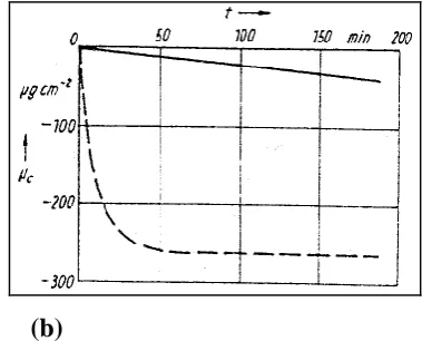
3.7 Decarburisation of a 2.87wt.%Si electrical steel at pH O pH
2 / 2=0.245 38
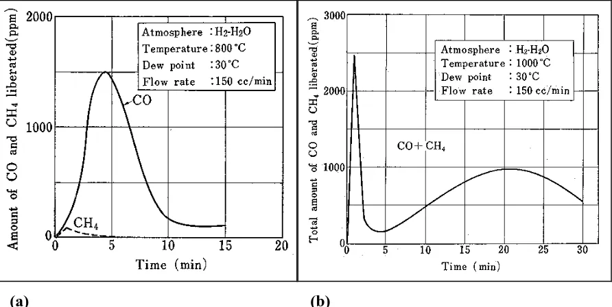
3.8 Decarburisation of a 3wt.%Si electrical steel 39
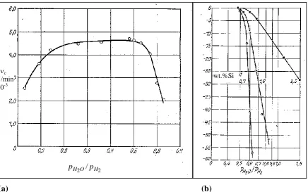
3.9 Decarburisation rate for a 0.04wt.%C/0.68wt.%Si/0.31wt.%Mn steel 40
3.10 4min decarburisation of a 2.87wt.%Si steel as a function of pH O pH
2 / 2 ratio 40
3.11 Oxidation of a metal through a protective oxide layer 42
3.12 Growth kinetics of the external and internal oxidation zones of a 0.006wt.%C/
1.74wt.%Si steel with a 50 vol.% CO2 atmosphere at atmospheric pressure 45
3.13 Scale structures for oxidation in still air, and in CO2 46
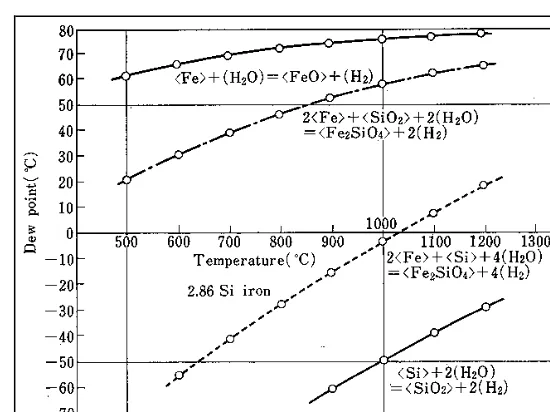
3.14 Relationships between pH O pH
2 / 2 ratio and temperature for the potential
3.15 Oxidation of a 0.021 wt. %C/2.96wt. %Si steel for lhr at 850°C illustrating the
influence of p H
2o I p H2 ratio 49
3.16 Alloy element concentration profile of oxidised layer for lOmin decarburisation of a Fe-3wt. %Si steel at 801
ac,
p H2o I p H2 =0.20 49
3.17 Influence of silicon content on the specific mass change, ~0,1, for Si02
formation during the decarburisation of electrical steels 50
3.18 Silicon and iron concentration profiles for a ferritic Fe-1.5wt. %Si alloy across the
scale and alloy for 24hr oxidation in 50 vol.% C02 at atmospheric 51
3.19 Oxidation of a Fe-1.5wt. %Si steel in a 50 vol.% C02 atmosphere 52
3.20 Steps involved in decarburisation of steel sheet 53 3.21 Dependence of the decarburisation rate in wet hydrogen mixtures divided by the
4.1
4.2
4.3
4.4
carbon concentration, on the p H
2o I p H2 ratio lllustration of diffusion mechanisms
Schematic illustrations of annular diffusion Diffusivity spectrum for metals
Diffusion grain boundary migration
6.1 Comparison of heating rates for 16mm diameter steel bars in lead, salt bath, fluidised bed, and conventional air furnaces
6.2
6.3
6.4
6.5
6.6
Layout of salt bath furnace
Salt bath element and electrode layout Salt bath controller
Salt bath control equipment
Austenitisation/decarburisation test rig
6.7 Schematic illustration of the generation of a water/hydrogen decarburisation atmosphere
6.8 The water baths used to saturate hydrogen with water
6.9 Schematic illustration of the tube furnace hot zone arrangement 6.10 Exhaust gas analysis apparatus
6.11 Schematic layout of the austenitisation/decarburisation test rig 7.1 Test specimens
7.2 Influence of silicon content on the theoretically determined Ac1 and Ac3
7.3 Heating profiles for 5mm diameter by 50mm test specimens inserted into the tube furnace hot zone at the respective Ac3 temperatures for furnace cooled
initial structures of the different steels 110
7.4 Heating profiles for 5mm diameter by 15 and 50mm SUP7 furnace cooled
initial specimens inserted into the tube furnace hot zone at 820°C 110
7.5 Decarburisation test specimen holder with four 5mm diameter by 15mm SUP7
test specimens 112
7.6 Typical calibration curves for the CO and CO2 infrared gas analysers 116
7.7 Comparison of 2% Nital and sodium metabisulphite etchants 116
7.8 Schematic illustration of the electroless nickel plating apparatus 118
8.1 Prior austenite grain boundaries for the 0% Silicon steel austenitised for 12hr
at 900°C and quenched in water 124
8.2 SEM laser printout of a SUP7 furnace cooled initial structure 126
8.3 Laser printout of a SEM SUP7 12hr tempered martensite initial microstructure 126
8.4 Illustration of the microstructure of a SUP7 96hr tempered martensite initial structure austenitised at 755°C for 24hr and etched with 2% Nital followed by
sodium metabisulphite to darken the martensite 136
8.5 Optical microscope placement pattern at 50x magnification for image analysis
of the austenitisation structures 137
8.6 Microphotos demonstrating the decarburisation structures 142
8.7 Optical microscope placement pattern for decarburisation depth measurements 143
8.8 Surface oxide structure of a 5mm diameter by 15mm SUP7 furnace cooled specimen decarburised for 24hr at 820°C with prior heating and austenitisation,
pH O2 / pH2=0.25 144
8.9 Pen recorder data for carbon monoxide and carbon dioxide gases evolved during decarburisation of a 5mm diameter x 50mm SUP7 air cooled specimen at 820°C with pH O pH
2 / 2=0.05 146
8.10 Carbon monoxide and carbon dioxide gas compositions during decarburisation of a 5mm diameter x 50mm SUP7 12hr tempered martensite initial structure for the first 15min at 820°C with pH O pH
2 / 2=0.05 146
8.11 Carbon concentration profile in ferrite and austenite for decarburisation at the
8.12 Schematic illustration of the cross-section for a test specimen at an intermediate
stage of decarburisation at the Ac3 temperature 151
8.13 Variation of correction factor with decarburisation depth for different cylindrical
test specimens 152
8.14 Microindentation profile for a 5mm diameter x 50mm 0% Silicon furnace
cooled initial structure decarburised for 4hr at 900°C with p820 I p82 =0.05 152
9.1 Dilatometry curves for heating and cooling of SUP7 at 2°C/min
9.2 Microstructures obtained during determination of the Ac1 and Ac3 SUP7
temperatures
9.3 The six initial SUP7 microstructures
9.4 Initial austenitisation microstructures for the different silicon steels
9.5 Pearlite mean true interlamellar spacings for the pearlitic structures of the different silicon steels
9.6 Cementite volume fractions for the spheroidal cementite structures of the different silicon steels
9.7 Cementite particle size distribution for 96hr tempered martensite initial structures of the different silicon steels
9.8 Cementite particle size distribution for different initial SUP7 spheroidal cementite structures
9.9 Cementite particle mean equivalent area diameters for the spheroidal cementite structures of the different silicon steels
9.10 Ferrite and cementite alloying element concentrations for 96hr tempered martensite and intercritical structures of the different silicon steels
9.11 Microstructures obtained after austenitisation of SUP7 furnace cooled and 96hr
156
158 158 160
162
162
164
164
164
164
tempered martensite initial structures 166
9.12 Influence of initial structure on SUP7 austenitisation after 30s at 820°C 168 9.13 Microstructures of 0% Silicon steels heat treated at 723oC 168
cooled initial structures for the different silicon steels 172
9.19 Austenitisation microstructures of 96hr tempered martensite initial structures
at the Ac3 temperatures for the different silicon steels 174
9.20 Austenitisation microstructures of 96hr tempered martensite initial structures
at the Ac3 temperatures for the different silicon steels 174
9.21 Austenitisation microstructures of 96hr tempered martensite initial structures
at the Ac3 temperatures for the different silicon steels 174
9.22 Austenitisation microstructures of intercritical initial structures at the Ac3
temperatures for the different silicon steels 174
9.23 Austenitisation kinetics for different initial 0% Silicon structures at 723 and
740°C 176
9.24 Austenitisation kinetics for different initial 1% Silicon structures at 745 and
760°C 176
9.25 Austenitisation kinetics for different initial SUP7NV structures at 765 and
820°C 176
9.26 Austenitisation kinetics for different initial 3% Silicon structures at 785 and
835°C 176
9.27 Austenitisation kinetics for different initial SUP7 structures at 755°C 180
9.28 Austenite grain growth kinetics for different initial SUP7 structures at 755°C 180
9.29 Ferrite grain growth kinetics for a 96hr tempered martensite initial SUP7
structure at 755°C 180
9.30 Austenitisation kinetics for different initial SUP7 structures at 765°C 180
9.31 Comparison of austenitisation kinetics for SUP7 furnace cooled and 96hr
tempered martensite initial structures at different fractional superheats 180
9.32 Influence of initial structure on the austenitisation kinetics of SUP7 at 820°C 192
9.33 Influence of temperature on austenitisation kinetics for a SUP7 furnace cooled
initial structure 192
9.34 Influence of temperature on austenitisation kinetics for a SUP7 96hr tempered
martensite initial structure 192
9.35 Influence of temperature on intercritical austenite fraction for 96hr
austenitisation of 96hr tempered martensite SUP7 initial structures 192
9.36 Austenitisation kinetics for 0% Silicon, 1% Silicon and SUP7 furnace cooled
9.37 Austenitisation kinetics for SUP7, SUP7NV and 3% Silicon furnace cooled
and 96hr tempered martensite initial structures at 0.25 fractional superheats 194
9.38 Austenitisation kinetics for furnace cooled initial structures of different silicon
steels at their Ac3 temperatures 194
9.39 Austenitisation kinetics for 96hr tempered martensite initial structures of
different silicon steels at their Ac3 temperatures 194
9.40 Austenitisation kinetics for intercritical initial structures of different silicon
steels at their Ac3 temperatures 194
9.41 Cementite dissolution kinetics for the different silicon steels at their respective
Ac3 temperatures 198
9.42 Cementite dissolution kinetics for different initial spheroidal cementite SUP7
structures at 755°C 198
9.43 Austenite transformation and cementite dissolution kinetics for SUP7 96hr
tempered martensite initial structures at 755 and 820°C 198
9.44 Graphitisation kinetics for furnace cooled and intercritical 3% silicon structures
austenitised at 785 and 835°C 198
9.45 Variation in mean cementite equivalent area diameter during austenitisation of 96hr tempered martensite initial structures for different silicon steels at their
respective Ac3 temperatures 200
9.46 Variation in mean cementite equivalent area diameter during austenitisation of
different initial spheroidal cementite SUP7 initial structures at 755°C 200
9.47 Variation in mean graphite equivalent area diameter during austenitisation of furnace cooled and intercritical 3% Silicon initial structures at 785 and 835°C
9.48 Vertical sections of ternary phase diagrams 201
9.49 Effect of silicon, and manganese contents on the carbon limitations for pure
Austenite 202
9.50 Austenite carbon contents during austenitisation of 96hr tempered martensite
initial structures for different silicon steels at their respective Ac3 temperatures 202
9.51 Austenitisation kinetics and austenite carbon contents determined from smoothed austenite and cementite kinetic curves for 96hr tempered martensite
initial structures of different silicon steels at their respective Ac3 temperatures 202
9.53 Silicon partitioning between ferrite and austenite during austenitisation of 96hr tempered martensite initial structures for different silicon steels at their
respective Ac3 temperatures 204
9.54 Manganese partitioning between ferrite and austenite during austenitisation of 0% Silicon, 1% Silicon and SUP7 96hr tempered martensite initial structures
at their respective Ac3 temperatures 204
9.55 Manganese partitioning between ferrite and austenite during austenitisation of SUP7NV and 3% Silicon 96hr tempered martensite initial structures at their
respective Ac3 temperatures 204
9.56 Cementite manganese concentrations during austenitisation of different silicon
96hr tempered martensite initial structures at their respective Ac3 temperatures 204
9.57 Cementite chromium and vanadium concentrations during austenitisation of different silicon 96hr tempered martensite initial structures at their respective
Ac3 temperatures 204
9.58 Influence of austenitising temperature on alloy element partitioning after 96hr
austenitisation of a 96hr tempered martensite SUP7 initial structure 204
9.59 Silicon partitioning between austenite and ferrite for SUP7 96hr tempered
martensite and intercritical initial structures at 755°C 204
9.60 Manganese and chromium partitioning for SUP7 96hr tempered martensite and
intercritical initial structures at 755°C 204
9.61 Silicon and manganese partitioning for SUP7 96hr tempered martensite and
intercritical initial structures at 820°C 204
9.62 Manganese and chromium partitioning for SUP7 96hr tempered martensite and
intercritical initial structures at 820°C 204
9.63 Plot of logln[1/(1-Vv)] versus logt for different initial 0% Silicon steel structures
at 740°C 206
9.64 Influence of temperature on a plot of logln[1/(1-Vv)] versus logt for furnace
cooled initial SUP7 structures 206
9.65 Influence of temperature on a plot of logln[1/(1-Vv)] versus logt for 96hr
tempered martensite initial SUP7 structures 206
9.66 Plot of logln[1/(1-Vv)] versus logt for different initial 3% Silicon steel structures
at 785°C 206
and 96hr tempered martensite initial structures at 765°C
9.68 Influence of temperature on a plot of Sv versus V v for 96hr tempered martensite SUP7 initial structures
9.69 A plot of Sv versus V v for different initial 3% Silicon steel structures at 785 and 835°C
9.70 Influence of temperature on a plot of Svll-V v versus V v for 96hr tempered martensite initial SUP7 structures
9.71 A plot of Svex versus Vvex with i=2 for different initial 0% Silicon steel structures at 740°C
9.72 A plot of Nv versus time for SUP7 96hr tempered martensite initial structures at
755 and 765°C
10.1 Influence of hydrogen flow rate on the free ferrite decarburisation depths of
206
206
208
208
210
210
5mm diameter by 80mm SUP7 specimens decarburised for 2hr at 800°C 218 10.2 Free ferrite depths for 5mm diameter by 80mm SUP7 specimens decarburised
at a hydrogen flow rate of 200cm3 /min at 840°C with p H,o I pH, =0.025
10.3 Microstructures formed after heating in argon and 24hr decarburisation of a
218
SUP7 96hr tempered martensite initial structure at 820oC with p H,o I pH, =0.25 222
10.4 Microstructures formed after 4hr decarburisation of a SUP7 96hr tempered martensite initial structure at 820°C with PH,o I PH, =0.05 which was heated
in argon
10.5 Free ferrite decarburisation depths for furnace cooled and 96hr tempered martensite SUP7 initial structures heated in argon and decarburised at 820°C,
with PH,o I PH, =0.05
10.6 Free ferrite decarburisation depths for five different initial SUP7 structures
222
224
austenitised 2hr in argon and decarburised at 820°C with PH,o I PH, =0.05 224
10.6 Free ferrite depths for SUP7 initial structures with different heating and austenitisation durations decarburised at 820°C with PH,o I PH, =0.05
10.7 Free ferrite decarburisation depths for different initial SUP7 structures austenitised in argon and decarburised at 820°C with p H,o I pH, =0.25
10.8 Oxidation kinetics for SUP7 furnace cooled initial structures with different heating and austenitisation durations decarburised at 820°C with p H,o I pH,
224
ratios of 0.05 and 0.25
10.9 Ferrite columnar grain growth kinetics for furnace cooled and 96hr tempered martensite SUP7 initial structures heated in argon and decarburised at 820°C
with p H
2o I p H2 =0.05
10.10 Growth of ferrite columnar grains for furnace cooled, 96hr tempered martensite and intercritical SUP7 initial structures austenitised in argon and decarburised at
820°C with PH
2o I PH2 =0.25
10.11 Columnar grain growth kinetics for furnace cooled SUP7 initial structures with and without 2hr austenitisation in argon that were decarburised at 820°C with
PH 0 I PH ratios of 0.05 and 0.25
2 2
10.12 Columnar grain growth kinetics for 96hr tempered martensite SUP7 initial structures with and without 2hr austenitisation in argon which were decarburised
at 820°C with pH
2a I pH2 ratios of 0.05 and 0.25
10.13 Carbon monoxide and carbon dioxide concentration profiles for the
decarburisation of furnace cooled and 96hr tempered martensite structures at
820°C and pH
2a I pH2 =0.05, with no heating or austenitisation in argon
10.14 Comparison of measured free ferrite depths with those calculated from gas analysis, and Derfective=l.6xl0-6cm21s, during the decarburisation of furnace
cooled and 96hr tempered martensite SUP7 initial structures at 820°C and
PH
2o I PH2 =0.05, with no prior heating or austenitisation in argon
10.15 Free ferrite columnar grain growth kinetics for the decarburisation of furnace cooled and 96hr tempered martensite SUP7 initial structures at 820°C and
PH
2o I PH2 =0.05, with no prior heating or austenitisation in argon
10.16 Carbon monoxide concentration profiles during the decarburisation of furnace cooled SUP7 initial structures at 820°C with different PH
2o I PH2 ratios
10.17 Carbon dioxide concentration profiles during the decarburisation of furnace cooled SUP7 initial structures at 820°C with different PH
2a I PH2 ratios
10.18 Free ferrite decarburisation depths for furnace cooled SUP7 initial structures heat treated at 820°C with different PH
2a I PH2 ratios
10.20 Oxide thickness kinetics for the decarburisation of furnace cooled SUP7 initial structures after 4hr at 820°C with different PH
2a I PH2 ratios
10.21 Free ferrite columnar grain growth kinetics of furnace cooled SUP7 initial structures after decarburisation at 820°C with different p H
2o I p H2 ratios 234 10.22 Decarburisation microstructures for furnace cooled SUP7 initial structures after
4hr heat treatment with a p H 2o I p
H
2 ratio of 0.05 at different temperatures 236
10.23 Carbon monoxide concentration profiles for decarburisation of furnace cooled
SUP7 initial structures at different temperatures with PH2o I PH2 =0.05 236
10.24 Carbon dioxide concentration profiles for decarburisation of furnace cooled SUP7 initial structures at different temperatures with p H
2o I p H2 =0.05 236
10.25 Influence of temperature on the free ferrite decarburisation depths for furnace
cooled SUP7 initial structures heat treated at pH2o I pH2 =0.05 236
10.26 Carbon monoxide concentration profiles during the decarburisation of different SUP7 initial structures at 820°C with PHp I pH
2 =0.05 236
10.27 Carbon dioxide concentration profiles during the decarburisation of different
SUP7 initial structures at 820°C with pH2o I pH2 =0.05 236
10.28 Influence of initial structure on the SUP7 free ferrite depths after decarburisation
at 820°C with PH2o I PH2 =0.05 238
10.29 Influence of temperature on oxide thickness after 4hr decarburisation of furnace cooled SUP7 initial structures with p H
2o I p H2 =0.05 238
10.30 Influence of temperature on the free ferrite columnar grain size after 4hr decarburisation of furnace cooled SUP7 initial structures at p H
2o I p H2 =0.05 238 10.30 Influence of SUP7 initial structure on the free ferrite columnar grain size after
4hr decarburisation at 820°C with PH
2o I pH2 =0.05 238
10.32 Microstructure of a furnace cooled SUP7 initial structure decarburised 2hr in
hydrogen. 2% Nital etch. 230x magnification 240
10.33 Carbon monoxide concentration profiles for the decarburisation of furnace cooled SUP7 initial structures at 820°C for pH
2o I pH2 ratios of 0.05 and 0.25 with, and without, heating and 2hr austenitisation in hydrogen
10.34 Carbon dioxide concentration profiles for the decarburisation of furnace cooled SUP7 initial structures at 820°C for p H
2o I p H2 ratios of 0.05 and 0.25 with, and without, heating and 2hr austenitisation in hydrogen
240
10.35 Free ferrite decarburisation depths for furnace cooled SUP7 initial structures after 4hr decarburisation at 820°C using pH O pH
2 / ratios of 0.05 and 0.25 with, 2 and without, heating and 2hr austenitisation in argon and hydrogen 242
10.36 Oxide thicknesses for furnace cooled SUP7 initial structures after 4hr decarburisation at 820°C using pH O pH
2 / 2 ratios of 0.05 and 0.25 with, and
without, heating and 2hr austenitisation in argon and hydrogen 242
10.37 Heating and gas concentration profiles for decarburisation of 5mm diameter by 50mm and 12mm diameter by 20mm furnace cooled SUP7 initial structures at 820°C with pH O pH
2 / 2=0.25 244
10.38 Microstructures for 12mm diameter by 20mm furnace cooled SUP7 initial structures decarburised at 820°C with a pH O pH
2 / 2 ratio of 0.25 246
10.39 Measured and calculated free ferrite depths for the decarburisation of 12mm diameter by 20mm furnace cooled SUP7 initial structures at 820°C with
pH O pH
2 / 2=0.25 246
10.40 Oxidation kinetics for the decarburisation of 12mm diameter by 20mm furnace
cooled SUP7 initial structures at 820°C with pH O2 / pH2=0.25 246
11.1 Decarburised microstructures for furnace cooled initial structures after 4hr heat
treatment at pH O2 / pH2=0.01 for the different silicon steels 250
11.2 Decarburised microstructures for furnace cooled initial structures after 4hr heat treatment at pH O pH
2 / 2=0.05 for the different silicon steels 250
11.3 Decarburised microstructures for furnace cooled initial structures after 4hr heat treatment of a 3% Silicon steel with a pH O pH
2 / 2 ratio of 0.25 at 835°C, and
SUP7 in hydrogen at 820°C 250
11.4 Decarburisation microstructures after 4hr heat treatment at 750°C with pH O pH
2 / 2=0.05 for furnace cooled initial structures of the different silicon
Steels 250
11.5 Decarburisation microstructures after 4hr heat treatment at 800°C with pH O pH
2 / 2=0.05 for furnace cooled initial structures of the different silicon
11.6 Decarburisation microstructures after 4hr heat treatment at 900°C with
PH
2o I PH2 =0.05 for furnace cooled initial structures of the different silicon
Steels
11.7 Carbon monoxide concentration profiles for the decarburisation of 0% Silicon
250
furnace cooled initial structures at 740°C with different PH
2o I pH2 ratios 252
11.8 Carbon dioxide concentration profiles for the decarburisation of 0% Silicon furnace cooled initial structures at 740°C with different PH2o I pH
2 ratios 252
11.9 Carbon monoxide concentration profiles for the decarburisation of furnace cooled 0% Silicon initial structures at different temperatures with
PH 0 2 I PH 2 =0.05
11.10 Carbon dioxide concentration profiles for the decarburisation of furnace cooled
252
0% Silicon initial structures at different temperatures with PHp I PH
2 =0.05 252
11.11 Carbon monoxide concentration profiles for the decarburisation of furnace
cooled 1% Silicon initial structures at 765°C with different pH 0 2 I PH 2 ratios 252
11.12 Carbon dioxide concentration profiles for the decarburisation of furnace cooled 1% Silicon initial structures at 765°C with different p H
2o I p H2 ratios 252 11.13 Carbon monoxide concentration profiles for the decarburisation of furnace
cooled 1% Silicon initial structures at different temperatures with
PH20 I PH2 =0.05 252
11.14 Carbon dioxide concentration profiles for the decarburisation of furnace cooled 1% Silicon initial structures at different temperatures with PH
2o I PH2 =0.05 252
11.15 Carbon monoxide concentration profiles for the decarburisation of furnace
cooled SUP7NV initial structures at 820°C with different pH2o I PH2 ratios 252
11.16 Carbon dioxide concentration profiles for the decarburisation of furnace cooled SUP7NV initial structures at 820°C with different p H
2o I p H2 ratios
11.16 Carbon monoxide concentration profiles for the decarburisation of furnace cooled SUP7NV initial structures at different temperatures with
PH20 I PH2 =0.05
11.18 Carbon dioxide concentration profiles for the decarburisation of furnace cooled
252
252
11.19 Carbon monoxide concentration profiles for the decarburisation of furnace cooled 3% Silicon initial structures at 835°C with different pH O pH
2 / 2 ratios 252 11.20 Carbon dioxide concentration profiles for the decarburisation of furnace cooled
3% Silicon initial structures at 835°C with different pH O pH
2 / 2 ratios 252
11.21 Carbon monoxide concentration profiles for the decarburisation of furnace cooled 3% Silicon initial structures at different temperatures with
pH O2 / pH2=0.05 252
11.22 Carbon dioxide concentration profiles for the decarburisation of furnace cooled
3% Silicon initial structures at different temperatures with pH O2 / pH2=0.05 252
11.23 Temperatures at which the second carbon monoxide concentration curves commenced for the different silicon steels with furnace cooled initial structures
decarburised at their Ac3 temperatures and different pH O2 / pH2 ratios 256
11.24 Temperatures of peak carbon monoxide concentrations for different silicon steels with furnace cooled initial structures decarburised at their respective Ac3
temperatures with different pH O2 / pH2 ratios 256
11.25 Free ferrite depths for the different silicon steels with furnace cooled initial structures decarburised at their respective Ac3 temperatures with different
pH O2 / pH2 ratios 260
11.26 Influence of temperature on the free ferrite depths for the different silicon steels with furnace cooled initial structures decarburised at pH O pH
2 / 2=0.05 260
11.27 Oxide thickness kinetics for the decarburisation of different silicon steels with furnace cooled initial structures after 4hr at their respective Ac3 temperatures
with different pH O pH
2 / 2 ratios 262
11.28 Influence of temperature on the oxide thickness after 4hr decarburisation of the different silicon steels with furnace cooled initial structures at pH O pH
2 / 2=0.05 262 11.29 0% Silicon decarburised 4hr at 740°C with different pH O2 / pH2ratios 264
11.30 1% Silicon decarburised 4hr at 760°C with different pH O pH
2 / 2 ratios 264
11.31 SUP7 decarburised 4hr at 820°C with different pH O pH
2 / 2 ratios 264
11.32 3% Silicon decarburised 4hr at 835°C with different pH O2 / pH2 ratios 264
decarburising a SUP7 furnace cooled initial structure at 820°C with
PHzO I PHz =0.50 266
11.34 Element concentration profiles across the oxide structures of furnace cooled 0% Silicon initial structures after 4hr at 740°C with different PH
2o I PH2 ratios 266
11.35 Element concentration profiles across the oxide structures of furnace cooled 1% Silicon initial structures after 4hr at 765°C with different PH
2o I PH2 ratios 266
11.36 Element concentration profiles across the oxide structures of furnace cooled SUP7 initial structures after 4hr at 820°C with different p Hzo I p H
2 ratios 266
11.37 Element concentration profiles across the oxide structures of furnace cooled 3%
Silicon initial structures after 4hr at 835°C with different PHzo I PHz ratios 266
11.38 Thermodynamics of the possible oxidation structures as a function of
temperature and p Hzo I p Hz ratio 270
11.39 Knoop microhardness profile for a SUP7 furnace cooled initial structure
decarburised 4hr at PHzO I PHz =0.25 276
11.40 Influence of temperature on Knoop martensite micro hardness profiles for the 0% Silicon furnace cooled initial structure decarburised 4hr with PHzo I PH
2 =0.05 276
11.41 Knoop martensite microhardness profiles for SUP7 furnace cooled initial
structures decarburised at 900°C with p Hzo I p Hz =0.05 276
11.42 Knoop martensite microhardness profiles for different silicon steels with furnace cooled initial structures decarburised 4hr with p HzO I p H
2 =0.05 at their
respective Ac3 temperatures 276
11.43 Influence of temperature on the calculated carbon concentration profiles for furnace cooled 0% Silicon initial structures decarburised 4hr with
PHzO I PH2 =0.05 276
11.44 Calculated carbon concentration profiles for SUP7 furnace cooled initial structures decarburised at 900°C with p H
2o I p H2 =0.05 276
11.45 Calculated carbon concentration profiles for different silicon steels with furnace cooled initial structures decarburised 4hr with pHzO I PH
2 =0.05 at their respective
ferrite formation and an austenite carbon concentration profile 278 11.47 Influence of temperature on total carbon removed for 0% Silicon furnace cooled
initial structures decarburised 4hr with PH
2o I PH2 =0.05 280
11.48 Comparison of total carbon removed for SUP7 furnace cooled initial structures decarburised at 820 and 900°C with PHp I pH
2 =0.05 280
11.49 Comparison of total carbon removed for the different silicon steels after 4hr decarburisation of furnace cooled initial structures at their respective Ac3
temperatures with that at 900°C 280
11.50 Free ferrite depths for the different silicon steels with furnace cooled initial
structures decarburised 4hr in air at their respective Ac3 temperatures 280
11.51 Microstructures obtained after decarburising furnace cooled initial structures at 900°C with PH
2o I pH2 =0.05 for SUP7 for and SUP7NV 280
11.52 Free ferrite depths for SUP7 and SUP7NV furnace cooled initial structures decarburised at 900°C with PH2o I PH2 =0.05
11.53 Oxide thickness kinetics for the decarburisation of SUP7 and SUP7NV furnace cooled initial structures at 900oc with PH
2o I PH2 =0.05
280
LIST OF TABLES
1.1 Characteristics of typical automobile suspension coil springs 2
1.2 Chemical composition of SAE 5160 and SUP7 spring steels 3
3.1 Rate constants and activation energies, in kJ/mol, of K=ko.exp(-E/RT) for
decarburisation reactions (3.1) and (3.3) 64
5.1 Desired composition of steels to be investigated 82
5.2 Experimental austenitisation heat treatments 88
5.3 Experimental decarburisation heat treatments 90
7.1 Target experimental steel compositions 103
7.2 Alloy additions for the production of the experimental steels 104
7.3 Theoretical Ac1 and Ac3 transformation temperatures calculated from the
formulae of Andrews for the steels investigated 104
7.4 Heat treatment regimes for production of the initial microstructures 107
7.5 Heating times to within 5°C of the tube furnace temperature for the steels
measured with a welded thermocouple 109
7.6 Composition of the calibration span gas 115
9.1 Ac1 and Ac3 temperatures determined by the microscopic method 157
9.2 Energy dispersive analysis of graphite particles for the 3% silicon steel furnace
cooled initial structure 160
9.3 Austenite fractions obtained for the different silicon steels after intercritical
austenitisation 177
9.4 Austenite fractions obtained for the different silicon steels austenitisation at their
respective Ac3 temperatures 178
9.5 Calculated carbon activities at ferrite/austenite and austenite/cementite interfaces
for a 96hr tempered martensite SUP7 initial structure 186
9.6 Influence of temperature on the time for 50% of the final austenite fraction to
form for SUP7 191
9.7 Calculation of Dcac /ro for 96hr tempered martensite 0% Silicon and SUP7
steels at their respective Ac3 temperatures 195
and 1 hr at 250°C
9.9 Selected alloy element concentrations for the various phases of the different silicon steels with 96hr tempered martensite initial structures austenitised at their
199
respective Ac3 temperatures 204
9.10 Kinetic data for the formation of austenite in SUP7 96hr tempered martensite
initial structures at 755 and 765°C 207
9.11 Kinetic data for site saturation calculations of SUP7 96hr tempered martensite
initial structures at 755 and 765°C 207
9.12 Kinetic data for the calculation of the linear initial austenite nucleation and radial growth rates for SUP7 furnace cooled and 96hr tempered martensite SUP7 initial structures at 765°C
10.1 Mean percentage of water consumed at different flow rates and pH
2o I pH2 ratios
211
for 2hr decarburisation of 5mm diameter by 80mm specimens at 800°C 219 10.2 Description of surface decarburisation structures for different initial SUP7
structures austenitised in argon and decarburised at 820°C with PH
2o I pH2 =0.05 224
10.3 Comparison of decarburisation parameters for furnace cooled pearlitic structures decarburised for 4hr at 820°C with pH
2o I pH2 =0.05, and decarburised 4hr
followed by a 4hr argon anneal 239
10.4 Selected carbon monoxide and carbon dioxide gas concentrations for the decarburisation of furnace cooled SUP7 initial structures at 820°C with
p H
2o I p H2 ratios of 0.05 and 0.25 with, and without, heating and 2hr
austenitisation in hydrogen 242
10.5 Temperatures obtained after each test duration for the 12mm diameter by 20mm furnace cooled initial structures
11.1 Influence of pH
2o I pH2 ratio on the gas concentrations and carbon removal during
the decarburisation of the different silicon steels with furnace cooled initial structures at their respective Ac3 temperatures
11.2 Influence of temperature on the gas concentrations and carbon removal during the decarburisation of the different silicon steels with furnace cooled initial structures at a PH
2o I pH2 ratio of0.05.
11.3 MLR analysis results for the mass of carbon removed during the first 15min
246
252
252
11.4 Peak oxide alloy element concentrations obtained from the decarburisation of the different silicon steels decarburised for 4hr at their respective Ac3
temperatures with different pH
2o I PH2 ratios. 266
11.5 Calculation of the sum of the total element concentrations, including oxygen, from the assumed oxide structures resulting from the decarburisation of the different silicon steels for 4hr at their respective Ac3 temperatures with different
PH
2o I pH2 ratios.
11.6 Comparison of the maximum values of D~ttectiveiD a for the different silicon steels
decarburised at their respective Ac3 temperatures.
11.7 Comparison of D~ffectiveiD a for the different silicon steels decarburised at 750°C
270
273
with pH
2o I PH2 =0.05. 273
11.8 Influence of temperature on DeffectiveiD a for SUP7 decarburised with
NOMENCLATURE
a activity
ac carbon activity
ag, as gas and steel carbon activities
aSi silicon activity
2
SiO
a SiO2 activity
A surface area (cm2, m2)
Ac1, Ac3 austenite formation temperatures upon heating Acem total cementite particle area ( m2)
AP area of cementite lamellae
cc carbon concentration in the steel specimen (g/g or mol/cm3) cc,G1 carbon concentration of the steel surface (g/g)
cg carbon concentration at the steel surface
c , cc,o c,t carbon concentration at the steel surface for t=0 and t respectively
Cs, cs carbon concentration in the steel surface (wt.%)
Cinterval average carbon content over each interval (wt.%)
Co initial concentration at time to
CO carbon monoxide concentration (vol.%)
sa lt p
C molar heat capacity of salt (JK-1mol-1)
steel p
C molar heat capacity of steel (JK-1mol-1)
Cremoved average carbon content removed over each interval
Cx carbon content at a distance x from the steel surface (wt.%)
Cgas
mean gas composition (vol. %)
C.F. correction factor
dcem diameter of the cementite particle ( m)
deq equivalent area diameter of the spherical particles ( m) dtemplate diameter of template circles ( m)
Db grain boundary diffusivity
Dd lattice dislocation diffusivity
Deffective effective diffusion coefficient of carbon in ferrite (cm2/s)
DH O2 diffusion coefficient of water in hydrogen (m 2
/s)
Dl lattice diffusivity
Do diffusion coefficient for an infinitely high temperature (cm2/s)
Ds surface diffusivity
Dα diffusion coefficient of carbon in ferrite for a Fe-C steel (cm2/s)
E activation energy of the reaction (J/kg) Ec critical excitation potential (keV)
Eo accelerating voltage (kV)
EDS Energy Dispersive Spectroscopy erfc complimentary error function
f fraction of austenite transformed (vol.%) fc activity coefficient of carbon
fc(gr) activity coefficient of carbon relative to graphite
F.S. fraction between the Ac1 and Ac3 temperatures
G austenite growth rate (μm/s)
GC mean ASTM ferrite columnar grain size
G mean ASTM ferrite grain size
G mean ASTM austenite grain size
J mass flow density (g/cm2s)
K constant
k, ko, K reaction rate coefficient (cm/s, mol/cm
2
.min.atm, mol/cm2.min.atm2)
K equilibrium constant
K reaction coefficient
Kc reaction coefficient for grain boundary corner nucleation
Ke reaction coefficient for grain boundary edge nucleation
Ks reaction coefficient for grain boundary surface nucleation
l
, l
( ) mean lineal intercept length of the ferrite grains
l mean lineal intercept length of the austenite grains ( m, mm)
L test specimen length (cm)
Lti circle or horizontal test line length for the ith field
m constant
m mass of steel sample
mc mass of carbon removed (g)
mgas mass of gas evolved (g)
minterval mass of carbon removed over each interval (g)
) ( 2Oconsumed
H
m mass of water consumed (g)
msalt mass of salt (kg)
msteel mass of steel (g)
mH
2 hydrogen mass flow rate (kg/s)
mH O
2 mass flow rate of diffusing water (kg/s) MrC molecular mass of carbon (g/n)
O H Mr
2 molecular mass of water (18g/n)
gas
Mr molecular mass of gas (g/n)
mVinlet, inlet transducer pressure (mV)
mVoutlet outlet transducer pressure (mV)
n number of fields measured
n reaction exponent
nC number of moles of carbon removed during decarburisation nCO,nCH4 number of moles of carbon monoxide and methane evolved
n totalC( ) total number of moles of carbon removed during decarburisation
ngas moles of gas evolved
N total number of cementite particles
NA number of grains per unit area
Nicem number of cementite having a size within the interval range ith
N
N L(Y)
~ttmlwpheric
Pea
PH2
PH20
PH20 I PH2
~
P;n[ef, Pout/et
~(a)
Pu (a.)
PM(i)
Pp
Ps;o
PT
Po:(i)
number of grains per unit volume (no./mm3)
number of austenite grains intercepted by the test circle for the
t"
fieldnumber of austenite grains intercepted per unit length of test circle for the
i'11 field
nucleation rate (no./mm3s)
mean number of austenite grain intercepts per unit length of test circle for n
fields measured
average value of the number of ferrite grains intercepted by the test circle
component partial pressure (atm) absolute pressure (atm.)
cementite point fraction for the i'11
field
argon pressure (kPa)
atmospheric pressure at STP (Pa)
partial pressure of carbon monoxide (Pa)
partial pressure of hydrogen (Pa)
partial pressure of water (Pa)
water to hydrogen pressure ratio
point count for the i'11
field
inlet and outlet transducer pressures (kPa)
number of grain boundaries intersected by the test lines for the i'11 field
number of ferrite grain boundary intersections per unit length of test lines
martensite point fraction
perimeter of lamellae
partial pressure of SiO (Pa) total number of test grid points
ferrite point fraction in the i'11 field
PL
( ) mean number of ferrite grain boundary intersections per unit length of test lines for n fields
P
average ferrite point fraction
Q activation energy (J)
R ideal gas constant (J/kgK)
R minimum particle size for EDS (m)
R radius of largest austenite nodule (μm)
RE relative error (wt.%C)
Rth radius of the threaded hole (cm)
Ri radius of austenite core after decarburisation (cm)
Ro original radius of test specimen (cm)
Ro universal gas constant (8315J/kgmolK) Rrod radius of threaded rod (m)
Rspecimen radius of test specimen (m)
s standard deviation
SEM Scanning Electron Microscope
SF shape factor
Sv grain boundary surface area per unit volume
Svex surface area per unit volume in the extended structure
t transformation time (s, min)
t 95% confidence interval multiplier
t, tspecimen thickness of test specimen (m)
td decarburisation time (s)
thickness of specimen (m)
5 . 0
t time for 50% transformation (s)
T temperature (°K)
TAc1, TAc3 Ac1 and Ac3 transformation temperatures (°C)
THT heat treatment temperature at a fractional superheat (°C) Ti initial temperature of test specimens (°K)
Tinlet, Toutlet inlet and outlet transducer temperatures (°C)
Tsaltafter salt temperature after addition of test specimens (°K)
Tsaltbefore salt temperature before addition of test specimens (°K)
V volume of the steel specimen (cm3) )
2 (Range
VCO CO range 2 concentration (vol.%)
) 3 (Range
VCO CO range 3 concentration (vol.%)
) 3 (
2 Range
VCO CO2 range 1 concentration (vol.%)
Vgas volume of gas liberated (cm3)
Vinterval volume of steel over which carbon is removed for each interval (cm3) Vsteel volume of steel over which carbon is removed (cm
3
) Vv fraction of austenite formed (vol.%)
Vvcem cementite volume fraction (%)
Vvex volume fraction in the extended structure
Vvgraphite graphite volume fraction (%)
Vvα ferrite volume fraction (%)
Vvγ austenite volume fraction (%)
V
decarburisation atmosphere gas flow rate
VH
2 hydrogen volume flow rate (m
3
/s)
VH
2 max maximum hydrogen flow rate (m
3
/s)
wt.%Cgraphite graphite contribution to bulk steel carbon content (wt.%)
x distance from steel surface
xd decarburisation depth (cm)
x id( ) decarburisation depth for the ith iteration (mm) x id( 1 ) decarburisation depth for the (i-1)th iteration (mm)
recorder
x pen recorder height (mm)
α coefficient of thermal expansion (K-1)
α ferrite
austenite
mass transfer coefficient (cm/s)
c
dn
_c_ dt
v
v
p
P ~:raphite
Prron
95%C/ 95%C/ cem
95%C/ y
o/oCasat
o/oCy
o/oRA
carbon gradient at the surface (mol/cm4)
sample thickness
standard free energy change
number of moles of carbon diffusing into the steel specimen
atomic diffusion volume reaction rate (mol/cm2s)
reaction rate (%/min)
density of steel (g/cm3)
density of gas (kg/m3)
density of graphite (g/cm3)
density of iron (g/cm3)
random pearlite interlamellar spacing ( f.1 m)
true pearlite interlamellar spacing ( f.1 m)
95% confidence interval
cementite 95% confidence interval (vol.%) austenite 95% confidence interval (vol.%) bulk steel carbon content ( wt.%)
cementite carbon content ( wt.%) mean water consumption(%)
saturated ferrite carbon content ( wt.%) austenite carbon content ( wt.%) percent relative accuracy
o/oi1h interval percentage of total cementite particles present falling within the i111 size interval
o/oC removed austenite carbon concentration- mean ferrite carbon concentration (in wt.%.)
CHAPTER 1
INTRODUCTION
1.1 Fundamentals of spring steels
Steel springs of widely varying types, shapes and sizes are used in a multitude of domestic and engineering applications, ranging from delicate hairsprings for instrument meters to buffer springs for railroad equipment. Smaller springs are invariably manufactured by coiling from wire in a cold state, while larger springs are manufactured by coiling at elevated temperatures. Typical spring steels include carbon steels, silicon and manganese containing steels, alloy steels, and stainless steels. Springs made from these steels must be capable of storing and reversibly releasing energy. After repeated load application, the springs must retain their original shape and dimension.
Prabhudev1 identified three major requirements of spring steels, these being:
1) “A high yield strength in the vicinity of 210 MPa, or, more accurately, a high proportional limit so that the spring does not show any appreciable set in service; 2) A high fatigue strength under alternating and fluctuating stresses, with a reserve for
occasional or more frequent overloads;
3) An adequate plastic range to form the springs.”
1.2 Modern automobile suspension spring steels
Both front and rear suspension systems in modern automobiles utilise steel coil springs in conjunction with shock absorbers2. These two components act in a complimentary fashion to reduce the transmission of road surface vibration into the vehicle structure and the passengers within. The principal function of the springs is to isolate the vibration while that of the shock absorber is to dampen the oscillation in the spring. The vertical load on a coil spring creates torsional and shear stresses3, as illustrated schematically in Figure 1.1. Table 1.1 lists the characteristics of typical automobile coil springs.
Figure 1.1 Schematic illustration of a coil spring showing (a) axial loading, and (b) the free-body diagram (from Ref. 3).
Table 1.1 Characteristics of typical automobile suspension coil springs (From Ref 4).
CHARACTERISTIC TYPICAL PROPERTY
Outside diameter 160mm
Free height 394-445mm
Height (under static loading) 286mm
Weight 4.6-5.1kg
Load 2500-4500N