SCALED-DOWN MODELLING AND MICROPROCESSOR FACILITIES FOR THE
S OF HVDC CONVERTOR
A thesis
submitted for the degree of
Doctor of Philosophy in Electrical Engineering
ln the
University of Cill1terbury
by
Hiroshi HISHA B.Sc.(Hiroshima, Japan), M.Sc.(UMIST, U.K.)
Department of Electrical and Electronic Engineering,
University of Canterbury,
Christchurch, New Zealand
Please kindly carrec t the following errors recti fied recently.
Rage
Corrected
Comment
219
20
on-out-of-two
one-out-of-two
242
9
exaplined
d246
30
(column-57).
(column-
).
"52"
250
23
program
programme
Bri tish.
274
15
Full-stop
19
Fig. 5.9
L--
Fig. 5.9. L--
Add "."
qeuested)
requested)
293
3
Acquition
Acquisition
Put "si"
Title:
...-.. • ..M, ... , ___ ~CONTENTS List of Principal Symbols
s
Units and Abbreviations
Graphic s
Abstract
Acknowledgements
2 GENERAL REVIEW OF HVDC CONVER'I'OR CONTROLS AND OPERATIONS
2.1 Trends in HVDC Applications 2.2 Basic Convertor-Station
2.2.1 Introduction
2.2.2 Convertor-Station Configurations .2.2.1 6-pulse Convertor
2.2.2.2 Double-Series 6-pulse Convertors 2.2.2.3 Unit 12 Convertor
2.2.2.4 Multibridge Convertors 2.2.2.5 Some Design
Convertor 2.3 Basic Controls
2.3.1 Introduction
2.3.2 Individual Phase Control 2.3.2.1 Predictive Control
to Unit 12-pulse
2.3.2.2 Closed-loop CEA Control 2.3.3 Equidistant Control
.3.3.1 Ainsworth's Phase-locked Oscillator Control System 2.3.3. ASEA's Refined HVDC Control
System
2.3.3.3 Modified INDC Control Systems 2.3.4 Direct Digital Control
2.3.4.1 Introduction
2.3.4. Digital CC Control 2.3.4.3 Digital MEA Control 2.3.4.4 Ceiling Limits
2.3.4.5 Minicomputer Application 2.4 Convertor-Station
2.4.1 Two-Terminal
2.4.2 Multiterminal Systems
vii vii x
X l l l
FOR
3.1 Introduction
3.2 Design Considerations of the Model
stor Convertor
3.2.1 Requirements and Main Characteristics 3.2.2 Realization of the Convertor Model
3.2 2.1 Overall Configuration
3.2.2.2 General Descriptions of Individual Modules
3.3 Design Features of the Convertor Model 3.3.1 Convertor Ratings
3.3.2 AC stem
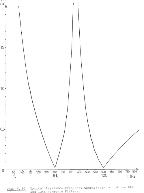
3.3.3 Harmonic Filters
3.3.4 Convertor Transformers 3.3.5 stor Valves
3.3.6 Predictive Controller 3.3.7 Transducers
3 A Individual Modules of the Convertor Model 3.4.1 AC Modules H
3.4 .1.1 Panel Design of Module H 3.4.1.2 Short Circuit Ratios SCR 3.4.1.3 Impedance Angle of AC
3.4.1.4 Impedance Characteristics of the AC System
3.4.2 Input/Output Module A-3 3.4.2.1 Design Features
48 48 48 48 49 49 51 53 53 54 56 56 59 61 61 63 63 63 66 66 67 72 72 3.4.2.2 Panel Design and Instructions 76 3.4.3 Angle Display Module
3.4.3.1 Features
3.4.3.2 Panel Design and 3.4 .4 Predictive Controller Modules
3.4.4.1 Features
3.4.4.2 Panel Design and
3.4 .5 Modules D
3.4.5.1 Design Features
B-3
C
i i i
3.4.5.2 Panel Design and Operating Instructions 87 3.4.5.3 AC voltage-waveforms and 87 3.4.6 By-pass Valve, Auxiliary Valve, and Transducers
Module E-3 90
3.4.6.1 Design Features 90
3.4.6.2 Panel Design and Operating Instructions 95 3.5 DC Transmission Line Modules
3.6 Fault Actuator
3.6.1 Design Features
3.6.2 Panel Design and Operating Instructions 3.6.3 Maximum Ratings and Fault Level
3.7 Overall Characteristics of the Convertor Model 3.8 Conclusions
4.1 Introduction
4.2 ON/OFF Detection of Convertor Valves 4.2.1 Introduction
4.2.2 Derivation of Conducting States from Current Detection
4.2.2.1 Experimental Results
4.2.3 Derivation of Conducting States from Voltage
95 95
98
100 100 102 102 105 105 105 105 106 108
Level Detection 110
4.2.3.1 Thyristor Firing Circuit 110 4.2.3.2 ON/OFF Level Detection 111 4.2.3.3 Logic Circuit for the ON/OFF Level
Detection 113
4.2.3.4 Experimental Results 114
.2.4 Prospective Applications of the ON/OFF Level
Detection 116
4.2.4.1 HVDC Thyristor Valves
4.2.4.2 Current-zero Detection in Industrial Convertors
4.2.5 Effects on Convertor Controllability 4.2 6 Conclusions
4.3 Direct Current and Voltage Measurement
116 118 119 119
Chapter 5 FAULT SIMULATION AND DATA ACQUISITION 5.1 Introduction
5.2 Normal HVDC Convertor Operations
5.2.1 HVDC System Representation for Analysis 5.2.2 Typical Rectifier and Inverter
5.2.3 Start-up
5.2.4 Power Reversal in Two-Terminal Systems 5.2.5 Shut-down
5.2.5.1 Sequential Convertor Shut-do\m 5.2.5.2 Fast Convertor Shut-down Based on
Conducting States of Valves 5.3 Classification of Faults
5.3.1 Introduction
5.3.2 Sequential Convertor Faults 5.3.2.1 Misfire
5.3.2.2 Firethrough
5.3.2.3 Commutation Failure 5.3.3 Consequential Inverter Faults
5.3.4 Internal AC/DC Short-Circuit Faults 5.3.5 AC Faults
5.3.6 DC Line Faults
5.4 Digital Fault Simulators Based on Hardwired Logic 5.4.1 Digital Fault Simulator
5.4.2 Design of Simple Fault Simulator 5.4.2.1 Main Design Features
5.4.2.2 Panel Design and Operating Instructions
5.4.3 Advantages and Limitations
5.5 Design Considerations of the Multimicroprocessor-based
1 21 121 122 122 122 126 129 129 129 132 138 138 139 139 146 149 159 166 169 169 170 170 172 172 172 177
Fault Simulation and Data Acquisition System 178 5.5.1 Design Requirements and Main Characteristics 178 5.5.2 Realization of the Multimicroprocessor-based
System 179
5.5.2.1 Selection of the Main System Components 179 5.5.2.2 Basic System Configuration and Function 181 5.5.2.3 Basic System Implementation and
Programming Languages 183
5.5.3 Main Design Features of the Fault Simulator 5.5.3.1 Basic Fault Simulator Design
5.5.3.2 Basic Fault Simulator Operation
v
5.5.4 Main Design Features of the Data Acquisition
Scheme 193
5.6 Hardware Design of the Multimicroprocessor-based Fault Simulation and Data Acquisition System 5.6.1 Realization of the Interrupt-driven
Multiple Microprocessor System
197
197 5.6.1.1 Overall System Configuration 19B 5.6.1.2 BOB5A-based Single Board Microcomputer
iSBC BO/30 202
5.6.2 Generation of Microprocessor Interrupts 5.6.3 Analogue-to-Digital Conversion
5.7 Software Design of the Multimicroprocessor-based Fault Simulation Scheme
5.7.1 VDU Terminal Manipulation Programme 5.7.1.1 Parameter Values Display 5.7.1.2 Numeric Values Specification 5.7.1.3 Character Selection
5.7.2 Interactive System Operation
5.7.2.1 Interactive Programme Selection 5.7.2.2 Process Controller Assignments 5.7.3 Main Fault Simulation Algorithm
5.7.3.1 Fault Simulation Service Routine 5.7.4 Fault Simulation and Monitoring
5.7.4.1 Fault Specification and Operating Instructions 203 206 20B 208 208 209 209 210 210 215 216 219 221 221 5.7.4.2 Repeating Modes of the Fault Simulation 227 5.7.4.3 Sequential Convertor Shut-down 228
5.7.4.4 Monitoring 230
5.8 Software Design of the Multimicroprocessor-based Data Acquisition Scheme
5.8.1 Convertor Operating-State Monitoring 5.B.l.l Normal Convertor Operating Modes 5.8.2 Data Acquisition under Normal and Abnormal
Convertor Operations
5.B.2.1 Memory Organization and Recording Principle
5.8.2.2 Fault-Data Recording Algorithm 5.8.2.3 Minimum Sampling Interval 5.8.2.4 Convertor Fault Recording 5.8.3 Display Facilities
5.9 Experimental Results 5.9.1 Introduction
5.9.2 Typical Test Results
5.9.2.1 Convertor Operating-State Monitoring and
P-INT1/P-INT2 Generation 245
5.9.2.2 Misfire Simulation 246
5.9.2.3 Firethrough Simulation 247
5.9.2.4 Commutation Failure Simulation 248 5.9.2.5 Sequential Convertor Shut-down 250 5.9.2.6 AC Fault Simulation and Fast Convertor
Shut-down 5.10 Conclusions
Chapter 6 POTENTIAL APPLICATIONS OF MICROPROCESSORS IN THE DETECTION AND PROTECTION OF HVDC CONVERTOR FAULTS 6.1 Introduction
6.2 Commutating Voltage Integral for Prevention of Initial Commutation Failures
6.3 Abnormal Convertor Operating Modes
6.3.1 Operating-Mode Declaration Routine 6.3.2 Typical Test Result
6.4 Severity Assessment of Convertor Faults for the Fast Convertor Shut-down
250 258
260 260
261
263 263 266
267 6.4.1 Fault-Severity Assessment Routine 267 6.4.2 Typical Test Result - Fault Event. Limit 270 6.4.3 Typical Test Results - Double Successive Fault 272
6.5 Conclusions 276
Chapter 7 CONCLUSIONS 277
REFERENCES 279
APPENDIX Al MEMORY MAP OF THE MULTIMICROPROCESSOR-BASED FAULT SIMULA'1'ION AND DATA ACQUISI'!'ION SYSTEM
APPENDIX A2 INTERRUPT SERVICE ROUTINE P-INTO APPENDIX A3 INTERRUPT SERVICE ROU'1'INE I-INT65
Vll
LIST OF PRINCIPAL SYMBOLS
'l'he majority of symbols are defined as they appear in the text, and a comprehensive system of scripting is used for clarityo For convenience the principal symbols are redefined below.
Symbols A
A. l
A. ,ADR.
l l
AB. l BLK. l C ci C, l Ck CF. , 2
l , l +
CLR.
l
CS.
l
Di D. r DAT.
l l
E
E m
EA., c5
l l
EDDC FP. c FT. l G G. l
Variable Gain of Error Signal Generator Anode of Convertor Valve V.
l
Address Bus Bit i (i
=
0 to 15)Arcback (Backfire) of Convertor Valve V.
l
"Low" to Block FP.
l
Capacitance Capacitor i
Commutating-voltage-zero Crossing Instant (i (in the Figures Ci)
Clock Pulse
1 to 6)
Commutation Failurer ioeo Failure to Commutate Current from Valve V. to Valve V. 2
l l+
"Low" to Clear FP.
l
Chip-Select Signal of Integrated Circuit i (Active-Low) Diode i
Data Bus Bit i (i
=
0 to 7)Root-mean-square (rOm"so) Value of Commutating Voltage Crest Value of Line-to-Neutral Voltage of an AC System, Normally
/3
E /2Em
Extinction Angle of Convertor Valve V. (i
l
"Low" to Enable Direct Digital Control
1 to 6)
Firing Pulses to Valve Gates Gl to G8 (Normally about 120 degrees of Duration for Valve VI to V
6) Firethrough of Convertor Valve V,
l
Ground Potential
Gate (or Grid) of Convertor Valve V,
l
rci
I-INTn Ki L LEDi MF. l N ON. l P-INTn Q Q R R Ri R, Y, B RD RSTn S S. lswi
TConstant Current Control Setting (Direct Current Reference)
Direct Current Margin Integrated Circuit i
Interrupt Service Routine Level n of Interactive Controller
Convertor Control-System Constant Cathode of Convertor Valve V.
l
Inductance in General
Leakage Inductance (Commutating Reactance WL) per Phase of Convertor Transformer
DC Blocking Reactor
DC Smoothing Reactor or its Inductance Light Emitting Diode i
Misfire of Convertor Valve V.
l
AC-System Neutral
ON/OFF (Conducting or Non-Conducting) State of Convertor Valve V.
l
Instant of Start of Conduction of Convertor Valve V. l
Firing Instant Correction
Interrupt Service Routine Level n of Process Controller Normally, "Low" to Fire Convertor Valve V.
l
Factor of Filter
Output State "High" or "Low" "High" to Reset Flip-Flop
Resistance Resistor i
Red, Yellow and Blue Phases of an AC System to a, b, and c Phases)
Generalized Memory/Port Read Strobe (Active-Low) Level n
" to Set Flip-Flop
Instant of End of Conduction of Convertor Valve V, L
Combined CC and CEA Output for Valve V. Firing in
Predictive Controller l
Switch i
TH. l TRi TRG V c V. l i VRi WR
x
Z ZDia
or MDA
6
o
or CEA or EAi
)
.
]
Initiation of Conduction of Convertor Valve (i 1 to 6, Timing Pulses of Short Duration) Thyristor Valves Numbered from I to 6 Referr Firing Sequence; also By-pass and Auxil and THS in the Convertor Model,
Transistor i
to
Trigger Pulse Output to Fault Recording Instrument(s) Control Voltage of Analogue-type HVDC Control tern Direct Line Voltage of Convertor
Direct Line Voltage of Inverter
Nominal Direct Line Voltage of Convertor
Ideal No-Load Direct Line voltage of Convertor Direct Line Voltage of Rectifier
6-pulse Bridge Valves Numbered from 1 to 6
to Firing Sequence (Mercury-arc or Thyristor Valves) By-pass Valve (Mercury-arc Valve)
variable Resistor or Potentiometer i
Generalized Memory/Port Write Strobe (Active-Low) Reactance
Impedance Zener Diode i
Convertor Firing Delay Angle
Preset Minimum Delay Angle on MDA Control Delay Angle of Convertor Valve V.
l
Preset Constant Extinction Angle on CEA Control Extinction Angle of Convertor Valve Vi, i.e. Angle between the End of Commutation (Sil, and Respective Commutating-voltage-zero Crossing C. I
l
-Minimum Extinction Angle
0
per Cycle j prior to Valve V. Fil
Preset Optimum Extinction Angle
0
on MEA Control Rate of Change of Direct Current IdCurrent Error Signal, i.e. A(I - Id }
e , a e ,
ac f f o i. 1 j If r t u v a vd v. 1 V n V p W W 0
r
I
,
a >
a <
0 x % Vb' b b V
units and A
AC, a.c 0
A/D, D/A c
Instantaneous AC-System a, b, and c)
to Neutral (Phases
Commutating AC-System Voltages (Phase a to Phase c, etc.) Frequency in General or AC-System
Nominal AC-System Frequency, 50 (or 60) Hz Impedance Angle of an AC-System
Instantaneous AC-Line Currents (Phases a, b, and c) Commutating Current
Instantaneous Current of Valve V. 1
,2 -1
J
3.14159 or equivalent to 180 electric Resistance of Windings
Time
Convertor Overlap Angle
Convertor Voltages to Neutral (Phases a, b, and c)
Direct Voltage of Convertor
Instantaneous Anode-to-Cathode Voltage of Convertor Valve
Direct Voltage with respect to Convertor Transformer NeutralN
Positive Direct Voltage with respect to Convertor Transformer Neutral
Angular Frequency, i.e. 2nf
Nominal AC-System Angular Frequency, i.e. 2TIf o Root
"a" greater than lib" "a" less than "bl!
"x" in electric degrees per cent
ampere
Current
ASCII ASEA ASM BCD CB CC CEA CPU CT
DCI d.c.
DCT DDC EA EPROM F FS GEC German-Swiss HVDC H Hi HP HVDC Hz IC lEE IEEE INT Inv IOC ISC K Lo LSB IO
American Standard Code for Information Allmanna Svenska Electriska
Sweden
Assembly Language Binary-Coded Decimal
Unit of 8 Binary Digits (Bits) Circuit Breaker
, Ludvika,
Constant Current of Convertor as CC Control
xi
Constant Extinction Angle of Convertor as CEA Control International Conference on Large
Electrical Systems, Paris, France Central Processing Unit
Current Transformer(s) Direct Current
Differentiating Current Transformer Direct Digital Control
Extinction Angle of Convertor as EA Control Erasable Programmable Read-Only Memory Filter (s)
Fault Simulation
General Electric Company, Stafford,
Group Organized by AEG-Telefunken, Siemens, and Brown, Boveri & Cie., West Germany and Switzerland
henry
Logic State "High"
High-Pass (Filter)
High Voltage Direct Current hertz
Integrated Circuit
Institution of Electrical I London, England
Institute of Electrical and Electronic New York, U.S.A.
Interrupt or Interrupt Service Routine Inverter
Input/Output
Inverter Optimum Control Inverter Safety Control 210
=
1024, unit of Memory Logic State "Low"·MDA MEA MSB MW NoZo rl
P-A, Pre-Amp PIC
PIT
PL/~1, PLM
PPI PT RAM Rec ROM SCR TTL UMIST USART
v
VDU W 11111111BOOH to FFH
cos dB h i kVA mm ms n nF ns
Minimum Delay Angle of Convertor as MDA Control Minimum Extinction Angle of Convertor as MEA Cont,-ol Most Significant Bit or Byte (8 Bits)
6
megawatt (10 watt) New Zealand
ohm
Pre-Amplifier
Programmable Interrupt Controller Programmable Interval Timer
High-Level Programming Language Similar to PL/l Modified for Intel's Microprocessors
Programmable Peripheral Interface Potential Transformer(s)
Random-Access (Read-Write) Memory Rectifier
Read-Only Memory Short Circuit Ratio
Transistor-Transistor Logic
University of Manchester Institute of Science and Technology, England
universal Synchronous/Asynchronous Receiver/Transmitter volt
Visual Display unit watt
8-bit Binary Number, Equivalent to 255
8-bit Hexadecimal Numbers, Equivalent to 0 to 255
cosine
-1
decibel (10 bel.) hour
Inverter (Subscript)
. ( 3 . )
kllovolt-ampere 10 volt-ampere
. . (10- 3 )
mllllmetre metre millisecond
Nominal (Subscript) -9
r
r.m.s. , rms
sin tan WF ws
xiii
picofarad (10 -12 farad) Rectifier (Subscript) Root Mean Square second
sine tangent
microfarad (10-6 farad) microsecond
Source of Electromotive Force
Earth
Three-phase Star (or Wye, y) Transformer Connection
Three-phase Delta (~) Transformer Connection
Three-phase Two-winding Convertor Transformer with Tap Changer for 6-pulse Operation
AC Harmonic Filters Bank(s)
Convertor Valve in General or Conducting Valve
Non-Conducting Valve
Incoming Valve (being fired)
Outgoing Valve (to be extinguished)
6-pulse Graetz Bridge
Isolator or Disconnector (Switch)
Transistor (NPN)
Diode
Zener Diode
Resistor
-II--
CapacitorInductor
Direct Voltage Source
Ground Potential
Operational Amplifier (Op.-Amp.)
Positive AND Gate
Positive (Inclusive) OR Gate
Inverter Gate
Integrated Circuit (IC) with Specified Function
1 mm or 2 mm Socket
xv
ABSTRACT
Aimed at the eventual implementation of direct digital control and tion in a.c./d.c. power systems, this thesis describes the
a stor convertor model and an interrupt-driven mul
system of simulating various faults encountered in real and of moni
real time
the normal and abnormal convertor operating states in
Recent developments of HYDC convertor control and are of
first reviewed, and a fast and reliable method of deriving convertor-valve ON/OFF states is practically implemented in the model and assessed for
other s.
A comprehensive set of normal and abnormal convertor waveforms is derived and used as a basis for the software-based fault simulation and fault-data ition scheme. The proposed scheme takes full of
the versatile and cost-effective general-purpose microprocessor to provide sophisticated convertor operating-state monitoring, fault data
and immediate display on the inter-connected VDU terminal.
ACKNOWLEDGEMENTS
I am cordially grateful to my supervisor, Professor Jo Arrlllaga, for his assistance, encouragement and warm friendship throughout this research.
I also acknowledge the value of the many stimulating discussions with and generous assistance from my Power Systems colleagues, in
particular M. 80 Dewe, C. P. Arnold, Co 80 Lake, Mo I. Parr, 8. J. Harker, K. S. Turner, M. D. Heffernan, and J. C. Graham. My \vholehearted gratitude goes to the technical staff who provided the precious skills such as mlmlC engravlng and transformer winding.
Special recognition is due to New Zealand Electricity and the University Grants Committee for their financial assistance required for conducting this research.
CHAPTER 1
INTRODUCTION
The number and sophistication of a.c./d.c. simulators have increased in recent years. Their development is costing millions of dollars and their use and maintenance require experienced s. (1-5 )
In the author's opinion such expensive facilities do not provide the answer to the modelling problem.
The Power Systems group at the University of Can has been the behaviour of a.c./d.c. power for the
several years. The main emphasis has been on computer models rather than simulators on the basis that sooner or later computer software will
the hardware models as i t did in the case of the network analyzer in the previous two decades. A large measure of success has been
h ' d ' h' (6-8)
ac leve 1n t 1S respect.
However, i t is recognised that there are certain areas where the use of computer modelling is very limited, e.g. control stabili , real-time control and protection, and in such cases there is a need for a restricted purpose scaled-down model. For the specific complementary purposes indicated, i.e. investigations on high vol direct current
(HVDC) control and protection, the model should be flexible to accommodate alternative schemes based on conventional and new ideas as well as
A scaled-do\ro model is indispensable to demonstrate itatively the behaviour of HVDC links. In this respect i t is to provide sufficient monitoring points and switches to show the effect of each plant component. The design of the basic convertor for transmission line models is discussed in Chapter 3.
Con the high level of information available at the convertor , the eventual implementation of direct digital control and protection
h d b '1 d (9-11). d f ' ,
suc as propose y Arrl laga an Galanos, lS a e lnlte It is realised that such developments are ly restricted by the unavailability of sufficiently accurate and fast transducers and Chapter 4 concentrates in this area with particular emphasis on the
of valve ON/OFF information.
5 deals with fault simUlation and data acquisition
facilities. A comprehensive fault simulation scheme is needed of subjecting the a.c./d.c. system to the various faults encountered in practice with t-on-wave control of the instant of fault application, valves involved and their duration, etc. In order to exact
diagnosis of convertor behaviour, the model should be provided with fast data acquisition scheme capable of storing sequential valve ON/OFF infor-mation, direct current and voltage, control angles, etc. A versatile graphic di ay facility is also indispensable to present the recorded data for
Based on the fault simulation scheme described in Chapter 5, some examples are demonstrated in Chapter 6 to illustrate the potential application of the microprocessor-based system to the detection and protection of HVDC convertor faults.
3
CHAPTER 2
GENERAL REVIEW OF HVDC CONVERTOR
2.1 TRENDS IN HVDC APPLICATIONS
Ever since high voltage direct current (HVDC) transmission of electric power first became a commercial reality with static convertors in 1954, (13) HVDC systems have been progressively to various transmission schemes for a variety of reasons where transmission distances from to load centres exist (e.g.
U.S.S.R. 1962, and Nelson River, Canada 1975); where ties are or preferred (e.g. Sakuma Frequency Changer, 1965, and Cross-Channel, England-France 1961); where underground or underwater cables of considerable length are necessary (e.g. Kingsnorth,
1975, and New Zealand 1965, respectively). Over the last two decades, the characteristics of HVDC schemes have proved
desirable over alternatives, and/or economical
with conventional extra high voltage a.c. (EHVAC) transmission. until the early 1970's all HVDC schemes utilized mercury-arc valves in the a.c./d.c. conversion process. However, the commercial appearance of silicon-controlled rectifiers (SCR) or in 1957, an intensive development of the high-voltage and
for HVDC took place in the late 1960's. The
first commercial of thyrlstor valves (Gotland, Sweden 1970 . (14) ) and convertor stations (Eel Rlver, Canada 1972 . (15) ) were
success achieved. Technological developments of and in b capabilities against reverse voltage have not only the mercury-arc valves, but also provided higher
designers. The practical voltage and current ratings for a specific ffiTDC power scheme can only be determined by an optimal study involving the convertors and other related technology, e.g. convertor transformers, transmission cables, etc.
In the last decade bipolar ffiTDC schemes with power capacities between 1,000 MW and 2,000 MW have been constructed, and the bipolar power capability of 2,500 to 4,000 MW (±600 kV, and 2,100 to 3,300 A) is
(16)
currently available with thyristor valves. In addition to the upgrading of thyristor valves and hence the practical power ratings of ffiTDC schemes, the size and relative cost of convertor stations have
(17,18) dropped in general, due to innovations in design concepts.
The reliable operation of ffiTDC convertors is of prime importance under various a.c./d.c.-system conditions, especially as the amount of electric power transmitted by HVDC is becoming relatively larger and the a.c. systems becoming "weaker". Various disturbances in the a.c./doco system can lead to maloperation of ffiTDC convertors, e.g. commutation failures of the inverter.
Due to the interaction which exists between ffiTDC control and protection, fast diagnosis of HVDC convertor disturbances is of great importance for rapid adjustment of control, and correct measure of
, (11)
overall protectIon. The growing acceptability of ffiTDC transmission h as b een enhance d b y Its ' a b ' l " I Ity to Increase system re Ia I' b ' l ' t 1 I y, (19) to
" (20) " (21)
5
2.2 BASIC CONVERTOR-STATION CONFIGURATIONS
2.2.1 Introduction
The three phase convertor which has found universal ance in HVDC schemes is the 6-pulse Graetz bridge and early schemes
individual operation during a period of emergency transmission at half a rated power, where two 6-pulse bridges are normally connected in series on the d.c. side to provide 12-pulse operation (double-series
6 se convertors to be described in Section 2.2.2.2). In recent HVDC schemes with thyristor valves, two 6-pulse bridges form a se convertor unit which simplifies a.c./d.c. main circuits and eliminates the of 5th and 7th harmonic filters on the a.c. side of the convertor.
The of these convertors and two-terminal is well
. . . . 196 (22)
documented In Ilterature by Adamson and Hlngoranl 0, Cory ed.
(46) . (47) (48)
1965, Klmbark 1971, and Uhlmann 1975. A concise
about the present state of the art in the control of two-terminal HVDC
. ' . . (49)
systems lS presented by CIGRE's study Commlttee No. 14 (DC Llnks) 1978.
. . h 1 1 d (50-55)
2.2.2 Convertor-station Configurations
2.2.2.1 Single 6-pulse Convertor. Fig. 2.1 schematical illustrates a typical 6-pulse convertor which consists of a
I a d.c. smoothing reactor, a three-phase two-winding convertor
t.ransformer, an a.c. circuit breaker, and a.c. harmonic filters as the main components. In order to provide safe maintenance work a.c./d.c.
switches are used to disconnect the valve group, as shown in 2.1a. Various earthing switches (not shown in Fig. 2.1) are also
to ground these main components.
In most HVDC schemes commissioned before early 1970's mercury-arc valves are used. These are prone to stochastic arcbacks (i.e. abnormal reverse conduction of a valve) due to rise of direct current or valve
(46,48)
, and/or overvoltages. In order primarily to protect the main valves from the overcurrent caused by the arcback in the
rectifier, a seventh valve or by-pass valve V
7 is provided as shown in 2.1a, which takes over the bridge current when the main valves are blocked. In association with the by-pass valve is the by-pass switch. This is closed when longer or permanent bridge-blocking is required, or i t is when the convertor bridge takes over the direct current via the s valve.
With automatic selection of the by-pass pair formed by the main valves , V
3-V6' or VS-V2' however, i t has been proposed that the valve can be eliminated under nor~al and abnormal convertor d" (56)
can ltlons. Because thyristor valves do not have the arcback
, the by-pass valve is not required in recent HVDC convertors, where valves are installed. In such cases, one of the three
is automatically selected for blocking/deblocking the
The d.c. smoothing reactor L
(a)
( b)
Convertor
Convertor
Busbars
Transformer
a be
AC Circuit
Breaker(CB)
6-
eBridge
7
By-pass
Switch
AC Isolating
.Swi tches
DC Isolating
Switches
- - - - ---l
i
RYB
I
II
F
5th,7th,11th,
th Harmonic and
High-pass(HP) Filters per Phase
Convertor
Busbar
CB
Convertor
Transformer
6-pulse
Bri
...
-~-X----Iy y
5th,7tt
llth,13th
HP Filter
Single 6-puls8 Convertor:
(a) Main AC/DC Circuit,
DC Isolating
Swi tches
Ilne. Its main purposes are to ensure a continuity of the direct
current with reduced current ripples, and to limit the rate of increase of direct current during commutation in one bridge when the direct
voltage of another inverter bridge collapses due to commutation failures. The crest current in the rectifier due to a short circuit on the d.c. line is also limited by the reactor.
As shown in Fig. 2.1 a circuit breaker is required for clearing faults in the transformer or flashover faults ln the bridge, or for taking the whole d.c. link out of service.
2.2.2.2 Double-Series 6-pulse Convertors. Most of HVDC
convertors normally perform 12-pulse operation. A simple configuration which realizes such 12-pulse operation consists of two single 6-pulse convertors connected in series on the d.c. side, but in parallel on the a.c. side of the convertor transformers, as illustrated in Fig. 2.2.
Convertor
Busbar
Convertor
6-pulse
Transformers Bridges
CB1
...----X - - - - {
C82
...---- X ---(
y~
y y
F
5th,7th
llth,13 t h
HP Filters
DC Isolating
Switches
Fig. 2. 2 Double-Series 6-pulse Convertors:
DC Line
By-pass
Switch 1
By-pass
Swi tch 2
Electrode
Line
[image:26.561.58.510.443.739.2]9
a testing period before commercial commissioning, with a minor modification of switching arrangement on the d.c. side, back-to-back connected convertors are formed by the 6-pulse convertors, viz. , one convertor rectifies the alternating power and the other inverts the rectified direct power back to the same a.c. system and the direct current flows through the smoothing reactor L
d. This is one of t.he standard configurations of HVDC convertors before the d.c. lines and other convertor stations are involved for further tests.
2.2.2.3 Unit 12-pulse Convertor. The unit of 12 (57)
illustrated in Fig. 2.3, is becoming standard for as
HVDC ications. In this configuration the convertor station is
fied by the absence of by-pass and d.c. switches which are required for 6-pulse operation. The a.c. circuit breaker is
common to the two bridges and the 5th and 7th harmonic filters are eliminated.
Convertor
Busbar
Convertor
6-pulse
Transformers
Bridges
DC Line
Y fl
Y Y
llth,13th
HP Filters
. 2.3 unit 12-pulse Convertor:
12-pulse Convertor which is as a Unit.
Referring to Fig. 2.3, the d.c. smoothing reactor Ld 1S transferred to the ground side of bridge 2, so that overcurrents of conducting valves due to ground (flashover) faults in the bridges or at
h . (48,57)
t e d.c. term1nals can be reduced. This arrangement also allows the inSUlation requirement on the reactor to be reduced, however, an additional small d.c. blocking reactor Lb is still required to protect the valves from steeep overvoltages which are caused by travelling waves from the d.c. line and switching operations in the d.c. switchyard.
(48) ,
The inductance of ~ is normally about 5 to 10 mH and pract1cally, an air-cored reactor may be installed near the d.c.-line terminal of
, (57)
bridge 1 as shown in F1g. 2.3. A similar arrangement of the
reactors is also applicable to the previous configuration shown in Fig. 2.2, but a blocking reactor Lb must be provided for each valve group.
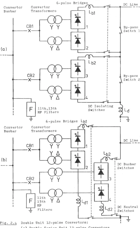
2.2.2.4 Multibridge Convertors. From an HVDC system-designer's point of view, the use of single 12-pulse convertor per pole (Figs. 2.2 and 2.3) for the required full transmission capacity is the easiest solution since the switchyards, on both the a.c. and d.c. sides, will be therefore greatly simplified. Thyristor convertors with 12-pulse ratings of 480 MW (Cabora Bassa-Apollo, South Africa 1977) r 560 MW (Inga-Shaba,
Zaire 1977) and 500 MW (Nelson River Bipole-two, Canada 1978) are already operating and there is a demand for ratings of 1000 MW to 1500 MW per
(16)
12-pulse convertor. However, as convertor ratings increase,
transportation limitations for convertor transformers, i.e. their weight and size, vlill often determine convertor station configurations. One method to cope with the transportation limitations may be to install three single-phase three-winding transformers or even six single-phase two-winding transformers instead of the two three-phase two-winding
, 2 2 2 3 (16) trans formers of F 19S . . and . .
lJ
series or on the d.c. side at reduced ratings per 12 se convertor, as illustrated in Fig. 2.4. These configurations also enable
developments of HVDC schemes which are sometimes desirable, for , when large-scale hydroelectric generators are continually
over years. Referring to Fig. 2.4a, double-series unit 12 se convertors can be developed in stages such as the Nelson River
scheme except with conventional installation of
, (58)
reactors on the d.c.-line slde. In this case conventional control is applicable. Double-series 6-pulse convertors (F . 2.2) can be also developed in stages to form multibridge
(quadruple-series 6-pulse convertors), e.g. Cabora Bassa 10 scheme. ( 3) For mercury-arc valves where the practical maximum are 133 kV . to 150 kV (59) , trlp e-serles .-pu se convertors per ' 1 ' 6 1 are not uncommon, High transmission voltages of ±400 kV for the Pacific
Intertie, U.S.A. 19701 and ±450 kV for the Nelson River
Canada 1972, can thus be achieved.
The relative merits of the series and parallel of unit 12-pulse convertors depend on the HVDC (5) In the parallel configuration of Fig. 2.4b, the reactor is
for each 12-pulse convertor and a current-balancing control is necessary for both rectifiers and inverters mutually connected in
When HVDC schemes are developed in several stages over years and long overhead transmission lines are used in rural areas where both convertor stations are normally provided with earth as shown in . 2.4b and electrolytic corrosion of buried or immersed metalic structures due to ground currents can be made (47) the
parallel configuration provides less line losses during the period when full line currents are not established, e.g. sc eme lD Zalre. h . ' (5) In this schemel ohmic (resistive) line losses have been found more
Convertor
Busbar
Convertor
Transformers
(0 )
CB1
... - - X
CB2
.-.--- X---e
y y
Yl1
y y
Y l1
llth,13th
HP Filters
1
6-pulse Bridges
Lb1
Convertor
Busbar
Convertor
Transformers
(b)
CB1
o---x
CB2
Y Y
Y
~
Y Y
Fig. 2.4 Double Unit l2-pulse Convertors:
I
I
I
I
I
I
I
I
I i I
I
I
I
I
I(a) Double-Series Unit l2-pulse Convertors,
(b) Double-Parallel Unit l2-pulse Convertors.
By-pass
Switch
By-~
Swi tch 2
DC e
DC Busbar
Switches
[image:30.563.69.516.47.773.2]13
scheduled.
Fol permanent d.c. line faults, bipolar overhead line schemes can be so that two d.c.-line terminals (station poles) are
paralleled to operate in monopolar mode, where the line is with ground return, e.g. Cabora 10 ( 3) and
R' (58)
Nelson lver schemes. In this case the requirements for
(5) should be fulfilled during the temporary period. The
transmission line should be also able to carry the excess direct current for a desired time. (When the current is doubled, the ohmic line loss becomes four times bigger.)
2.2.2.5 Some Design. Aspects to Unit 12-pule Convertor. In
of the economic considerations made for higher direct and current (16,19,48) and the h' h 19 er avallablllty of transmltte " . . d power, t e h
limitations of present HVDC technology such as d.c. cables 500 kV (1,000 A) or 600 kV (850 A) (60-65) and environmental
up to
(17-19,66) 1
may a so introduce some restrictions on convertor-station configurations. For instance, a proposed new 2,000 MW Cross-Channel HVDC Link (England-France, December 1984 for commission
two links of the bipolar unit 12-pulse convertors which are similar to 2.3 except with conventional installation of smoothing reactors on the d.c.-line side, rather than the configuration described in Section 2.2.2.4. Eight d.c. cables rated at 270 kV and
to the unit concept of 12-pulse convertors, fresh
consideration has been given to exclusively apply a.c.
~'lt
f th d C h i L' k (67) h£1 ers or e propose ross-C anne HVDC 1n. T ese a and maintenance requirements.
A concise review of the d.c. harmonic filters (damper circuits) (68)
on various HVDC schemes is given by a CIGRE report. With to the unit concept of 12-pulse convertors, smaller
reactors and simpler d.c. filters may be expected in future HVDC schemes. Back-to-back connected convertors and 12-pulse are
ied to frequency changer, e.g. Shin-Shinano
1977, (69) and to asynchronous interties between different power authorities, e.g. the USSR-Finland HVDC Intertie, where three
s of unit 12-pulse convertors are to be connected back-to-back
(70)
between the two a.c. systems.
2.3 BASIC CONTROLS
2.3.1 Introduction
15
In order to achieve reliable operation of HVDC convertors, maximum and minimum direct current and voltage limits are normally
with the basic controls, and during the disturbances lated firing-angle controls are transiently
for both rectifier and inverter operations of HVDC convertors.
A weak a.c. system with very light damping is a very severe system
condition and controllability of the extinction angle of inverter is of , since inverters are the most susceptible to transient disturbances in the a.c./d.c. system.
There are two different basic methods for the extinction angle control, i.e. firing to achieve the desired extinction and closed-loop control of the extinction angle actually measured. Moreover, the advantage of symmetrical or equidistant firing-angle control techniques over the basic predictive (individual phase) control
. (23)
for HVDC convertors are by now well establlshed. In particular, a considerable reduction of the abnormal harmonic content of the a.c.
(orders other than 5th, 7th, 11th, 13th, etc. for a three-convertor) can be obtained, which results in more stable operation.
2.3.2 Individual Phase Control
2.3.2.1 Predictive Control. For basic control the individual angles are calculated using the convertor
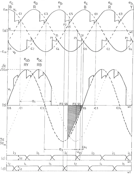
voltages and currents up to the instant of firing of each valve. The control is directly phase-locked to the a.c. system in both magnitude and , and under steady state conditions with balanced a.c. sinusoidal voltage-waveforms, the resultant extinction angle is constant for each valve. The relationship governing the commutation process relies on the fact that the time of the commutating , i.e. yoltage integral, is equal to the overall
produced by the commutating current With reference to . 2.5, the relationship can be expressed as:
E sin (wt) dwt
where
a
is the firing delay angle,<5 is the preset constant extinction angle (CEA) , c
E is the r .m.s. value of the commutating voltage, w is the a.c. system angular frequency,
L is the inductance per phase of the convertor transformer (assumed constant)
is the direct line current.
Thus the for the predictive constant extinction (CEA) control is:
E cos [j., +
12
E cos <5 c(2.1)
(2.2)
17
Em
I \ I \ I I \
(al~N~,--+-~_----+-~~~---~--~~---+--~~----~---I \-Em
(bl~---~---~--~---~~~----~---~~-w~t
C6 oC1 C3 \ ·C1 C3\
-.f2E
-13
E.
\
\\ \
\ \
\ \
\
\
\ I \
\ I \
\
\
I
\
\ I
' \ . . / 0
'-
""
~ ..~--
a3 _ ..
---;~-*-I-15
h
Typical
6-
e Inverter under predi tive Constant Extinc-tion e (CEA) Control:(a) Positive and ive Dtrect Vol wi th res pee t to the Transformer Neutral,
(b) Voltage across Valve 1, and Commutating Voltages, ec) Valve Current iI, i3, and i5'
i6-in F . 2.5 is directly proportional to the direct current In
relation to the variables E, 00, and Id in equation 2.2, the delay angle
a
can be computed so that the desired constant extinctioncan be maintained. since the frequency deviation of an a.c. is norma small, the commutation reactance ooL is constant. However, 2.2 provides the phase-locking characteristic even
with a.c. variations.
With to the direct current Id rising during the commutation process due to a.c./d.c.-system disturbances, the current at the end of commutation will be larger than that anticipated by the CEA controller. Hence, compensation must be made for the rate of rise of direct current, i.e.
dt , so that the firing occurs at a correspondingly earlier instant. Assuming a steady increase of current the
commutating 2.2 becomes:
E cos
a
+/2
E cos 6c 200L (Id + u. dId) dlJJt (2 .3)
In there is a normal maximum value of u as used in equation 2.3.(24) A for the rate of change of direct current can provide a fast in response by measuring the voltage induced across the reactor or the d.c. transductor coupled with d.c. busbar.
With re to previous Fig. 2.5, however, i t should be noted that the vol actually governing the extinction angle of outgoing valve is that of the previous valve; e.g. the commutating voltage (RB) is used to compute equation 2.2 for the valve VI' and its extinction is determined by the commutating voltage e
19
four extinction angles in 6-pulse bridge.)
Although the convertor firings are independently computed for the fast response to system change, non-symmetrical firings are caused by unbalanced and distorted a.c. voltages, a common phenomena with weak a.c. systems. This is because the accuracy and predictive ability of the control is closely related to the validity of the assumptions made in the development of the mathematical expression of the commutation process. Moreover, any inaccuracy in the firing instants of the valves generates uncharacteristic harmonic currents in the a.c. system, which can lead to
h h ' f d' " '1' f h (23)
t e armonlC wave orm- lstortlon lnstabl lty 0 t e HVDC system.
Any secondary d.c. components of convertor transformer caused by firing-angle unbalance will cause additional zero-sequence primary-current
components which contain higher harmonics owing to transformer-saturation effects. Installation of a.c. main harmonic and/or control system
filters can reduce this problem, but not remove it.
By measurement of the direct current and the integration (i.e. 900 phase shift) of the appropriate valve-commutating voltages, the correct
, (22,24-27)
firing angle for the predictive CEA control can be achleved.
From the first commercial appl~cation of HVDC transmission, i.e. Gotland
h ' 1 54 ( 1 2 ) . 97 I 1 h h . . d
sc erne ln . 9 , untll early l O s , al t e HVDC sc emes commlSSlone were based on the principle of predictive CEA control.
Chapter 3 describes a practical design of the control which combines the constant current (CC) control and minimum delay angle (MDA) control. For the CC control, a so-called lnverse-COSlne control . . (23) , J.S
(24 27)
implemented, and a constant delay angle can be set manually. (
2.3.2.2 Closed-loop CEA Control. In order to prevent commutation failures in an inverter, an early closed-loop control of extinction
(28)
voltage per valve and the respective commutating-voltage-zero crossing. In order to derive the control signal, i.e. extinction-angle error,
o
each extinction angle measured at about 60 intervals is successively converted to a voltage level by an integrator, and its output compared with the direct voltage representative of the CEA setting.
During a transient period of a.c.-system voltage reduction, the detection-correction circuit is assigned to increase the CEA setting so that the probability of commutation failure can be reduced. However, because of the analogue circuitry applied and the smoothing time-constant lags either in the feedback loops or control system filters, the
proposed CEA control is unrealistically slow in response, e.g. a new extinction angle can not be achieved until about 0.5 second after the correction of CEA setting.
According to a similar principle, a refined closed-loop CEA
. (29)
control has been independently proposed by the German-Swlss HVDC Group, (30) and its dynamic behaviour has been tested on an HVDC model plant. In this scheme two integrators are separately applied to convert the extinction angles measured on both sides of a 6-pulse bridge, and at about 600 intervals the greater value of either previous or present deviation from the CEA setting is selected and held to obtain the error
. (31)
slgnal. Triple gains are introduced to scale the angular adjustment, so that the smaller the measured extinction angle is, the larger will be the reduction of firing delay angle. In order also to achieve a faster
. ' . ( dId) .
closed-loop CEA control, a rate of rlse of dlrect current ---d ' lS t
21
1S still limited by smoothing time-constant lags.
Since then the same German-Swiss HVDC Group has proposed a
1 d l . . l ' . (32,33)
c ose - oop extlnctlon-ang e-palr contro~. In this proposal, three relatively independent extinction-angIe-pairs (i.e. 01 and 04'
(Three control loops refer to the common CEA setting.) This modified closed-loop CEA control can in the steady state provide better characteristic of harmonic
stability over the previous closed-loop CEA control; however, during and after a.c.-system disturbances, considerable amounts of normal and
abnormal harmonic-current contents in the a.c. system are observed. This is because d.c. components superimposed on the a.c. voltage cause asymmetry of the positive and negative half-cycles of the a.c.-system voltages which are in the steady state assumed nearly symmetrical. With increased reduction of single-phase a.c.-system voltage, considerable magnitudes of 3rd and 9th harmonic currents are observed in the a.c. system, which is highly undesirable especially when the a.c. system has a resonant frequency close to these harmonic frequencies, e.g.
Cross-(12,23) Channel and New Zealand HVDC schemes.
Although the direct measurement of extinction angle and its
implementation to the control loop is technically valid, the closed-loop CEA control alone will be only applicable to relatively strong a.c. systems. This is primarily due to the nature of individual or asymmetrical phase control as mentioned in Section 2.3.2.1.
However, for the sake of minimum reactive power consump·tion in (6,34)
without altering the hardware devised. In this case the digital closed-loop CEA control mode may have to contain a detective-corrective
iterative process per extinction angle, such as the one to be described in Section 2.3.4.3. Moreover, a predictive adjustment of firing delay angle should be also incorporated, so that commutation failures in an inverter may be prevented or at least the recovery made as quickly as possible.
2.3.3. Equidistant Control
2.3.3.1. Ainsworth's Phase-locked Oscillator Control System. Equidistant control features equally spaced firing pulses in steady state, i.e., each valve receives a firing pulse 600 after the previous firing. The first practical application to the Kingsnorth and Nelson River Bipole-one HVDC schemes (GEC, England 1975) utilized a voltage controlled oscillator (VCO) and a ring counter as the main components
. . 1 (35)
for equldlstant contro . Fig. 2.6 shows the principle of Ainsworth's phase-locked oscillator control system which implements constant current
(CC) and minimum extinction angle (MEA) controls.
The output of the oscillator is a train of short pulses at a pulse repetition frequency f
l , such that f 1 = k V , where k is the c oscillator constant and V is the oscillator control voltage. The
c
6-stage ring counter changes by one step per input pulse, each
transition sequentially producing the firing pulse to a valve gate or grid. In the steady state condition, Vc is such that fl
=
6 ff where f is the a.c.-system frequency. Thus each valve receives a firing pulse 600 after the previous firing. In practice the independent oscillator described would drift in frequency and phase relative to the a.c. system. Hence, the control voltage V is derived from a negativec
phase-AC System
H V DC Convertor
f
Convertor Busbar
Convertor Trans former
Commutating Vol s
AC PT
Vo ross Valves
Control
Ids
Direct Curren t SettA
Extinction Angle Me I'
eab
I'--I---=;;M C i I'
Per Val
v
EA1
EA2
EA3
EAt.
EA5
EA6
DC CT
Direct Current Measuring Cireui
Voltage Controlled Oscillator
6-stage Ring
Counter
1
2
3
Conv rtor
Fir
ng PuPrinct System:
of Ainsworth's Phase locked Oscillator Control Equidistant Ftring Angle Control System Implementing Minimum Extinction Angl (MEA) and Constant Current (CC) Controls,
locked to the a.c.-system voltages.
For the c CC control, as shown in . 2.6, V c2 is assumed to be zero and therefore Vc = Vcl" Voltage by the control amplifier, is the ampJified difference between the current
setting and the measured direct current I
d, i.e. current error. In the steady state condition the oscillator will ad its output
frequency to 6f, and its phase, which corresponds to the delay angle, retains its value so that the direct current will be very nearly equal to the current setting. It must, however,
that following a of direct current due to a resistance (i.e the required new value of
reached), the control voltage V can remain at c
be in error so of d.c. load de angle has been
to maintain the oscillator at 6f. The error is therefore a function of the control amplifier and a.c.-system frequency, i.e., the whole control system can follow moderately wide, but slow a.c.
frequency-variations.
For the closed-loop MEA control of an inverter, as shown in Fig. 2.6, Vel is blocked by the diode (i.e. Vel is
V
c Vc2' produced by the
and therefore measuring-circuit!! per valve, where each value of extinction angle is measured in period and then i t is converted to a ramp by an integrator, is sampled at the commutating-voltage-zero crossing. Its output
is in this case inversely to the time duration of extinction angle. Thus only the most negative voltage is
passed to V
c2 because of the six diodes, corresponding to the smal value of extinction angles per
inversion in the steady state condition,
cycle. At full V 2 controls the
c
2~ c _J
extinction angles will only be equal if the a.c.-system voltages are perfectly symmetrical.)
In addition to the basic MEA control mentioned above, 1n transient conditions when extinction angles become smaller than the set minimum value, an additional finite impulse (not shown in Fig. 2.6) is delivered to the oscillator which jumps back suddenly in phase (i.e. firing delay angle) by an integral-proportional amount for about 600 in duration so that the following commutation process of inverter can be safely
maintained. A fast response of the extinction-angle control can
therefore reinforce the recovery of inverter after initial commutation failure. In this scheme a new value of minimum extinction angle can be set within about a cycle of a.c.-system frequency_
However, i t can be concluded that, whereas predictive extinction-angle controls may take action to prevent commutation failures, this type of iterative closed-loop MEA control can only detect the condition after i t has occurred.
2.3.3.2 ASEA's Refined HVDC Control System. Based on a very similar principle to that described in the previous section, ASEA introduced a refined equidistant control system which implements an additional control parameter into CC control loop and utilizes a
predictive MEA control in an inverter by approximation and correction of
. I . I (36)
a commutat1ng-vo tage 1ntegra . The refinement is directed toward HVDC applications on weak a.c. systems or on generator stations with large frequency variations. For these system conditions a minimization of the probability of commutation failures is considered for the inverter control.
For the closed-loop CC control a bias voltage proportional to one sixth of the period of the a.c.-system frequency ( T6 ) has been
superimposed on the current error signal (V
Moreover, a linearization of the response over the whole CC control mode is approximately obtained the control V by the respective commutating voltage. However, in
c
transient conditions with a non-zero a.c.-system impedance, and with the rectifier into a non-resistance load, the linearization will
(37,38) not be possible due to the changing a.c. busbar voltages.
A ctive element is incorporated in the control system of MEA control. The operation of this circuit lS based on the
of the remaining voltage integral after commutation, e.g., a calculates the hatched area shown in 2.7, which will be available at the end of commutation (8
6), and is used to determine instant P3 for valve V
3' In order to the
next
integral the predicted time t* remaining to the -zero crossing C
6 is calculated, which is as the voltage difference between the output vo T
2 from the half-a measuring circuit and the saw-toothed voltage at the instant of the end of commutation 8
6, as illustrated in . 2.8. The
.saw~toothed is derived from a constant-slope
which starts at the previous commutating-voltage-zero C
3. In order to improve the operation on weak a.c. systems a feedback loop is introduced to update the prediction model, i.e., the
time is with the actual time measured, and is then used to correct the one cycle later.
This however individual phase control (i.e. CEll. control) rather than firing. At this point a
selector which equidistant firing is introduced. Namely, when one valve fires on the minimum extinction-angle condition, the
five valves are fired at regular 60° intervals. Thus; when the a.c. system vo s are not balanced, only the most critical (i.e.
Fig. 2.7 Typical 6-pulse Inverter under Equidistant Firing Angle Control with Predictive Triangular ~pproximatton of a Commutating-Voltage Integral:
(a) Positive and Negative Direct Voltages with respect to the Transformer Neutral,
(b) Voltage across Valve 1, and Commutating Voltages, (c) Valve Current iI, i3' and i5'
[image:45.561.40.514.54.669.2]i6-Em
I \ I
{ a}
r:N--,f----+~r:---_+-+_
I I
-Em
15
i3
15i1
(c)
It.
it.
wh
( d)
ld
Fig. 2.8
Derivation of Predicted Remaining Time t* --- ASEA's
Predictive Triangular
fAoximation Method
of aCommutating-Voltage lnte
(a) Positive and Ne
the Transformer
e Direct Voltages with respect to
Neutral,
(b)
Vol
e across
Saw-toothed Voltage
(c),(d) Valve Curre
1, Commutating Voltages, and
for the Predic tion,
[image:46.561.43.509.53.656.2]29
However, because of the approximations involved in the predictor, the predictive MEA control alone will not be a sufficient safeguard against initial and/or successive commutation failures following a sudden reduction of the inverter alternating voltages and increase of the direct current 0 (Note that a variation of direct current has a minor
influence to the deionization time of mercury-arc and thyristor valves.) In other words extinction-angle control can only be maintained by the
(35,38)
negative feedback loop. with the advent of microprocessors, however, a new approach to a commutating-voltage integral for firing prediction may theoretically reduce the probability of initial invert.er commutation-failures, and provide a fast recovery after such initial commutation-failures, if any. It may also provide a predictive angular-scaling technique for closed-loop MEA or CEA control. The proposed technique is discussed in Section 6.2.
2.3.3.3 Hodified HVDC Control Systems. Both references 35 and 36 agree in that the phase-locked oscillator control system provides
sufficient harmonic-waveform stability when controlling HVDC links. (32)
However, these pulse-frequency control systems have common drawbacks as follows:
A voltage controlled oscillator (VCO) has an inherent integral characteristic, i.e. , with a constant value of control voltage V ,
c the firing instant shifts with constant rate of change in
relation to the commutating-voltage-zero crossings.
Without auxiliary devices, i t is not possible to set a constant firing delay angle a.
Linearizing the CC control characteristic, i.e. a rate of change of direct voltage Vd directly proportional to the control voltage V , is not possible to achieve by simple means, i f this is
c
to these drawbacks, a modified analogue-based
..;...---"----. _ . (32,33)
control system 1S proposed by the German-SW1SS
HVDe
Group. The a voltage controlled constant current source which a in proportion to a control parameter derived from ancontrol loop. The auxiliary loop provides information of the mean deviation of firing delay angle and a.c.-system measured, thus the with the a.c.-system voltages 1S assured. A
generates firing pulses at an level of control Vc which is representative of either direct current I
d, minimum extinction angle (MEA), or constant firing de
external set, so that a change in the control
change in the firing delay angle
a,
i.e.V causes a c
modification which follows the error of the control parameter. (For this reason the term "pulse-phase control" is used.) In the steady state a counter distributes equidistant firing to corresponding convertor valves.
For the closed-loop
ee
control, the dynamic response is linearized by the inverse cosine value of the current error. By taking the smallest firing delay angle, therefore, a transfer of control modes betweenee
and MEA can be achieved by an selector.For the closed-loop MEA control, are applied for the angular adjustment. In order to commutation failures, rate of rise of direct current
commutation voltages are incorporated. three ase a.c. voltages are used, and
I dId) and rate of decrease of \ dt
For the latter the rectified change of the rate is at about 600 intervals to evaluate a magnitude of
disturbances, so that the following delay can be advanced. Moreover, severe a.c./d.c.-system disturbances, the inverter can be driven at the minimum firing delay angle of about (Rectifier