Generating Misorientations in Shear Deformation Structures
Matthew Robert Barnett
*, Xiang Ma and Alexis Oudin
School of Engineering, Deakin University, Geelong, VIC 3217, AustraliaOf considerable importance to the generation of ultrafine microstructures is the development of high misorientations. The present work examines the effect of the crystallographic rotation field in simple shear upon the evolution of misorientation during plastic working. A series of Taylor simulations are presented and it is shown that the rotation field is such that small differences in orientation in the region of the main torsion texture components are considerably increased with the application of shear strain. This did not occur in simulations of rolling. The torsion simulations compare favourably with the nature of the misorientations evident in hot worked 1050 Al and Ti-IF steel. It is concluded that shear deformation, by its nature, facilitates the generation of higher misorientations.
(Received January 20, 2004; Accepted April 12, 2004)
Keywords: torsion, deformation, misorientation, subgrains, texture simulation
1. Introduction
Severe plastic deformation is currently receiving consid-erable attention due to the ultrafine grain structures that it can produce. Typical processes that induce severe plastic deformation include Equal Channel Angular Extrusion (ECAE) and Accumulative Roll Bonding. The objectives of these processes are twofold: i) to refine the structure and ii) to ensure that the new structure is composed of sufficiently high misorientations. Should the process fail in respect to the latter the potential for superior strength.1)and appropriate degree of mechanical anisotropy may not be realized. The present work is concerned with a mechanism by which higher misorienta-tions can develop during plastic deformation.
Hansen and co-workers2) have categorized boundaries
induced during deformation into two broad types: i) those produced through random trapping of glide dislocations (Incidental Dislocation Boundaries – IDBs) and ii) those produced in consequence of differing deformation conditions in neighbouring regions (Geometrically Necessary Bounda-ries – GNBs). The misorientations of both of these types of boundaries increase with increasing plastic deformation but this effect is more marked for GNBs.2) GNBs can be considered to be the major source of the high angle boundaries seen in metals severely deformed at lower temperatures. The proclivity of these boundaries to form in a given region of the microstructure is governed by a number of factors, the most important of which is strain. Others include: the presence of particles,3) the crystallographic
texture,4)the surrounding orientations,5)the grain size,6)the
tendency for shear banding7) and texture change.6) These
observations hold for both low and high temperature deformation.2) At higher temperatures additional
mecha-nisms are activated with increasing strain and these too can serve to increase the misorientations across deformation induced boundaries. Depending on the alloy and deformation conditions, average boundary misorientations can be increas-ed at high temperatures by: the generation of higher values of specific area of high angle boundaries through the bulging/ serration of original grain boundaries (and when these
boundaries meet, by geometric dynamic recrystallization8)),
subgrain rotation induced by grain boundary sliding on nearby boundaries,8,9)continuous misorientation increase by
dislocation processes during continuous dynamic recrystal-lization10)(a similar mechanism to the geological ‘‘rotation
recrystallization’’8)). And, in lower stacking fault materials
deformed under suitable conditions, conventional discontin-uous dynamic recrystallization can be initiated.11)
In a previous work one of us examined the role of crystallographic rotation on the generation of high angle boundaries in fcc materials tested in torsion.12) It was suggested that the nature of the crystallographic texture evolution in simple shear is such that higher angle boundaries are readily developed during deformation. This type of misorientation increase is largely geometric and is therefore not directly sensitive to the deformation temperature; it requires only that the deformation is predominantly accom-modated by slip. The phenomenon is explored further in the present work and its applicability tobccmetals is examined.
2. Background
A number of workers have shown that the average sub-boundary misorientation in hot worked aluminum increases continuously as the strain is increased and only reaches a steady state at very high strains (in excess of 10).10,13)Part of the reason for this is the increase in original grain boundary area and the serration of the original boundaries.14)However,
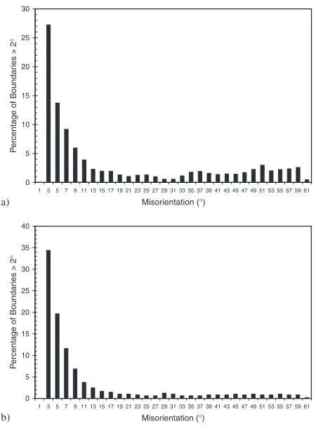
it is also evident that isolated segments of higher angle boundaries are generated during deformation. Typical exam-ples of this are given in Fig. 1 for both hot worked ferrite (commercial Ti-IF steel) and hot worked aluminium (com-mercial purity 1050 alloy). These Electron Backscattering Diffraction (EBSD) images were produced from samples subjected to elevated temperature torsion followed by quenching in water. Boundaries with a misorientation greater than 15are shown in bold and a number of segments of new high angle boundary divorced from the original boundaries can be clearly seen. The misorientations present in these structures are shown as histograms in Fig. 2. The significant presence of misorientations over the whole low angle boundary range, i.e. not just at the low end, is consistent *Corresponding author, E-mail: [email protected]
with a significant increase in certain subgrain boundary misorientations with increasing strain.
One rationale for the generation of new segments of higher angle boundary can be given as follows. During the random variations in crystallographic rotation during deformation, isolated subgrains can end up at orientations where the crystallographic rotation rate (or direction) is different from that of the rest of the grain. Subsequent deformation can then lead to systematic differences in crystallographic rotation and, under certain circumstances, to a systematic increase in misorientation. An extreme example of the latter stage of this scenario can be found in the deformation of crystals in which the crystallographic rotation induced by deformation is equally probable in two different but symmetric directions. Under these conditions one part of the grain may rotate in one direction while the other takes an opposite path. This occurs in the plane strain deformation of cube orientations in aluminium and leads to the generation of deformation bands.15) In torsion simulations of fcc deformation it has been shown that the crystallographic rotation fields are such
that the probability is high for a significant variation in rotation paths to arise for adjacent subgrains within the major texture components.12)
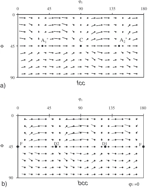
To illustrate, the crystallographic rotation field forfcc de-formation is shown in Fig. 3a. This figure was calculated us-ing a full constraint Taylor crystal plasticity model in which a shear strain of 0.15 was applied. The only operative deforma-tion mode was assumed to be the {111}h110i slip system. The lines shown are projections of the crystallographic dis-placement vectors onto the ’2¼0 section of Euler space
(Bunge convention). For calculation of the Euler angles, the torsion axial direction, z, was assigned to the Yð2Þaxis, the shear directionto theXð1Þaxis and the radial direction,
r, to theZð3Þdirection. In all of the main orientations shown, the crystallographic rotation on one ‘‘side’’ of the stable ori-entation is directed towards the stable oriori-entation while on the other the crystallographic displacement vector points away from the stable orientation. The effect of this is that a subgrain misoriented slightly from the stable orientation may rapidly rotate away from the grain orientation, thus gen-erating a significant increase in local misorientation.
Also shown in Fig. 3 is a rotation field forbccdeformation, assuming operation of the {110}h111i and {112}h111i slip systems. This plot shows the same general features as for the
fcc simulation. In what follows, subgrain boundary misor-ientations are simulated by applying full constraint Taylor simulations to tightly grouped clouds of orientations centered on the key orientation components in both fcc and bcc
systems.
100
µ
m
a)
50 µm
b)
Fig. 1 EBSD images of a) hot worked 1050 Al (450C, 0.01 s1,""¼2,
average subgrain size8mm) and b) Ti-IF steel (765C, 1 s1,""¼2,
average subgrain size2mm) showing high angle grain boundaries (in black) and Kikuchi band contrast (in grey). The samples were both deformed in torsion and quenched immediately following deformation. The shear direction is vertical and the axial direction (shear plane normal) is horizontal.
0 5 10 15 20 25 30
Misorientation (°)
P
e
rcentage of Boundar
ies > 2
°
a)
0 5 10 15 20 25 30 35 40
1 3 5 7 9 11 13 15 17 19 21 23 25 27 29 31 33 35 37 39 41 43 45 47 49 51 53 55 57 59 61 1 3 5 7 9 11 13 15 17 19 21 23 25 27 29 31 33 35 37 39 41 43 45 47 49 51 53 55 57 59 61
Misorientation (°)
P
ercentage of Boundar
ies > 2
°
b)
[image:2.595.315.540.70.375.2] [image:2.595.59.277.70.449.2]3. Simulations
The initial clouds of orientations were created, using ran-dom number generation that takes into account the non-uni-formity of orientation space, such that the average misorien-tation amongst individual components of the clouds was one degree. Clouds of 400 orientations were generated around each of the main components shown in Tables 1 and 2.13,16) The distributions of the aggregates of the misorientations be-tween individual components within the clouds are presented in Fig. 4 for both thefccandbcccases. A shear strain of 1 was applied to the initial orientation clouds using a full constraint Taylor simulation. The simulations employed the {111}
h110i slip systems for the fcccase and the {110}h111iand {112}h111i systems (with equal values of critical resolved shear stress) for thebcccase. The axes along which the
defor-mation was applied are the same as that described for the cal-culation of Fig. 3. Following the simulation, pole figures (h111ifor fccandh110i forbcc), misorientation angles and misorientation axes were calculated.
4. Simulation Results
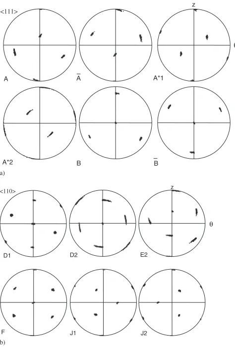
The orientation clouds following a simulated shear strain of 1 are plotted as pole figures in Fig. 5. Two interesting observations can be made:
1) The orientation spread varies significantly amongst the orientations but does not seem to be obviously different for the two crystal systems. The spread is quite large in some cases signifying that there is at least some increase in misorientation upon the application of strain. 2) The orientation spread in a number of cases is
character-ized by a rotation around the centre of the pole figure, which represents the sample radial direction. This rota-tion corresponds to the overriding ‘‘right to left’’ flow evident in the rotation field plots shown in Fig. 3.
0
1
A1* C A2*
45
Φ
Φ
90
0 45 90 135 180
ϕ1
ϕ1
A1* C A2*
D2 D1 F
F 0
45
90
0 45 90 135 180
D2 D1 F
F
bcc fcc
a)
b) ϕ2=0
[image:3.595.49.289.76.381.2]Fig. 3 Crystallographic rotation fields predicted for fixed end torsion using a full constraint Taylor crystal plasticity model for a)fccsystems (slip on {111}h110i) and b)bccsystems (slip on {110}h111iand {112}h111i). Orientations predicted to be stable are shown — see Tables 1 and 2 for definitions.
Table 1 Main torsion texture components forfccmetals (after13Þ).
Orientation Miller indices ’1 ’2
A ð1111Þb1110c 0.0 35.3 45.0
A
A ð11111Þb1110c 180.0 35.3 45.0
A
1 ð1111Þb2111c 35.3 45.0 0.0
A
2 ð1111Þb22111c 144.7 45.0 0.0
B ð1122Þb1110c 0.0 54.7 45.0
B
B ð11112Þb1110c 180.0 54.7 45.0
C ð100Þb0111c 90.0 45.0 0.0
Table 2 Main torsion texture components forbccmetals (after16Þwith a
correction for J2).
Orientation Miller indices ’1 ’2
F (110)[001] 180.0 45.0 0.0
D1 ð1122Þ½111 125.3 45.0 0.0
D2 ð11112Þ½111 54.7 45.0 0.0
E2 ð0111Þ½111 90.0 35.3 45.0
J1 ð0111Þb2211c 30.0 54.7 45.0
J2 ð1110Þb11112c 90 54.7 45.0
0 2 4 6 8 10 12 14 16 18 20
0.1 0.3 0.5 0.7 0.9 1.1 1.3 1.5 1.7 1.9 2.1 2.3 2.5 2.7 Misorientation (°)
P
ercentage of Boundar
ies
a)
0 2 4 6 8 10 12 14 16 18 20
0.1 0.3 0.5 0.7 0.9 1.1 1.3 1.5 1.7 1.9 2.1 2.3 2.5 2.7 Misorientation (°)
P
ercentage of Boundar
ies
b)
Fig. 4 Distribution of misorientations for the initial orientation ‘‘clouds’’ employed in the simulation of boundary generation for a)fccand b)bcc
[image:3.595.311.539.88.482.2] [image:3.595.46.291.685.786.2]To examine the first of these, the aggregates of the misorientations produced in the simulations are plotted in Fig. 6. For each orientation cloud, 400 orientation pairs were randomly selected for inclusion in the aggregate misorienta-tion distribumisorienta-tion. These plots should be contrasted with the initial misorientation distributions shown in Fig. 4. It is evident that the misorientations have increased markedly with the application of a simulated strain. The maximum misorientation within the initial clouds is of the order of 2 whereas following deformation the maximum simulated misorientation is in the order of 16-20. Overall, thebccand
fcc simulations gave rise to very similar distributions of misorientations.
Further insight into the nature of the rotations that generate these higher misorientations can be gained by plotting the axes that correspond to each misorientation angle employed in the generation of Fig. 6. These axes are plotted in the sample reference system (i.e.on pole figures) in Fig. 7. What is interesting to note in these plots is that the dominant orientation of the misorientation axis is in the radial direction. As mentioned above, this reflects the predominance of the ‘‘left to right’’ rotation evident in the rotation fields shown in Fig. 3. That is, misorientations generated by this mechanism
can be expected to have a misorientation axis close to the sample radial direction. It is also evident in Fig. 7 that the higher misorientations show a closer alignment of the misorientation axes with the radial direction.
5. Discussion
The simulations carried out here are highly idealized. However, the initial spread of orientations can be thought of as representing an array of subgrains delineated by Incidental Dislocation Boundaries. The simulations in one sense, therefore, show the evolution of IDBs into Geometrically Necessary Boundaries (The higher misorientations can be thought of as GNBs because they form due to systematic differences in deformation either side of the boundary.). In reality the situation is more complex. For one, the random variation of dislocation fluxes will continue during straining. This would seem to suggest that the simulations under-estimate the rate of misorientation generation. However, this phenomenon can actually decrease the misorientation by allowing all of the orientations around the stable texture components to ‘‘tunnel’’ through and catch up to other subgrains that may have previously done the same, thus reducing the misorientation between them.
It is of interest that there appears to be only minor differences between thefccandbccsimulations. This is to be
<111>
A A A*1
A*2 B B
z
a)
<110>
D1 D2 E2
F J1 J2
z
b)
θ
θ
Fig. 5 Pole figures showing the orientation produced following a simulated shear strain of 1 imposed on orientation clouds centred on some (due to space limitations) of the main torsion texture components. In a)h111ipole figures are shown for thefccresults. In b)h110ipole figures are employed for thebccdata.
0 5 10 15 20 25 30 35
0.5 1.5 2.5 3.5 4.5 5.5 6.5 7.5 8.5 9.5 10.5 11.5 12.5 13.5 14.5 15.5 16.5 17.5 18.5 19.5 20.5
0.5 1.5 2.5 3.5 4.5 5.5 6.5 7.5 8.5 9.5 10.5 11.5 12.5 13.5 14.5 15.5 16.5 17.5 18.5 19.5 20.5
Misorientation (°)
P
e
rcentage of Boundar
ies
a)
0 5 10 15 20 25 30 35
Misorientation (°)
P
e
rcentage of Boundar
ies
b)
Fig. 6 Misorientations produced by the simulation of a shear strain of 1 imposed on the original orientation clouds, the misorientations within which are shown above in Fig. 4. Thefccresults are shown in a) and the
[image:4.595.49.286.73.423.2] [image:4.595.310.546.77.390.2]expected due to the inverse relationship of the {111}h110i
and {110}h111i slip systems in the fcc and bcc systems respectively. However, what the results show is that the addition of {112}h111islip in thebcccase has little effect.
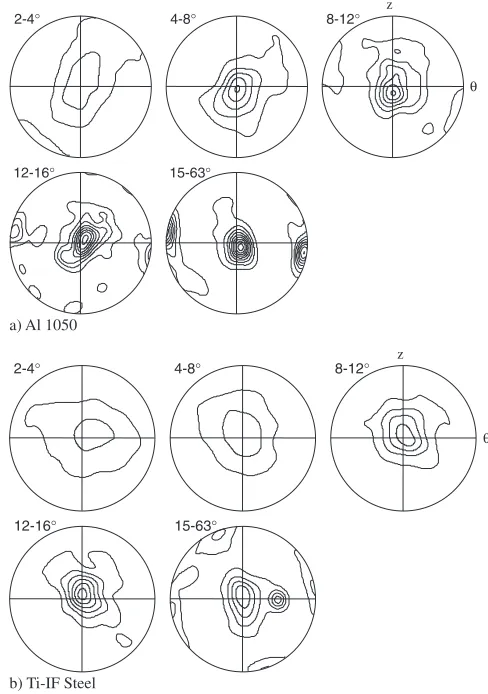
To verify if these findings have any experimental support the misorientation axes calculated for all the misorientations greater than 2present in the two hot worked samples shown in Fig. 1 are presented in Fig. 8. The misorientations less than 15can be considered to be due largely to the action of defor-mation while those greater than this value are influenced by the nature of the texture in addition to the generation of
new boundaries. It is clear that the misorientation axes are clustered around the radial direction for both the Al 1050 al-loy and the Ti-IF steel for the low angle boundaries. This is consistent with the simulations carried out here and lends sup-port for the role of the crystallographic rotation field in shear in generating misorientations in bothfccandbccmetals.
For the sake of contrast, it is interesting to briefly consider if a similar phenomenon occurs in rolling. In this case the situation is somewhat more complicated because, unlike torsion, the main rolling texture components do not com-pletely coincide with the stable orientations predicted by full constraint Taylor simulation.17)For the case of rolling ofbcc
systems, the full constraint model predicts that near {112}h110i and near {443}h338i orientations should be stable. Clouds of 400 orientations were therefore generated about these orientations in a similar manner to that employed above for the torsion simulations. The average misorientation within the initial cloud of orientations was 1and a von Mises strain of 0.58 was applied in the model (for equivalence to the shear strain of 1 used in the torsion simulations). The misorientations before and after the simulated deformation are shown in Fig. 9. In contrast with torsion (Fig. 6), the orientation clouds subjected to rolling deformation aremore
tightly grouped after deformation than before. For the stable orientations examined the crystallographic rotation field does
2-4° 4-8°
8-12° 12-16°
θ
θ
z
a)
fcc
2-4° 2-8° z
8-12° 12-16°
b)
bcc
Fig. 7 Pole figures showing the orientation of the misorientation axes corresponding to the misorientations generated in the simulations for different misorientation classes. The plots in a) refer to thefccsimulations while those in b) are for thebccresults. Intensity levels: 1, 2, 4, 8,. . ..
2-4° 4-8° 8-12°
θ
θ
12-16° 15-63°
z
a) Al 1050
2-4° 4-8° 8-12°
12-16° 15-63°
z
b) Ti-IF Steel
[image:5.595.302.546.75.422.2] [image:5.595.48.289.81.581.2]not give rise to increasing misorientations. Further work is required to ascertain if this difference is maintained for orientations chosen at random.
The difference observed between the rolling and torsion simulations suggests that the present phenomenon is re-stricted to shear deformation. However, it may manifest itself during rolling if the deformation becomes localized in shear bands. In these situations the mechanism discussed here is likely to operate within the sheared regions. Of course, additional generation of GNBs is also expected at the boundaries between the sheared and non-sheared regions. In general, the present mechanism can be considered to aug-ment the better known processes by which GNBs and higher angle subgrain boundaries are generated during shear deformation. Its role can be expected to diminish if the shear component of the deformation drops or if the contribution of grain boundary sliding to the overall deformation increases.
6. Conclusion
Simulations have shown that clouds of orientations centred on the main torsion texture components increase in spread with the application of ideal Taylor shear. This occurs both in
fccandbcc simulations and the main characteristics of the boundaries thus generated (i.e. a rotation axis close in alignment to the torsion radial direction) appear in exper-imental results for Al 1050 and Ti-IF steel. The same effect does not appear in simulations ofbccstructures subjected to rolling. Shear deformation, by its nature, facilitates the generation of higher misorientations.
Acknowledgements
Thanks to C. Tome and J-C. Glez for permission to use their texture simulation software and to the French Govern-ment Scientific Fellowship Scheme and the Australian Research Council’s Large grant scheme for financial support.
REFERENCES
1) D. A. Hughes and N. Hansen: Acta. Meter.48(2000) 2985–3004. 2) N. Hansen: Metall. Meter. Trans. A32A(2001) 2917–2935. 3) F. J. Humphreys and M. Hatherly: Recrystallization and Related
Annealing Phenomena, (Elsevier, Oxford, 1996), 242.
4) Q. Liu, D. J. Jensen and N. Hansen: Acta Mater.46(1998) 5819–5838. 5) D. Raabe, Z. Zhao, S. J. Park and F. Roters: Acta Mater.50(2002) 421–
440.
6) D. A. Hughes and N. Hansen: Acta Mater.45(1997) 3871–3886. 7) M. R. Barnett: ISIJ Int.38(1998) 78–85.
8) M. R. Drury and F. J. Humphreys: Acta Metall.34(1986) 2259–2271. 9) R. Kaibyshev, A. Goloborodko, F. Musin, I. Nikulin and T. Sakai:
Mater. Trans.43(2002) 2408–2414.
10) S. Gourdet and F. Montheillet: Mater. Sci. Eng. A283A(2002) 274– 288.
11) T. Sakai and J. J. Jonas: Acta Metall.32(1984) 189–209.
12) M. R. Barnett and F. Montheillet: Acta Mater.50(2002) 2285–2296. 13) J. Baczynski and J. J. Jonas: Metall. Mater. Trans.29A(1998) 447–
462.
14) J. K. Solberg, H. J. McQueen, N. Ryun and E. Nes: Philos. Mag. A60 (1989) 447–471.
15) J. H. Driver, M. C. Theyssier and C. Maurice: Mater. Sci. Technol.12 (1996) 851–858.
16) L. S. Toth, P. Gilormini and J. J. Jonas: Acta Metall.36(1988) 3077– 3091.
17) L. S. Toth, J. J. Jonas, D. Daniel and R. K. Ray: Metall. Trans.21A (1990) 2985–3000.
0 2 4 6 8 10 12 14 16 18
0.1 0.3 0.5 0.7 0.9 1.1 1.3 1.5 1.7 1.9 2.1 2.3 2.5 2.7 Misorientation (°)
P
ercentage of Boundar
ies
0 5 10 15 20 25
P
ercentage of Boundar
ies
0 5 10 15 20 25 30
P
e
rcentage of Boundar
ies
0 5 10 15 20 25
P
ercentage of Boundar
ies
a)
b)
c)
d)
{112}<110> Initial {112}<110> ε=0.58
{443}<338> Initialial {443}<338> ε=0.58
0.1 0.3 0.5 0.7 0.9 1.1 1.3 1.5 1.7 1.9 2.1 2.3 2.5 2.7 0.1 0.3 0.5 0.7 0.9 1.1 1.3 1.5 1.7 1.9 2.1 2.3 2.5 2.7 0.1 0.3 0.5 0.7 0.9 1.1 1.3 1.5 1.7 1.9 2.1 2.3 2.5 2.7
Misorientation (°) Misorientation (°)
Misorientation (°)
[image:6.595.101.498.72.331.2]