Dense P/M Component Produced by Solid Freeform Fabrication (SFF)
Hideki Kakisawa
1;*, Kazumi Minagawa
1, Keisuke Ida
2, Katsuhiro Maekawa
3and Kohmei Halada
11Ecomaterials Research Center, National Institute for Materials Science, Tsukuba 305-0047, Japan 2Graduate School of Science and Engineering, Ibaraki University, Hitachi 316-8511, Japan 3
Research Center for Superplasticity, Faculty of Engineering, Ibaraki University, Hitachi 316-8511, Japan
Using fine metal powders, we were able to fabricate dense P/M (powder metallurgy) products by a three-dimensional inkjet printing system. We used carbonyl nickel powder with a mean particle size of 5mmas a raw material and examined two binder supply methods: (i) supplying a binder directly from the inkjet head (DB method), and (ii) coating the powder with a water-soluble polymer and then supplying thin polymer-dissolved water from the inkjet head (CB method). The layered green product was sintered in a hydrogen atmosphere at a temperature in the range of 1073–1623 K. Sintered samples fabricated by the CB method had non-uniform microstructure due to agglomeration of the coated powder. In samples made by the DB method, the macroscopic shape was retained after high-temperature sintering at 1623 K, and a high density of over 90% was achieved, which was attributed to uniform powder cohesion in the laminating process.
(Received June 28, 2005; Accepted August 22, 2005; Published December 15, 2005)
Keywords: solid freeform fabrication, Rapid prototyping, three-dimensional printing, metal powder
1. Introduction
Solid freeform fabrication (SFF) techniques, designated as rapid prototyping or die-free fabrication, have been of considerable interest as a flexible manufacturing method. It can fabricate complex product components in net shape or near-net shape directly from three-dimensional (3D) com-puter-aided design (CAD) data. With the sliced cross-sectional data converted from the 3D CAD data, structural and functional components of products are built up layer by layer from bottom to top. Neither complex die nor complex machining is needed to form the components, saving significant time and cost. Also, we can easily change the size and design of the parts using just a desktop computer. Because of its efficiency and flexibility, this technique is attracting attention as an environmentally benign type of manufacturing.
Among SFF techniques, the most promising methods for the production of metal components are the ones that make components by bonding metal powders: laser sintering and 3D printing are the candidates in this category. Selective laser sintering (SLS)1–5)has been widely studied in the application to metal and alloy powders. In this process, a CO2 or Nd:YAG laser is usually used as a heat source and selectively scans a powder bed of the powder spread on a flat stage, to join the powder in the designed shape of the cross section. After the first cross section is scanned, the powder for the second layer is spread on it, and the scanning and joining process are repeated until the component is completed. Direct metal laser sintering (DMLS), which is an SLS variant, provides the powder high energy to heat over the melting temperature, and directly sinters the component. DMLS has an advantage of shaping relatively dense parts (full density of 80%) and requiring no post-sintering process (e.g., infiltra-tion, heat treatment, etc.). However, the high-energy laser beam in DMLS causes the microstructure of the component to be significantly coarse, or ruins the unique microstructure of powder because of liquid sintering. It is therefore difficult
to fully utilize the intrinsic strength and other properties of the powder. Porosities left between melt tracks and gaps remaining at layer boundaries are also problems with this method, as they result in a non-uniform, laminated structure of the final product. In addition, thermal stress induced during local sintering sometimes causes the component to be distorted.
In the 3D printing technique,6–14)which was invented at Massachusetts Institute of Technology, there is an inkjet printer head instead of a laser source, and it prints a cross-sectional picture on the powder bed with a binder from the head, The powder at the scanned area is joined by the supplied binder. Then the new powder for the next layer is spread just like in SLS, and the printing process is repeated until all of the needed layers are stacked. This type of 3D printing is mainly used for polymers and ceramics, especially in the field of medical materials, because green ceramics components can be made with high accuracy. There are excellent advantages in the application of 3D printing to metal powders, too; for instance, fabrication of green components can be done at room temperature in an oxidation-free condition. To produce P/M components utilizing a particular powder microstructure such as nano-crystallized and amorphous microstructures, a low-temper-ature hysteresis during formation of the green part followed by solid sintering is a good solution.
A 3D printing machine for metal powder has been commercialized; however, it has weak points, such as the low density of the final components caused by the loose green components. Usually the components need a post-sintering process, e.g., infiltration of metals with a low melting temperature such as brass after sintering. In this study, to obtain a dense P/M component with a uniform micro-structure, we used an extremely fine powder of 5mm(in usual SFFs, powders are several tens ofmm) in 3D printing. We investigated two types of binder-supplying methods: (i) supplying a binder directly from the inkjet head (DB method), and (ii) coating the powder with a water-soluble polymer in advance, and supplying water (or thin polymer-dissolved water) from the inkjet head (CB method). We *Corresponding author, E-mail: [email protected]
Special Issue on Growth of Ecomaterials as a Key to Eco-Society II
discuss here the optimum conditions we found, based on the density and microstructure of the samples sintered at various temperatures.
2. Experimental Procedure
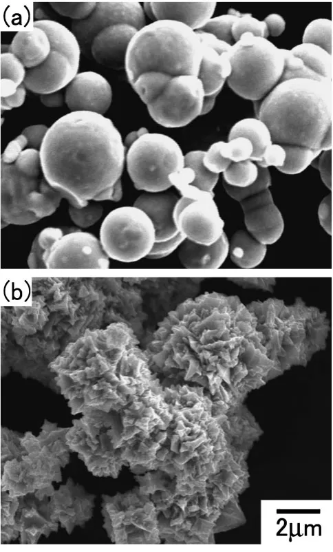
[image:2.595.48.290.361.762.2]The powder used in this study was spherical carbonyl nickel powder with a relatively uniform particle size (mean diameter: 5mm). Two powders with a smooth surface and roughened spiky surface were prepared for CB and DB, respectively. Appearances of the powders are shown in Fig. 1.
For CB, 99 g nickel powder was mixed with 1 g water-soluble starch (mean diameter: approximately 70mm) and ball-milled in a horizontal cylinder with a diameter of 100 mm and a length of 200 mm. The powder was coated with starch during the milling. A mixture of 200 g glass balls with three sizes (diameter: 2, 6, 10 mm) was used to prevent agglomeration of the powders during the coating treatment. The coating time was varied from 3.6 to 36 ks. After the coating some of the powder was screened to sizes of 42, 125, and 300mm, because the starch causes strong
bonding between powders during the coating. As a prelimi-nary study to determine the optimum coating time, we spread the coated powder on a powder bed of 1010mm at a thickness of 100mmby hand using a spatula. Then polymer-dissolved water of about 1–2mL (ZB4: Z Corporation, USA), which was specially developed to bond starch in a 3D printing system, was sprayed on it. Repeating the procedure, a green part of a thickness of about 8 mm was fabricated and sintered at 873 K in a hydrogen atmosphere for 3.6 ks. We observed the microstructure of the sintered sample by optical microscopy.
For DB, polyvinyl alcohol (PVA) solution was prepared as a binder to be supplied via the inkjet head. The concentration of the binder was 3.8%, and the polymerization was approximately 200.
A 3D printing machine (Z402: Z Corporation, USA) was used to fabricate metal samples. Figure 2 shows the schematic illustration of the 3D printing process. A 3D CAD model of a given specimen was converted to STL format and then sliced into a stack of thin layers. The data of each layer was sent to the 3D printing machine. Loose powder for a layer was carried from the powder-supplying stage and spread over the building stage by a spinning roller. A cross section of a single layer was printed on the powder bed of the building stage according to the data sent (see (1) in Fig. 2). Then the building stage was lowered by the layer thickness and new powder for the next layer was spread over the previous layer [(2) and (3) in Fig. 2]. This series of steps was repeated until the part was completely built.
In the CB method, we used starch-coated nickel powder and ZB4 was supplied from the head at a ZB4 to powder ratio of 0.175. In the DB method, PVA binder was supplied from the head on raw nickel powder. The ratio of binder to powder was varied from 0.1 to 0.4. The laminating pitch, i.e., the layer thickness, was basically set at 90–100mm, but a thickness of 200mm was also used in some of the tests. Rectangular prisms of several sizes, typically5513mm in designed size, were fabricated.
After the printing, the sample was dried in the powder bed for 1.8 ks and then was dug from the bed. The sample was pre-sintered in hydrogen atmosphere at 873 K for 7.2 ks to remove PVA and then sintered in hydrogen atmosphere at a
Fig. 1 Appearances of carbonyl nickel powder used in: (a) the CB method, and (b) the DB method.
(spinning)
[image:2.595.307.549.606.767.2]temperature of 1073–1473 K for a given sintering time of 3.6–36 ks. Because of the limitation of the furnace, sintering at 1623 K was done not in hydrogen but in a vacuum. The heating rate was constant at 10 K/min through the sintering. The density of the sintered samples was measured by an Archimedes method. The sintered samples were cut perpen-dicular and parallel to the layer and polished. The polished cross sections were observed by optical and scanning electron microscopy (SEM).
3. Results
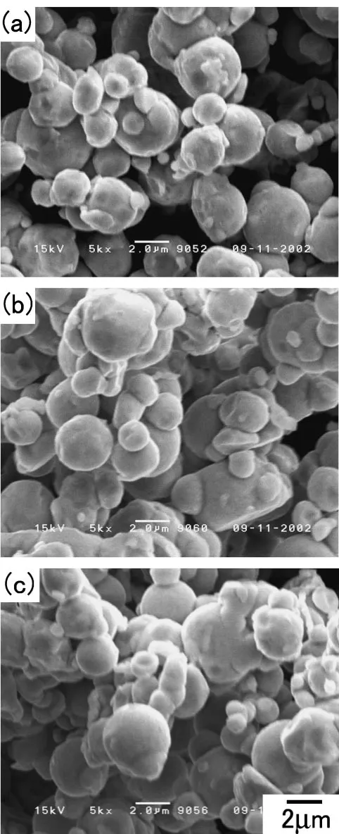
Figure 3 shows the surface appearances of the coated powder. Starch was spread on the powder surface while the powder remained spherical. At a short coating time of 3.6 ks, starch was patchily adhered on the powder, and as the coating time increased, the coated area increased. Complete coating covering the entire surface was done at 10.8 ks. The coated powder was agglomerated by the starch because of its high adhesive strength. The agglomerated particles grew as the coating time increased: they were about 10mmat 3.6 ks but over 20mmat 10.8 ks. At the longer coating times of 18 and 36 ks, some of the powder was buried in the starch coating and the powder particles were strongly stuck to each other. Agglomerated particles were over 100mm in diameter in these time ranges.
Figure 4 shows the cross section of the samples laminated by manual powder deposition (sintered at 873 K). The powders coated for 18 and 36 ks were too much agglomerated (over 100mmdiameter) to be used in laminating by 100mm. The sample from the powder coated for 3.6 ks had large pores of several hundred mm. The powder packing was loose and irregular, with a small amount of patchily distributed binder, so some areas were isolated during sintering and fell away in polishing. The sample from the powder coated for 10.8 ks showed a relatively uniform microstructure without signifi-cantly large pores. The entire starch coating contributed to strong cohesion and bonding between the powders, which resulted in good sinterability. We found that a sufficient amount of binder coating was needed to obtain solid and uniform sintered samples. Therefore, the powders coated for 10.8 ks and longer than 10.8 ks were used for the following experiment.
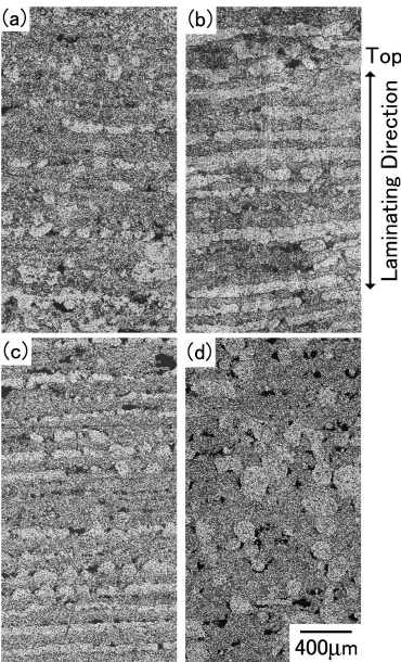
Figure 5 shows cross sections of the samples fabricated by the CB method using the 3D printing machine (after sintering at 873 K). In the sample from the powder coated at 10.8 ks with a laminating pitch of 100mm, partially dense parts (bright areas in the photograph) were aligned in the layers. The dense areas were thought to originate from agglomerated particles; agglomerated particles seemed to snowball as they were fed by the roller. Pores approximately 10mm in size existed in the vicinity of the dense areas, indicating that powder feeding near the agglomerated particles was ob-structed by them. In the porous areas, the microstructure was relatively uniform and boundaries between layers were not clear.
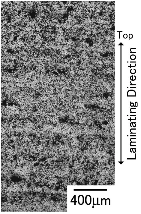
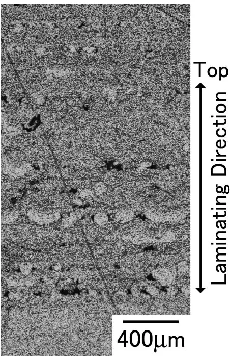
In the samples from the powder coated for 10.8 and 18 ks with a laminating pitch of 200mm [Figs. 5(b) and (c)], a dense part approximately 100mmin thickness formed on the upper side within a single laminating layer, while a coarse
porous part formed on the lower side. During powder feeding, the large agglomerated particles and fine primary powder were separated and ended up on the upper and lower sides as they were beaten by the spinning roller. The area fraction of the dense parts was larger than that in the samples
[image:3.595.306.547.69.661.2]with 100mmlaminating pitch, which suggested that there was a greater snowball effect at a laminating pitch of 200mm, with a larger amount of powder carried.
With the coating time of 36 ks, boundaries between the laminating layers were not observed. The dense areas were about 200mm in diameter, reflecting the large bonded particles formed during the coating and the powder feeding. The location of the dense areas was relatively random, probably because the particles made with 36 ks coating were so large that they were pushed into the previous layer by the roller.
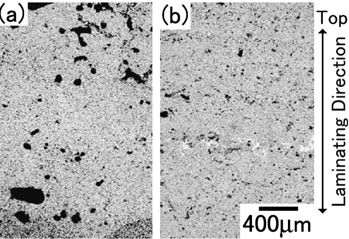
Figure 6 shows the cross section of the samples fabricated by the DB method (after sintering at 873 K). The micro-structure was very homogeneous. The distribution of pores was uniform, with no locally dense areas or large pores. We observed no boundaries between the layers and no density difference within the layers. There were no significant differences in microstructure with the different amounts of binder. Figure 7 shows the detailed microstructure of the sintered samples. Networks of the powders were formed, and the small pores were found to be the spaces between powders at 873 K. The binder was removed after pre-sintering at 873 K for 7.2 ks. Both pyrolysis of PVA and the beginning of neck growth between powders occurred below 873 K, which was important to keep the shape of the green samples during pyrolysis; this made it possible for the following densifica-tion procedure to occur at higher temperatures.
The relation between the density of the sintered DB samples and sintering temperature is plotted in Fig. 8. As the sintering temperature increased, the density of the sample increased. At 873 K the density was 34% as measured by an Archimedes method, which was comparable to that fabri-cated by the CB method at the same temperature. At the highest sintering temperature tested, 1623 K, the density reached 82%. The density of the samples joined by the binder
at an amount of 10 vol% of the powder was slightly smaller than that of samples with 40 vol% binder at low temperatures, but it caught up at 1273 K and became the same at the higher temperatures. The density increased also by increasing sintering time, as shown in Fig. 9. The increase of the density saturated with time; 91% of the full density was obtained at 1623 K for 36 ks.
Figure 10 shows the appearance of the sintered sample (3:3103:5mm) fabricated by the DB method. The rectangular prism shape was tolerably retained even after sintering at 1623 K without bending or distortion. The samples were gray colored at low sintering temperatures and gained a metallic gloss with the increase of sintering temperature. Shape accuracy was good at the top surface of the sample, with sharp edges and a flat surface. At the bottom, the surface was swelled and the edges became round, because the binder soaked into the neighboring powder around the sample over the designed area.
4. Discussion
In the CB method, we assumed that the agglomeration of the powder during both coating and feeding caused the non-uniform microstructure, and the inhomogeneous density distribution caused irregular sintering in the sample. Figure 11 shows the cross section of the sample from the 10.8 ks coated powder screened by a 42mmsieve (sintered at 873 K). Both the total area and the number of dense parts decreased significantly, confirming that the bonded particles were the origin of the dense area. The uniform microstructure of the porous area suggests that uniform densification would occur if the agglomeration could be inhibited. However, complete elimination of the particles was difficult. It was inevitable that a new agglomeration occurred during the powder feeding by the roller, partially because the
[image:4.595.129.469.72.305.2]soluble starch was very susceptible to moisture and the particles easily cohered with each other. The results suggested that we should severely control the humidity in utilizing a starch binder. The powder feeding method could be modified as well; the preliminary experiment, in which the
powder was carried with not a roller but a spatula, might be a good hint.
The successful results in the DB method were attributed to the homogeneous microstructure with a uniform distribution of small pores. That allowed regular sintering at any place
[image:5.595.112.482.67.677.2]and resulted in good shape retention of the samples after sintering. It has been reported that the amount of the binder supplied has a strong influence on microstructure.13) The
proportion of binder supply was changed within a wide range of 10–40 vol% of the powder volume; it had little influence on the microstructure in this study. Viscosity of the binder was very low, 2.7–2.8 MPas, so the binder could impregnate into every space between the powders with a relatively small amount of binder supply. The slight difference in density with changing the binder amount was probably because a larger capillary force to cohere was in effect with the larger amounts of binder, but the effect was small and was canceled at high temperatures.
The amount of binder affected the macroscopic properties as well as the microstructure. Handling of the green samples was easier with a high volume of binder supply, though the green samples fabricated in this study were all very break-able. However, supplying the binder to excess caused exudation of the binder to the sides and bottom of the laminated green sample in the powder bed, and it resulted in the expansion of the sample. This expansion was the most significant at the bottom, and it caused the swelling of the final sintered sample at the bottom face. The swelling at the bottom occurred regardless of the amount of binder tested. High infiltration ability with low viscosity did it harm in this
phase. With a binder having a higher strength and appropriate viscosity, the accuracy of the sintered sample would be improved further.
5. Conclusion
To obtain a dense P/M component with a uniform microstructure, we used a fine carbonyl nickel powder of
Fig. 6 Microstructures of the sample from raw nickel powder bonded by PVA (pre-sintered at 873 K).
[image:6.595.308.548.68.616.2] [image:6.595.53.288.72.427.2]5mm in 3D printing. Two binder supply methods, the DB method and CB method, were examined and the following conclusions were obtained:
(1) Water-soluble starch coating on the powder was successfully done by a ball-milling technique. Agglom-eration of the coated powder occurred during both coating and feeding to the powder bed. It caused a non-uniform microstructure of dense and porous parts. Density variation in the samples was improved by screening agglomerated particles after the coating. However, it was difficult to eliminate agglomeration completely because of the nature of starch to cohere easily. The uniformity at the porous parts without layer boundaries showed the possibilities for obtaining a uniform microstructure; some room for improvement remains.
(2) In the DB method, using a PVA binder, a very homogeneous microstructure that was free from any layer boundary or density variation was obtained. It led to good sintered samples with good shape retention and
no distortion. A high density of over 90% was achieved after sintering at 1623 K for 36 ks. It was clearly shown that the combination of fine metal powder and appro-priate direct binder supply from an inkjet head had a high potential for obtaining uniform, dense P/M parts with good shape accuracy.
30 40 50 60 70 80 90
800 1000 1200 1400 1600 1800 40%
10%
(Supplied binder ratio to powder volume)
Sintering Temperature, T/K
Relative Density (%)
(Sintered for 3.6ks)
Fig. 8 Relation between relative density and sintering temperature.
Sintering Time, t/ks (Sintered at 1623K)
80 82 84 86 88 90 92
0 5 10 15 20 25 30 35 40
Relative Density (%)
(Binder amount: 40% of powder)
[image:7.595.313.542.74.240.2]Fig. 9 Relation between relative density and sintering time.
[image:7.595.57.283.74.262.2]Fig. 10 Appearance of a laminated and sintered sample (sintered at 1623 K for 3.6 ks). The dimension of the sample is3:3103:5mm.
[image:7.595.313.539.297.646.2] [image:7.595.57.283.315.502.2]REFERENCES
1) D. L. Bourell, H. L. Marcus, J. W. Barlow and J. J. Beaman: Int. J. Powder Metall.28(1992) 369–381.
2) S. Das, M. Wohlert, J. J. Beaman and D. L. Bourell: JOM50(1998) 17– 20.
3) R. Irving: Int. J. Powder Metall.36(2000) 69–74.
4) P. Fischer, A. Blatter, V. Romano and H. P. Weber: Appl. Phys. A80
(2005) 489–492.
5) R. Morgan, C. J. Sutcliffe and W. O’neill: J. Mater. Sci.39(2004) 1195–1205.
6) K. Matsuura, T. Koyanagi, M. Kudoh, J. H. Oh, S. Kirihara and Y. Miyamoto: Mater. Trans.43(2002) 1146–1152.
7) E. Sachs, M. Cima, P. Williams, D. Brancazio and J. Cornie: J. Eng. Industry-Trans. ASME114(1992) 481–488.
8) J. Yoo, K. M. Cho, W. S. Bae, M. Cima and S. Suresh: J. Am. Ceram. Soc.81(1998) 21–32.
9) A. Lorenz, E. Sachs, S. Allen, L. Rafflenbeul and B. Kernan: Metall. Mater. Trans. A35A(2004) 631–640.
10) W. Sun, D. J. Dcosta, F. Lin and T. El-Raghy: J. Mater. Process. Tech.
127(2002) 343–351.
11) S. B. Hong, N. Eliaz, G. G. Leisk and E. M. Sachs: J. Dental Res.80
(2001) 860–863.
12) M. C. Melican, M. C. Zimmerman, M. S. Dhillon, A. R. Ponnambalam, A. Curodeau and J. R. Parsons: J. Biomedical Mater. Res.55(2001) 194–202.
13) J. Moon, A. C. Caballero, L. Hozer, Y. M. Chiang and M. J. Cima: Mater. Sci. Eng. A298(2001) 110–119.
14) C. R. Rambo, N. Travitzky, K. Zimmermann and P. Greil: Mater. Lett.