University of Wollongong University of Wollongong
Research Online
Research Online
University of Wollongong Thesis Collection
2017+ University of Wollongong Thesis Collections
2018
Active suspension control of electric vehicle with in-wheel motors
Active suspension control of electric vehicle with in-wheel motors
Xinxin ShaoUniversity of Wollongong
Follow this and additional works at: https://ro.uow.edu.au/theses1
University of Wollongong University of Wollongong
Copyright Warning Copyright Warning
You may print or download ONE copy of this document for the purpose of your own research or study. The University does not authorise you to copy, communicate or otherwise make available electronically to any other person any
copyright material contained on this site.
You are reminded of the following: This work is copyright. Apart from any use permitted under the Copyright Act 1968, no part of this work may be reproduced by any process, nor may any other exclusive right be exercised, without the permission of the author. Copyright owners are entitled to take legal action against persons who infringe
their copyright. A reproduction of material that is protected by copyright may be a copyright infringement. A court may impose penalties and award damages in relation to offences and infringements relating to copyright material.
Higher penalties may apply, and higher damages may be awarded, for offences and infringements involving the conversion of material into digital or electronic form.
Unless otherwise indicated, the views expressed in this thesis are those of the author and do not necessarily Unless otherwise indicated, the views expressed in this thesis are those of the author and do not necessarily represent the views of the University of Wollongong.
represent the views of the University of Wollongong.
Recommended Citation Recommended Citation
Shao, Xinxin, Active suspension control of electric vehicle with in-wheel motors, Doctor of Philosophy thesis, School of Electrical, Computer and Telecommunications Engineering, University of Wollongong, 2018. https://ro.uow.edu.au/theses1/377
Research Online is the open access institutional repository for the University of Wollongong. For further information contact the UOW Library: research-pubs@uow.edu.au
School of Electrical, Computer and Telecommunications Engineering Faculty of Engineering and Information Sciences
Active suspension control of electric vehicle with in-wheel motors
Xinxin Shao
"This thesis is presented as part of the requirements for the Award of the Degree of
Doctor of Philosophy From
University of Wollongong"
I
Abstract
In-wheel motor (IWM) technology has attracted increasing research interests in recent years due to the numerous advantages it offers. However, the direct attachment of IWMs to the wheels can result in an increase in the vehicle unsprung mass and a significant drop in the suspension ride comfort performance and road holding stability. Other issues such as motor bearing wear motor vibration, air-gap eccentricity and residual unbalanced radial force can adversely influence the motor vibration, passenger comfort and vehicle rollover stability. Active suspension and optimized passive suspension are possible methods deployed to improve the ride comfort and safety of electric vehicles equipped with in-wheel motor. The trade-off between ride comfort and handling stability is a major challenge in active suspension design.
This thesis investigates the development of novel active suspension systems for successful implementation of IWM technology in electric cars. Towards such aim,
several active suspension methods based on robust H∞ control methods are developed to
achieve enhanced suspension performance by overcoming the conflicting requirement
between ride comfort, suspension deflection and road holding. A novel fault-tolerant H∞
controller based on friction compensation is in the presence of system parameter uncertainties, actuator faults, as well as actuator time delay and system friction is
proposed. A friction observer-based Takagi-Sugeno (T-S) fuzzy H∞ controller is
developed for active suspension with sprung mass variation and system friction. This method is validated experimentally on a quarter car test rig. The experimental results demonstrate the effectiveness of proposed control methods in improving vehicle ride performance and road holding capability under different road profiles.
Quarter car suspension model with suspended shaft-less direct-drive motors has the potential to improve the road holding capability and ride performance. Based on the quarter car suspension with dynamic vibration absorber (DVA) model, a multi-objective parameter optimization for active suspension of IWM mounted electric vehicle based on genetic algorithm (GA) is proposed to suppress the sprung mass vibration, motor vibration, motor bearing wear as well as improving ride comfort, suspension deflection
and road holding stability. Then a fault-tolerant fuzzy H∞ control design approach for
active suspension of IWM driven electric vehicles in the presence of sprung mass variation, actuator faults and control input constraints is proposed. The T-S fuzzy suspension model is used to cope with the possible sprung mass variation. The output
II
feedback control problem for active suspension system of IWM driven electric vehicles with actuator faults and time delay is further investigated. The suspended motor parameters and vehicle suspension parameters are optimized based on the particle swarm
optimization. A robust output feedback H∞ controller is designed to guarantee the
system’s asymptotic stability and simultaneously satisfying the performance constraints. The proposed output feedback controller reveals much better performance than previous work when different actuator thrust losses and time delay occurs.
The road surface roughness is coupled with in-wheel switched reluctance motor air-gap eccentricity and the unbalanced residual vertical force. Coupling effects between road excitation and in wheel switched reluctance motor (SRM) on electric vehicle ride comfort are also analysed in this thesis. A hybrid control method including output feedback controller and SRM controller are designed to suppress SRM vibration and to prolong the SRM lifespan, while at the same time improving vehicle ride comfort. Then a state
feedback H∞ controller combined with SRM controller is designed for in-wheel SRM
driven electric vehicle with DVA structure to enhance vehicle and SRM performance. Simulation results demonstrate the effectiveness of DVA structure based active suspension system with proposed control method its ability to significantly improve the road holding capability and ride performance, as well as motor performance.
III
Acknowledgments
First and foremost, I would like to express my sincere thanks to my supervisors, Professor Fazel Naghdy, Professor Haiping Du and Professor Weihua Li for their guidance, motivation and continual support throughout my research. The achievement of this work will not be possible without their valuable expertise and helpful suggestions.
I would also like to express my deepest gratitude to Professor Nong Zhang for his guidance and support on hydraulically interconnected suspension system. I would like to particularly thank Professor Hongyi Li for his help regarding the robust control methods. I would like to express my sincere thanks to my colleagues Donghong Ning and Xin Tang for their help regarding the quarter car suspension test rig and experiment validation. Special thanks to Dr. Yechen Qin and Dr. Wei Sun for their help and useful suggestions. I would also like to thank Sangzhi Zhu and Anton Takachev for their help and suggestions.
I would like to express my sincere thanks to my friends and colleagues, Huan Zhang, Dan Yuan, Qianbin Zhao, Chao Huang, Boyuan Li, Jian Yang, Shuaishuai Sun, Xiaojing Zhu, Jianqiang Yu, Wenfei Li, Wenxing Li, Lei Deng, Guolin Yun. I am very lucky to meet them during my study in Wollongong.
I would like to thank my parents, Jiandang Shao and Yongge Liu, my brother, Zhen Shao and my grandparents, for their love, encouragement and support over the years. I would also acknowledge my husband, Wencai Zhang, for his support, encouragement, and concern during the last four years.
IV
Table of Contents
Abstract ... I Acknowledgments ... III Table of Contents ...IV List of Figures ... VIII List of Tables ... XIII Abbreviations ... XIV
1. Introduction ... 1
1.1 Background and problem statement ... 1
1.1.1 In Wheel motor Drive ... 1
1.1.2 Drawbacks of IWM ... 2
1.1.3 Active Suspension for IWM... 5
1.2 Aims, Contributions and Publications of Thesis ... 7
1.2.1 Aims ... 7
1.2.2 Contributions ... 7
1.2.3 Publications ... 9
1.3 Outline of the thesis ... 10
2. Literature Review ... 12
2.1 Introduction ... 12
2.2 Vehicle suspension system ... 13
2.2.1 Passive suspension ... 13
2.2.2 Semi-active suspension system ... 15
2.2.3 Active suspension system ... 18
2.3 In-wheel motor electric vehicle suspension system ... 22
2.3.1 Improving vehicle ride comfort ... 23
2.3.2 Enhancing vehicle handling stability and control ... 28
2.4 Regenerative suspension system ... 29
2.4.1 Electrohydraulic regenerative suspension system ... 29
2.4.2 Electromagnetic regenerative suspension ... 30
2.4.3 Self-powered MR damper ... 31
V
2.5.1 Fuzzy logic control ... 32
2.5.2 Optimal control ... 32
2.5.3 H∞ control ... 33
2.5.4 Sliding mode control ... 35
2.5.5 Preview control ... 36
2.6 Summary ... 37
3. Development of robust H∞ controllers for active suspension system with friction compensation and experimental validation ... 39
3.1 Introduction ... 39
3.2 Vehicle suspension system modelling ... 40
3.3 Fault tolerant H∞ controller with friction compensation ... 42
3.3.1 Friction estimation ... 42
3.3.2 Fault tolerant H∞ controller design ... 43
3.4 Takagi-Sugeno fuzzy controller based on friction observer ... 49
3.4.1 T-S fuzzy friction observer ... 49
3.4.2 T-S fuzzy H∞ controller with friction observer ... 51
3.5 Experimental validation ... 54
3.5.1 Test rig setup description ... 54
3.5.2 Experimental results of fault tolerant H∞ controller... 59
3.5.3 Experimental results of T-S fuzzy H∞ controller ... 64
3.6 Summary ... 70
4. Active suspension control using genetic algorithm in in-wheel motor mounted vehicle ... 71
4.1 Introduction ... 71
4.2 System modelling and problem formulation ... 72
4.3 Linear Quadratic Gaussian controller design ... 74
4.4 GA optimization ... 75
4.4.1 Optimization objective functions ... 75
4.4.2 Optimization variables ... 76
4.4.3 GA optimization ... 77
4.5 Simulation results ... 78
4.5.1 Bump road excitation ... 78
VI
4.6 Summary ... 85
5. Reliable fuzzy H∞ control for active suspension of in-wheel motor driven electric vehicles with dynamic damping ... 86
5.1 Introduction ... 86
5.2 System modelling and problem formulation ... 87
5.2.1 Effects of increased unsprung mass on ride performance ... 87
5.2.2 Ride performance analysis of different IWM configurations ... 88
5.2.3 In-wheel motor electric vehicle suspension system modelling ... 90
5.3 Fuzzy reliable H∞ controller design ... 94
5.4 Simulation results ... 100
5.4.1 Bump road excitation ... 100
5.4.2 Random road excitation ... 106
5.5 Summary ... 109
6. Output feedback H∞ control for active suspension with control faults and input delay in in-wheel motor mounted vehicle ... 110
6.1 Introduction ... 110
6.2 System modelling ... 111
6.3 Parameter optimization of suspension and DVA ... 114
6.4 Output feedback controller design ... 116
6.5 Simulation results ... 126
6.5.1 Parameter optimization results ... 126
6.5.2 Proposed control methods validation ... 128
6.6 Summary ... 134
7. Coupling effect between road excitation and an in-wheel switched reluctance motor on vehicle ride comfort and active suspension control ... 136
7.1 Introduction ... 136
7.2 In-wheel motor driven electric vehicle modelling... 138
7.2.1 Vehicle modelling ... 138
7.2.2 Tyre modelling ... 140
7.2.3 Longitudinal dynamic model ... 141
7.2.4 Switched reluctance motor modelling ... 143
VII
7.3.1 Stochastic road modelling ... 147
7.3.2 Factor of road surface type ... 148
7.3.3 Factor of vehicle speed... 150
7.3.4 Road and SRM coupling effect on vehicle dynamic responses ... 152
7.4 Controller design of SRM driven EV ... 153
7.4.1 Fault tolerant H∞ controller design ... 154
7.4.2 SRM controller design ... 160
7.4.3 Simulation results ... 160
7.5 Active suspension control of DVA-SRM driven EV ... 165
7.5.1 State feedback H∞ controller design... 165
7.5.2 SRM controller design ... 166
7.5.3 Simulation results ... 167
7.6 Summary ... 173
8. Conclusion and future work ... 174
8.1 Overview ... 174
8.3 Friction observer based robust H∞ control for active suspension and experimental validation ... 176
8.4 Active suspension control in in-wheel motor mounted electric vehicle... 176
8.5 Coupling effect between road excitation and an in-wheel switched reluctance motor on vehicle ride comfort and active suspension control ... 178
8.6 Future work ... 179
VIII
List of Figures
Figure 1-1 Nissan Leaf and Nissan Bladeglider [7]. ... 2
Figure 1-2 Bridgestone’s Dynamic-Damping In-wheel Motor Drive System [9]. ... 3
Figure 1-3 Michelin Active Wheel System [11]. ... 4
Figure 1-4 eCorner. (1) Wheel rim (2) Wheel hub motor (3) Electronic wedge brake (4) Active suspension (5) Electronic steering [12]. ... 4
Figure 1-5 Bose suspension system [13]. ... 6
Figure 2-1 Anti-roll HIS. (a) Schematic diagram of the anti-roll HIS. (b) The assembled anti-roll HIS system [49, 51]. ... 15
Figure 2-2 ER damper. (a) Schematic configuration. (b) Photograph of ER damper [58]. ... 16
Figure 2-3 Schematic configuration of the MR damper [62]. ... 18
Figure 2-4 Schematic of the electrohydraulic actuator [27]... 20
Figure 2-5 Photo of the pressure control unit [83]. ... 20
Figure 2-6 (a) Passive suspension system (b) Electromagnetic suspension system [17]. ... 22
Figure 2-7 (a) Schematic configuration of double-sided LSRA module. (b) 3D model of LSRA [14]. ... 22
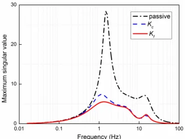
Figure 2-8 Frequency response of sprung mass acceleration and tyre deflection... 24
Figure 2-9 Random response of sprung mass acceleration and tyre dynamic force. ... 24
Figure 2-10 The structure of in-wheel SRM [97]. ... 25
Figure 2-11 The structure of in-wheel PMSM [102]. ... 26
Figure 3-1 Quarter vehicle model with passive suspension and active suspension. ... 41
Figure 3-2 2-DOF quarter car test rig. ... 54
Figure 3-3 Hydraulic power unit, hydraulic actuator and servo valve. ... 55
Figure 3-4 Mounting position of laser displacement sensors... 55
Figure 3-5 Mounting position of acceleration sensors. ... 56
Figure 3-6 Real-time control board. ... 56
Figure 3-7 Power amplifier. ... 57
Figure 3-8 Two computers with LABVIEW software. ... 57
Figure 3-9 Schematic of electromagnetic suspension. ... 57
Figure 3-10 Electromagnetic suspension system and the drive. ... 58
IX
Figure 3-12 Schematic of quarter-car suspension system test rig data acquisition layout.
... 59
Figure 3-13 Sprung mass acceleration responses under 3Hz sinusoidal excitations. ... 60
Figure 3-14 Sprung mass displacement responses under 3Hz sinusoidal excitations. ... 60
Figure 3-15 Unsprung mass displacement responses under 3Hz sinusoidal excitations. 61 Figure 3-16 Active force responses under 3Hz sinusoidal excitations. ... 61
Figure 3-17 Sprung mass acceleration responses under bump excitations. ... 62
Figure 3-18 Sprung mass displacement responses under bump excitations. ... 63
Figure 3-19 Unsprung mass displacement responses under bump excitations. ... 63
Figure 3-20 Sprung mass acceleration responses under random excitations. ... 63
Figure 3-21 Unsprung mass displacement responses under random excitations. ... 64
Figure 3-22 Sprung mass displacement responses under 3.5Hz sinusoidal excitations. Left: with 250kg load. Right: with 290kg load. ... 65
Figure 3-23 Sprung mass acceleration responses under 3.5Hz sinusoidal excitations. Left: with 250kg load. Right: with 290kg load. ... 65
Figure 3-24 Suspension deflection responses under 3.5Hz sinusoidal excitations. Left: with 250kg load. Right: with 290kg load. ... 65
Figure 3-25 Unsprung mass displacement responses under 3.5Hz sinusoidal excitations. Left: with 250kg load. Right: with 290kg load. ... 66
Figure 3-26 Friction estimation under 3.5Hz sinusoidal excitations. Left: with 250kg load. Right: with 290kg load. ... 66
Figure 3-27 Sprung mass acceleration responses under bump road excitation. ... 67
Figure 3-28 Sprung mass displacement responses under bump road excitation. ... 67
Figure 3-29 Unsprung mass displacement responses under bump road excitation. ... 68
Figure 3-30 Friction estimation under bump road excitation... 68
Figure 3-31 Sprung mass acceleration responses under random road excitation. ... 69
Figure 3-32 Sprung mass displacement responses under random road excitation. ... 69
Figure 3-33 Unsprung mass displacement responses under random road excitation. .... 69
Figure 3-34 Friction estimation under random road excitation. ... 70
Figure 4-1 Quarter-car suspension model [10]. ... 73
Figure 4-2 Sprung mass acceleration responses in bump manoeuvre... 79
Figure 4-3 Suspension deflection responses in bump manoeuvre. ... 79
Figure 4-4 Tire dynamic force responses in bump manoeuvre. ... 80
X
Figure 4-6 Motor dynamic force responses in bump manoeuvre. ... 81
Figure 4-7 Actuator forces in bump manoeuvre. ... 81
Figure 4-8 Sprung mass acceleration responses in random manoeuvre. ... 82
Figure 4-9 Suspension deflection responses in random manoeuvre. ... 82
Figure 4-10 Tire dynamic force responses in random manoeuvre. ... 83
Figure 4-11 Motor acceleration responses in random manoeuvre. ... 84
Figure 4-12 Motor dynamic force responses in random manoeuvre. ... 84
Figure 4-13 Actuator forces in random road manoeuvre. ... 84
Figure 5-1 Suspension model of electric vehicle with dynamic-damper-motor [10]. .... 88
Figure 5-2 Structure of dynamic-damping-in-wheel-motor-driven-system [4]. ... 89
Figure 5-3 Bode diagrams of vehicle dynamic responses for increasing unsprung mass. (a) Sprung mass acceleration. (b) Suspension deflection. (c) Tyre dynamic force. ... 89
Figure 5-4 Comparison of frequency responses between different IWM configurations. (a) Sprung mass acceleration. (b) Suspension deflection. (c) Tyre dynamic force. ... 90
Figure 5-5 Structure of the fuzzy reliable H∞ controller ... 95
Figure 5-6 Frequency responses of the passive suspension and active suspensions... 102
Figure 5-7 Vehicle dynamic responses under bump road excitation. (a) Vehicle body acceleration response. (b) Suspension deflection. (c) Actuator force. (d) Tire dynamic force... 102
Figure 5-8 In-wheel motor dynamic responses under bump road excitation. (a) Motor acceleration response. (b) Motor dynamic force. ... 103
Figure 5-9 Bump responses of passive suspension and active suspension with T-S fuzzy controller for different sprung masses. (a) Frequency response. (b) Vehicle body acceleration response. ... 104
Figure 5-10 𝑇𝑇𝑇𝑇𝑇𝑇∞of active suspensions with T-S fuzzy controller and reliable fuzzy controller versus the uncertain parameter. ... 105
Figure 5-11 Frequency responses of active suspensions with T-S fuzzy controller and reliable fuzzy controller. ... 105
Figure 5-12 Body acceleration of active suspensions with T-S fuzzy controller and reliable fuzzy controller under bump road excitation. ... 106
Figure 5-13 Vehicle dynamic responses under random road excitation. (a) Vehicle body acceleration response. (b) Suspension deflection. (c) Actuator force. (d) Tire dynamic force... 107 Figure 5-14 In-wheel motor dynamic responses under random road excitation. (a) Motor
XI
acceleration response. (b) Motor dynamic force. ... 107
Figure 5-15 Body acceleration of active suspensions with T-S fuzzy controller and reliable fuzzy controller under random road excitation. ... 108
Figure 6-1 Random response of sprung mass acceleration and tyre dynamic force. .... 127
Figure 6-2 Frequency response of sprung mass acceleration and tyre deflection... 127
Figure 6-3 Bump response of active suspension with 30% actuator thrust loss ... 130
Figure 6-4 Bump response of active suspension with 60% actuator thrust loss. ... 130
Figure 6-5 Active force. (a) 30% actuator thrust loss. (b) 60% actuator thrust loss. .... 131
Figure 6-6 Bump response of active suspensions with 30% actuator thrust loss and 5ms time delay. ... 132
Figure 6-7 Bump response of active suspensions with 60% actuator thrust loss and 5ms time delay. ... 132
Figure 6-8 Active force. (a) 30% actuator thrust loss. (b) 60% actuator thrust loss. .... 133
Figure 7-1 In-wheel SRM driven electric vehicle suspension model ... 140
Figure 7-2 Quarter vehicle suspension model. (1) Electric vehicle with DVA-SRM. (2) Electric vehicle with conventional in-wheel SRM. (3) Conventional vehicle. ... 140
Figure 7-3 Longitudinal dynamic model... 142
Figure 7-4 Tire longitudinal force ... 143
Figure 7-5 Structure of 8/6 four phase SRM and SRM vertical force. ... 146
Figure 7-6 PSD of road. (a) Different road types. (b) Different forward velocities. ... 148
Figure 7-7 Airgap eccentricity responses to different road types. (a): Time domain. (b): Frequency domain. ... 149
Figure 7-8 SRM vertical force responses to different road types. (a): Time domain. (b): Frequency domain. ... 149
Figure 7-9 Body acceleration responses to different road types. (a): Time domain. (b): Frequency domain. ... 149
Figure 7-10 Tyre deflection responses to different road types. (a): Time domain. (b): Frequency domain. ... 150
Figure 7-11 Airgap eccentricity responses to different vehicle speeds. (a): Time domain. (b): Frequency domain. ... 151
Figure 7-12 Vertical force responses to different vehicle speeds. (a): Time domain. (b): Frequency domain. ... 151
Figure 7-13 Body acceleration responses to different vehicle speeds. (a): Time domain. (b): Frequency domain. ... 151
XII
Figure 7-14 Tyre deflection responses to different vehicle speeds. (a): Time domain. (b):
Frequency domain. ... 152
Figure 7-15 PSDs of vehicle dynamic responses to stochastic road. (a): Body acceleration. (b): Tyre deflection. ... 153
Figure 7-16 PSDs of vehicle dynamic responses to stochastic road. (a): Body acceleration. (b): Tyre deflection. ... 153
Figure 7-17 Control diagram for in-wheel SRM driven electric vehicle ... 160
Figure 7-18 PSDs of vehicle dynamic responses to stochastic road. (a) Sprung mass acceleration. (b) Tyre deflection. ... 161
Figure 7-19 PSDs of SRM dynamic responses to stochastic road. (a) SRM vertical force. (b) Airgap eccentricity. ... 162
Figure 7-20 Vehicle dynamic responses to stochastic road. (a) Sprung mass acceleration. (b) Tyre deflection. ... 163
Figure 7-21 SRM dynamic responses to stochastic road. (a) SRM vertical force. (b) Airgap eccentricity. ... 163
Figure 7-22 Vehicle dynamic responses to bump road excitation. (a) Sprung mass acceleration. (b) Tyre deflection. ... 164
Figure 7-23 SRM dynamic responses to bump road excitation. (a) SRM vertical force. (b) Airgap eccentricity. ... 164
Figure 7-24 Sprung mass acceleration responses to stochastic road... 168
Figure 7-25 Suspension deflection responses to stochastic road. ... 168
Figure 7-26 Tyre deflection responses to stochastic road. ... 169
Figure 7-27 SRM airgap eccentricity responses to stochastic road. ... 169
Figure 7-28 SRM vertical force responses to stochastic road. ... 170
Figure 7-29 SRM motor acceleration responses to stochastic road. ... 170
Figure 7-30 Sprung mass acceleration responses to bump road. ... 171
Figure 7-31 Suspension deflection responses to bump road. ... 171
Figure 7-32 Tyre deflection responses to bump road... 172
Figure 7-33 SRM airgap eccentricity responses to bump road. ... 172
Figure 7-34 SRM vertical force responses to bump road. ... 172
XIII
List of Tables
Table 4-1 Passive, unoptimised and optimised parameters ... 78 Table 4-2 RMS comparison of vehicle dynamic response in random manoeuvre case.. 85 Table 5-1 Suspension parameter ... 89 Table 5-2 RMS comparison of vehicle response under random road excitation. ... 109 Table 5-3 RMS comparison of sprung mass acceleration with different actuator thrust loss. ... 109 Table 6-1 Optimization results of vehicle suspension parameter. ... 127 Table 6-2 RMS comparison of vehicle dynamic responses. ... 127 Table 6-3 The RMS comparison of vehicle dynamic responses under random road excitation ... 134 Table 6-4 The RMS comparison of vehicle dynamic responses with different actuator faults and delays under random road excitation ... 134 Table 7-1 Vehicle suspension parameter values ... 143 Table 7-2 RMS comparison of vehicle dynamic response and SRM dynamic response ... 163 Table 7-3 Vehicle suspension parameter values. ... 167 Table 7-4 RMS comparison of vehicle dynamic response and SRM dynamic response. ... 170
XIV
Abbreviations
IWM In-wheel motor
T-S Takagi-Sugeno
DVA Dynamic vibration absorber
GA Genetic algorithm
SRM Switched reluctance motor
EVs Electric vehicles
DYC Direct yaw moment
AFS Active front wheel steering
FLC Fuzzy logic control
HIS Hydraulically interconnected suspension
ER Electrorheological
MR Magnetorheological
SMC Sliding mode control
PID Proportional integral derivative
P Proportional
PI Proportional integral
PD Proportional derivative
ANFIS Adaptive network-based fuzzy inference system
FTC Fault-tolerant control
EMS Electromagnetic suspension systems
LQ Linear-quadratic
PMA Linear permanent-magnet actuator
LSRA Linear switched reluctance actuator
TCS Traction control systems
ABS Anti-lock brake systems
ESC Electronic stability control
CCC Current chopping control
APC Angle position control
PWM Pulse width modulation
PMSM Permanent magnet synchronous motor
UMP Unbalanced magnetic pull
XV
LQR Linear quadratic regulator
4WID-EV Four-wheel independent drive electric vehicle
4WIS Four-wheel-independent-steering
RB Regenerative braking
ABS Anti-lock braking systems
TPMA Tubular permanent-magnet actuator
ANFWN Adaptive neuro fuzzy wavelet networks
KYP Kalman-Yakubovich-Popov
LPV Linear-parameter-varying
I/O Input-output
BMI Bilinear matrix inequality
ERL Exponential Reaching Law
ICE Internal Combustion Engine
LQG Linear quadratic gaussian
PDC Parallel-distributed compensation
LMIs Linear matrix inequalities
ADM Advanced-dynamic-damper-motor
PSO Particle swarm optimization
RMS Root mean square
MF Magic-formula
1
1.
Introduction
1.1 Background and problem statement
The development of Electric vehicles (EV) has been accelerated in recent years, driven by a number of factors including global warming, heavy dependence on petrol, ever increasing price of fuel, and driving trends. According to the U.S Environmental Protection Agency, electric vehicles convert about 59-62% of the electrical energy from the grid to power at the wheels while conventional gasoline vehicles only convert about 17-21% of the electrical energy [1]. Poor air quality caused by conventional cars in many cities around the word- notably in China - poses a severe health issues for residents. Deployment of EVs could help to reduce the emissions and fine particulate matter (PM2.5) that lead to air pollution, climate change and health problems.
Governments around the world are making efforts to overcome the existing barriers and to accelerate the development of EVs. For example, China has become the most powerful political force driving the globalization of EV technology. According to the “Energy-saving and new-energy vehicle (ENEV) industry development plan (2012–2020)”, China will obtain a production capacity of 2 million and cumulative sales of over 5 million battery EVs and plug-in hybrid EVs by 2020 [2]. When compared with the internal combustion engine (ICE) conventional vehicles, EVs have a wide spectrum of benefits such as enhanced comfort, higher efficiency, lower operating costs, as well as reduced greenhouse gas emission and air quality improvement [3]. These technical advantages drive the increasingly development of electric vehicles.
1.1.1 In Wheel motor Drive
From the viewpoint of electrical and control engineering, EVs, driven by electric motors, have three remarkable advantages: 1) motor torque can be generated fast and accurately 2) electric motors can be installed into each wheel; and 3) motor torque can be precisely measured [4]. Based on the vehicle architecture, the propulsion configuration of electric vehicles can be classified as centralized motor driven and in-wheel motor driven layouts. The second configuration, in which the motors are installed on the wheels and referred to as IWM electric vehicle, has lately proved to be an increasingly popular research area in recent years. The “UOT (University of Tokyo) Electric March II”, proposed by Yoichi Hori group, is a novel four-wheel motored EV [4]. The in-wheel motor driven layout has a number of benefits such as fast motor response, precise torque generation, simplicity
2
and ability to generate forward and reverse torques with no adverse effect on driveshaft stiffness [5, 6]. Since the torque of each wheel can be controlled completely and independently, IWM can also improve the performance of traction control systems (TCS), anti-lock brake systems (ABS), and electronic stability control (ESC) [5]. The IWM technology has been attracting an increasing interest of more companies. For example, Protean Electric has designed an innovative in-wheel electric drive system for hybrid and electric vehicles. Eco-move Q-wheel and Nissan Bladeglider concept [7] (as shown in Figure 1-1) are the two best examples for electric IWM.
Figure 1-1 Nissan Leaf and Nissan Bladeglider [7].
1.1.2 Drawbacks of IWM
However, the deployment of IWM in electric vehicles produces new technological challenges. Attaching the electric motor to the wheel can lead to an increase in the unsprung mass. Some studies show that the mass can be increased by 20 ~ 50% [8]. An increase in the unsprung mass leads to an increase in the response of the frequency ranges around 10 Hz, which shows negative effect on suspension ride comfort performance and road holding ability.
Moreover, the motor bearing, carrying the weight of the vehicle body, can easily wear due to heavy loads and the small gap between the motor rotor and the stator. In-wheel motor vibration and heavy load applied on the motor could easily result in loud noise and bearing wear, reducing the life of the motor bearing. In reality, some degree of rotor eccentricity is always presented in in-wheel SRM due to the motor bearing wear, tolerances introduced during the manufacturing process and static friction especially
3
when the rotor is sitting idle. A relative eccentricity between the stator and rotor of 10% is common. The SRM air-gap eccentricity can result in a residual unbalanced radical force, which can greatly deteriorate the motor performance and vehicle ride comfort. This phenomenon is particularly serious to IWM-EV, because the vertical component of SRM residual unbalanced radical force is applied directly on the vehicle wheels and can change the tire load. The same phenomenon also occurs in in-wheel permanent magnet synchronous motor (PMSM) mounted electric vehicle. The uneven magnetic gap of PMSM may lead to unbalanced electromagnetic force, which has negative effect on vehicle ride performance and road-holding ability. These trends clearly show the need of active suspension in electric vehicles, which can contribute to enhanced vehicle ride comfort and dynamic performance.
Figure 1-2 Bridgestone’s Dynamic-Damping In-wheel Motor Drive System [9].
Due to the many advantages of wheel motors, several companies are working on in-wheel motor designs to minimize these adverse effects on IWM to obtain a better vibration isolation performance. Bridgestone proposes the so-called dynamic-damping-in-wheel-motor-driven-system [9], that suspends shaft-less direct-drive motor, isolating it from the unsprung mass. The motor is designed as a vibration absorber that could offset the road vibration input, as shown in Figure 1-2. The system is shown to have the potential to improve ride quality and road-holding performance. Tyre contact force fluctuations in conventional EVs and IMW-EVs with dynamic damping are compared in [10]. Michelin Company proposes active wheel system for battery EV or fuel-cell EV, as shown in
Figure 1-3, which consists of an electric motor that drives the wheel, a braking system
4
wheel, while the active suspension system is utilised to enhance ride performance, handling stability and passenger safety. The e-Corner proposed by Siemens company is a combination of an active suspension system, an electric motor, as well as an electronic wedge brake-by-wire system mounted in the wheel and hub assembly [12], as shown in
Figure 1-4 . The use of active suspension in these systems could possibly reduce the
adverse effects of increased vehicle unsprung mass. Since passenger health and safety present an ever-increasing demand in the active suspension design. Therefore, research focus on the electric vehicle suspension system related to the comfort, and safety should be investigated. Possible methods to improve the ride comfort and safety of electric vehicle equipped with in-wheel motor are using an active suspension system or optimization of the passive suspension. Active suspension system is necessary for the successful implementation of IWM technology in future vehicles.
Figure 1-3 Michelin Active Wheel System [11].
Figure 1-4 eCorner. (1) Wheel rim (2) Wheel hub motor (3) Electronic wedge brake (4) Active suspension (5) Electronic steering [12].
5
1.1.3 Active Suspension for IWM
Vehicle suspension system, linking vehicle body and its wheels, is considered to be one of the most important part of vehicle, and contributes to the vehicle ride, handling and safety analysis. The design requirement of suspension system should satisfy conflicting requirements between ride comfort and handling stability. For example, a “hard” suspension has good vehicle handling stability, but it will cause harsh ride. A “soft” suspension will yield a more comfortable ride, but the stability of the vehicle is significantly reduced. Three kinds of vehicle suspension system, such as passive suspension system, semi-active suspension system and active suspension system, have been researched so far. Hydraulically interconnected suspension have been also researched to overcome the ride-handling compromise. Over the past decades, research in this area has been focused on controlled suspension systems such as semi-active suspension system with adjustable stiffness or damping parameters and active suspension system, which could make the optimal feedback control according to road conditions and driving conditions. A novel active suspension overcoming the ride-handling compromise for the hybrid and electric vehicle is a trend in the development of future suspensions. Compared to passive and active hydraulic suspension systems, the active electromagnetic suspension system is more suitable for the electric vehicles since it offers accurate force control, fast dynamic response and simple mechanical construction. Linear electromagnetic actuator and rotary electromagnetic actuator can be applied in the active electromagnetic suspension systems. Mechanical mechanisms such as ball-screw and rack–pinion are often utilised to convert the linear suspension motion into rotary motion. The Bose suspension system, as shown in Figure 1-5, uses a linear electromagnetic motor and an amplifier at each wheel in lieu of a conventional shock-and-spring setup [13]. This kind of suspension system can prevent the vehicle body motion while accelerating, braking and cornering, giving the driver a comfort ride. Ka Wai Eric Cheng et al. propose a novel active electromagnetic suspension system by adopting linear switched reluctance actuator. The proposed linear switched reluctance actuator is simple, low cost, as well as reliable and high performance, which offers a potential alternative to permanent-magnetic actuators [14-16]. Linear permanent-magnet actuator (PMA) is the most popular type of electric actuator applied to active suspension system. B.L.J. Gysene et al. propose an active electromagnetic suspension by incorporating brushless tubular PMA in parallel with a spring [17]. The design, control strategy, power consumption of
6
the direct-drive electromagnetic active suspension are particularly investigated in [17, 18].
Figure 1-5 Bose suspension system [13].
Various control methods such as fuzzy logic control [19, 20], optimal control [21], neural network control, linear quadratic regulator control, sliding control [22], preview control
[23] and H∞ control [24-27] are proposed for active suspension system to deal with the
conflicting requirements between ride comfort, suspension deflection and road holding.
Among these control algorithms, H∞ control is shown to overcome the trade-off and offer
a favourable performance. According to the literature, the H∞ control strategy can deal
with complexities such as parameter uncertainties, actuator faults, damper time delay and external disturbance. It is assumed that all the components of the suspension system are in normal working conditions when we design the controller. In practice, Failures can occur in actuators, sensors, controllers, or in the system, which could worsen the suspension performance. Fault detection and fault tolerant control methods are utilized for active suspension systems to detect the fault and ensure a better performance of the controlled suspension system [28-30]. Furthermore, the actuator delay occurred due to the pneumatic and hydraulic characteristics of the actuators or the acquisition and transmission of data from sensors to the controller, may damage the control performances and even result in control system instability if not considered in the controller deign. Various controller design schemes are proposed for active suspension system with actuator delay [31, 32]. However, nonlinear problem of suspension is neglected in most of the previous suspension control researches. Model uncertainties such as suspension sprung, and unstrung mass variation should be taken into consideration in the active
7
suspension design. Nonlinear spring and piece-wise linear damper dynamic also should be considered. T-S fuzzy approach [33]and linear-parameter-varying technique [34, 35] are two effective methods to deal with the system uncertainties and nonlinearities. External disturbance such as system friction, system uncertainties and external interference have negative effect on control system performance and stability. Control methods based on the disturbance absorber can be utilized to estimate and compensate the influence of external disturbance [36-38].
1.2 Aims, Contributions and Publications of Thesis
1.2.1 Aims
The primary aim of this thesis is to investigate effective methods to provide active suspension in electric cars in the presence of systems friction, system uncertainties, sprung mass variation, and actuator delays and faults. The realised active suspension system improves the vehicle performance and road holding stability under different road conditions. In pursuit of the aim of the project, several objectives are pursued and achieved. Firstly, we have developed friction observer-based controllers for active suspension system to deal with the issues on system friction. Experimental validation of the proposed controllers is conducted on the test rig. As mentioned before, active suspension system or optimization of the passive suspension are two possible methods to improve the ride comfort and safety of electric vehicle equipped with in-wheel motor. Multi-objective parameter optimization is proposed for active suspension of in-wheel motor mounted electric vehicle based on genetic algorithm. Furthermore, several active suspension control methods are developed for active suspension system of in-wheel motor driven electric vehicle vehicles in the presence of sprung mass variation, actuator faults, time delay and control input constraints. The methods developed in this thesis can effectively improve vehicle ride comfort, simultaneously satisfying the performance constraints such as road holding, suspension stroke, dynamic load applied on the bearings and actuator limitation. We have also studied the active suspension control of electric vehicle mounted switched reluctance motor. The coupling effect between road excitation and an in-wheel switched reluctance motor on vehicle ride comfort is also investigated. 1.2.2 Contributions
8
1. A comprehensive review of the literature relating to passive suspension system,
controlled suspension and regenerative suspension, outlining the disadvantage of IWM is conducted, and the active suspension methods applied to IWM-EVs in previous work are identified.
2. A quarter-car suspension test rig for the active suspension control research is
developed. The experimental rig is used to examine and validate the performance of the proposed control methods and their validity.
3. A fault-tolerant H∞ controller based on friction compensation is proposed for
active suspension system considering the parameter uncertainties, actuator faults, as well as actuator time delay and system friction. Experimental validation of the proposed control was conducted on the test rig. The proposed control method guarantees asymptotic stability and significantly improves the vehicle ride performance under actuator faults and constant delay. A friction observer-based T-S fuzzy controller is proposed for active suspension considering the sprung mass variation and system friction. The experimental results demonstrate the effectiveness of the proposed controller in improving suspension performance in spite of sprung mass variation and system friction.
4. Multi-objective parameter optimization for active suspension of in-wheel motor
mounted electric vehicle based on genetic algorithm is proposed to suppress the sprung mass vibration, motor vibration as well as improving ride comfort, suspension deflection and road holding stability. The quarter-car active suspension with in-wheel motor served as dynamic vibration absorber is developed, and the motor parameters, suspension parameters and active controller are optimized based on the genetic algorithm.
5. A fault-tolerant fuzzy H∞ controller for active suspension of in-wheel motor
driven electric vehicles in the presence of sprung mass variation, actuator faults and control input constraints is proposed. The T-S fuzzy suspension model is developed to
deal with sprung mass variation. The H∞ performance of the proposed controller is
derived as linear matrix inequalities (LMIs) which are solved efficiently by means of
MATLAB LMI Toolbox. The reliable fuzzy H∞ controller achieves a significantly
enhanced closed-loop H∞ performance and suspension performance.
6. A robust output feedback H∞ controller is designed for active suspension system
of in-wheel motor driven electric vehicles in the presence of actuator faults and time delays. Simulation results show that the proposed controllers could guarantee the
9
performance constraints such as road holding, suspension stroke, dynamic load applied on the bearings and actuator limitation.
7. Coupling effects between road excitation and in wheel switched reluctance motor
on electric vehicle ride comfort are analysed. To supress SRM vibration and to prolong the SRM lifespan, while at the same time improving vehicle ride comfort, a hybrid control method including output feedback controller and SRM controller is proposed to reduce the sprung mass acceleration and the motor air-gap eccentricity. Furthermore, a state
feedback H∞ controller is developed for in-wheel switched reluctance motor driven
electric vehicle with dynamic vibration absorber to further enhance vehicle ride performance. Combined control methods of CCC and PWM are used to improve SRM performance. Simulation results under bump road excitation and random road excitation demonstrate the effectiveness of DVA structure active suspension system with proposed control method in enhancing suspension and motor performance.
1.2.3 Publications
The outcomes produced in the thesis are disseminated through the following publications:
• Shao, X., Naghdy, F., and Du, H., "Active Suspension Control of Electric Vehicle
Driven by Switched Reluctance Motor Based on Vibration Absorbing Structure," SAE Technical Paper 2018-01-1401, 2018.
• Qin, Yechen, Chenchen He, Xinxin Shao, Haiping Du, Changle Xiang, and
Mingming Dong. "Vibration mitigation for in-wheel switched reluctance motor driven electric vehicle with dynamic vibration absorbing structures." Journal of Sound and Vibration 419 (2018): 249-267.
• Shao, Xinxin, Fazel Naghdy, and Haiping Du. "Enhanced ride performance of
electric vehicle suspension system based on genetic algorithm optimization." In Electrical Machines and Systems (ICEMS), 2017 20th International Conference on, pp. 1-6. IEEE, 2017.
• Shao, Xinxin, Fazel Naghdy, and Haiping Du. "Reliable fuzzy H∞ control for
active suspension of in-wheel motor driven electric vehicles with dynamic damping." Mechanical Systems and Signal Processing 87 (2017): 365-383.
10
• Shao, Xinxin, Haiping Du, and Fazel Naghdy. Enhanced Vehicle Handling and
Ride through Anti-Pitch Anti-Roll Hydraulically Interconnected Suspension. No. 2016-01-1561. SAE Technical Paper, 2016.
• Shao, Xinxin, Fazel Naghdy, and Haiping Du, Hongyi Li, “Output feedback H∞
control for active suspension of in-wheel motor driven electric vehicle with control faults and input delay”, ISA Transactions, under review.
• Shao, Xinxin, Fazel Naghdy, Haiping Du, Yechen Qin, “Coupling effect between
road excitation and an in-wheel switched reluctance motor on vehicle ride comfort and active suspension control”. Journal of Sound and Vibration, under review.
1.3 Outline of the thesis
This thesiswork show novel methods that active control can be applied to suspension to
improve conventional and electric vehicle ride comfort and safety. Initially, we propose some control methods for active suspension system of conventional vehicles. Experimental validation of the proposed control is conducted on the test rig. Then the studies are focused on the electric vehicle suspension system. Several optimization algorithms and control methods are proposed for active suspension system of electric vehicle driven by in-wheel motor to improve vehicle ride comfort and safety, as outlined in chapters 4, chapter 5 and chapter 6. Finally, the active suspension control of electric vehicle with mounted switched reluctance motor is investigated. Coupling effect between road excitation and an in-wheel switched reluctance motor on vehicle ride comfort is also investigated. This thesis is organized into eight chapters as follows:
Chapter 1 - Introduction. This chapter provides a brief background and motivation for the current study, outlines the objective and contribution of the project and describes the structure of the thesis.
Chapter 2 - Literature review. A comprehensive review of vehicle suspension systems including passive suspension semi-active suspension and active suspension is conducted. A review of the literature on in-wheel motor electric vehicle suspension regenerative suspension is also covered. Furthermore, an overview of active suspension control algorithms is provided.
Chapter 3 - Experimental validation of robust H∞ controller for active suspension with
friction estimation. In this chapter, a quarter vehicle experiment test rig setup is described.
11
vehicle suspension system and experimental validation is conducted. Experimental validation of friction-observer based T-S fuzzy controller for active suspension is also reported in this chapter.
Chapter 4 - Active suspension control using genetic algorithm in in-wheel mounted vehicle. In this chapter, a quarter vehicle suspension model with a suspended motor and active suspension is established. Multi-objective parameter optimization for active suspension of electric vehicle with in-wheel motor based on genetic algorithm is presented. Genetic algorithm is used to optimize the vehicle suspension parameter and optimal control force. Simulation validation and conclusions are provided.
Chapter 5 - Reliable fuzzy H∞ control for active suspension of in-wheel motor driven
electric vehicle with dynamic damping. An electric vehicle suspension model with an
“advanced-dynamic-damper-motor” is developed. A fault-tolerant fuzzy H∞ control
design approach for active suspension of in-wheel motor driven electric vehicles in the presence of sprung mass variation, actuator faults and control input constraints is proposed. Simulation validation and conclusions are provided.
Chapter 6 - Output feedback H∞ control for active suspension with control faults and input
delay in in-wheel motor mounted vehicle. Electric vehicle with suspended motor served as dynamic vibration absorber is developed. Particle swarm optimization is used to optimize the suspended motor parameter. A dynamic feedback controller considering actuator faults and time delay are designed for vehicle suspension system. Simulation validations of the proposed control algorithm are provided.
Chapter 7 - Coupling effect between road excitation and an in-wheel switched reluctance motor on vehicle ride comfort and active suspension control. Firstly, coupling effects of road type and switched reluctance motor on vehicle ride comfort characteristic are
illustrated. A hybrid control method including output feedback H∞ control and switched
reluctance motor control for active suspension and simulation validation are presented.
Furthermore, a state feedback H∞ controller combined with switched reluctance motor
controller is proposed for active suspension with dynamic vibration absorber, and simulation results under random and bump road excitation are also provided.
Chapter 8 - Conclusion and future work. In this chapter, the outcomes of the thesis are critically discussed, and some conclusions are drawn, the future extension of the work is also discussed in this chapter.
12
2.
Literature Review
2.1 Introduction
Electric vehicles (EVs) have various remarkable benefits such as energy source flexibility and environment friendliness when compared to conventional vehicles. They can also produce sufficient driving performance and efficiency using advanced electric motors and battery technologies. The mounting of the electric drives on the wheels, known as “in-wheel motor”, has attracted increasing research interests recently due to the numerous advantages it offers. However, IWM technology has major drawbacks such as increased unsprung mass, air-gap eccentricity of motor and motor wear, which significantly deteriorate the ride comfort performance and road holding stability.
Suspension systems of conventional vehicles have been extensively researched during the past decades in terms of, control strategy, structural design and dynamic analysis [39]. A review on the effect of IWM on vehicle ride, handling and stability performance have been reported. Dynamic analysis and control strategies of EV suspension system related to the ride, yaw stability and lateral motion stability are also investigated. Active suspension system is essential for successful implementation of IWM technology. Active suspension control methods are utilized to eliminate the increase in vehicle body acceleration and dynamic wheel load caused by the IWM subjected to system uncertainties, suspension nonlinearities and external disturbances.
In this chapter, a comprehensive review of suspension systems of EVs with IWM is initially carried out. The focus is particularly on the methods proposed to improve the impact of IWM on EV ride comfort, handling stability, and energy regeneration. In terms of vehicle ride comfort, issues associated with IWM such as increased unsprung mass, air-gap eccentricity, unbalanced vertical force, motor vibration and motor wear could significantly influence the vehicle performance. Active suspension control and suspension optimization are two effective ways to cope with these issues. In terms of handling stability, direct yaw moment (DYC) and active front wheel steering (AFS) are two effective ways to enhance the handling and stability performance of four-wheel independent drive EVs. Moreover, active suspension systems including electrohydraulic active suspension and electromagnetic active suspension can improve handling stability by preventing vehicle roll motion and pitch motion during steering and braking, as well as eliminating road excitation. Hence increasing vehicle ride comfort and safety, have
13
been explored by many researches. Various control methods such as fuzzy logic control
(FLC), optimal control, robust H∞ control, as well as sliding control and preview control,
which could cope with suspension system nonlinearities, external disturbance and uncertainties, are reviewed. Active suspension systems require a large amount of energy, which limits their implementations in EVs. This has attracted a significant number of studies on regenerative suspension systems in recent years with the aim of harvesting energy from suspension vibration, as well as reducing the vehicle vibration. Furthermore, the regenerative suspension system applied in electric vehicle will be a trend in the future. Different types of regenerative suspension system including hydraulic regenerative suspension, electromagnetic regenerative suspension as well as self-powered magnetorheological damper are also reviewed in this chapter.
2.2 Vehicle suspension system
Vehicle wheels and body are linked using suspension systems, which have three basic elements such as spring and shock absorbers and linkages that connect a vehicle to its wheels. Apart from its basic purpose of isolating the vehicle body from the road roughness and vibration, the suspension prevents the vehicle body from rolling and keeps the tires in contact with the road [40]. Moreover, it also can contribute to the vehicle's road holding/handling for active safety and driving stability, and keep vehicle passengers comfortable. Suspension systems can be classified into passive, semi-active and active suspensions.
2.2.1 Passive suspension
Passive suspension has the traditional springs and dampers, which cannot be changed during different road excitations and manoeuvres. This has many advantages compared to the controlled suspension such as simplicity, high reliability, low cost and zero energy consumption. Vehicle dynamic response is usually assessed under a random road profile described by Gaussian white noise or, bump road profile. Vehicle ride comfort is represented by the vehicle body acceleration as specified in the ISO 2631. The suspension deflection can be utilised to enforce the suspension displacement constraint, which prevents the suspension from reaching its travel limit for preventing ride deterioration and mechanical structural damage. Road holding stability can be generally quantified by tyre deflection. Parameters of a passive suspension system are optimized to suppress vehicle vibration based on genetic algorithm in [41]. Vehicle dynamics are influenced by random road excitation, vehicle velocity and system parameters. Optimum design of a vehicle
14
passive suspension system under actual random road excitation is presented in [42]. The fundamental problems associated with passive suspension design of heavy road vehicle are studied in [43]. Some performance criteria such as ride, suspension working space, infrastructure damage, rollover stability, and yaw stability are considered when the dynamic properties of heavy vehicle suspension systems are assessed.
Passive anti-roll systems such as anti-roll torsional bar can be used to improve vehicles stability factor, in particular, its anti-roll ability. Spring interconnections between left and right wheels in the form of anti-roll bars has the advantages of improving relatively higher roll stiffness, but they can increase the stiffness in vehicle articulation, which is undesirable in terms of the vehicle road-holding ability and ride comfort performance. Cole [44] suggested that an anti-roll bar applied on the vehicle can result in less road damage than springs alone, and an independent suspension causes less road damage than a rigid axle suspension. A number of studies on alternative passive suspension such as roll-plane interconnected suspension system and pitch-plane interconnected suspension is conducted in the past decades, and the passive interconnected suspension system can optimize the conflicting performance in terms of vehicle ride comfort and handling stability [45].
In an interconnected suspension system, the displacement at one-wheel station can generate forces at other wheel stations, which is realized through mechanical or fluidic. This kind of suspension system has the potential of overcoming the ride comfort-handling stability compromise [46]. Passive interconnected suspension systems have received a significant number of attention recently. Cao et al. provide a comprehensive investigation of interconnected pneumatic suspensions in [45, 47, 48]. Apart from hydro-pneumatic suspensions, the hydraulically interconnected suspensions have also attracted many attentions in the past decade. Zhang et al. [46, 49] propose a hydraulically interconnected suspension (HIS) system, which typically consists of a single- or double-acting hydraulic cylinder at each wheel station, replacing the conventional shock absorber. Modelling and model analysis of tri-axle trucks with passive HIS is proposed by Ding [50]. The Schematic diagram of anti-roll HIS proposed by Zhang et al. [49, 51] is shown in Figure 2-1. From the figure we can see the four cylinders are interconnected by hydraulic circuits, and hydraulic accumulators, damper valves, flexible hoses, and pipelines are comprised in each circuit. Simulation study and experimental validation of an SUV fitted with a HIS under different steering maneuvers is presented in [51, 52],
15
respectively. The simulation experiment results indicate that this kind of suspension has been also recognized to achieve a desired vehicle dynamic performance at roll motion-mode and prevent vehicle roll over.
Figure 2-1 Anti-roll HIS. (a) Schematic diagram of the anti-roll HIS. (b) The assembled anti-roll HIS system [49, 51].
2.2.2 Semi-active suspension system
Compared with passive suspension, the controlled suspension system can make the optimal feedback control in accordance with different road excitations and driving conditions, which can improve vehicle ride comfort and handling stability. Different types of semi-active and active suspensions are discussed and reviewed. Karnopp and Crosby [53] first introduced the concept of semi-active suspension system in the early 1970s by presenting the skyhook algorithm to enhance the vehicle ride performance. The semi-active suspension system is a substitution of the semi-active suspension and has many advantages over it such as energy efficiently, simplicity and cost saving. Usually, in a semi-active suspension system, the actuator is replaced by a variable damper that works in parallel with a spring. The damping force is regulated by modifying the orifice area in the oil-filled damper, thus altering the resistance to fluid flow. The variation of damping can be obtained by introducing mechanisms such as electrorheological (ER) damper and magnetorheological (MR) dampers [54].
2.2.2.1ER based semi-active suspension
16
one of the most effective method in improving vehicle ride comfort and handling stability. ER fluid has a quick response feature to an electric field and in consequence a wide bandwidth of control. A continuously variable ER damper, proposed by Choi et al. [55, 56], achieved the desired damping force by applying a skyhook controller. Furthermore, a field test of the semi-active ER suspension system associated with four independent skyhook controllers was conducted to demonstrate its effectiveness [57]. The configuration of the ER shock absorber proposed in [58] is shown in Figure 2-2. Choi et al. [59] proposed a robust sliding mode controller to evaluate control performance of semi-active ER seat suspension system. A sliding mode control (SMC) is propose for ER suspension system based on full vehicle model through hardware-in-the-loop simulation in [60]. Based on this work, another control method known as moving SMC, was proposed to apply for uncertain control system. Sung [61] proposed a fuzzy moving sliding mode controller, and then experimentally realized it on a quarter vehicle model with an ER suspension system. These studies indicate that the ER suspension system associated with proposed control strategy can effectively improve ride comfort of a vehicle.
Figure 2-2 ER damper. (a) Schematic configuration. (b) Photograph of ER damper [58]. 2.2.2.2MR fluid based semi-active suspension
17
Figure 2-3 shows the schematic configuration of the MR damper, proposed by S.-B. Choi [62]. A cylindrical MR damper is proposed and manufactured based on Bingham model of a MR fluid in [62]. Several models are proposed to describe the characteristic of the MR damper such as Bouc-Wen hysteresis model, algebraic model, polynomial model, neural network model and LuGre friction model. A semi-active sky-hook control for MR damper suspension system with is presented in [63]. Bouc–Wen model is utilized to characterize the dynamical behaviour of the MR damper. A nonlinear adaptive controller of the semi-active MR damper suspension system with model parameters uncertainties is proposed in [64]. Modified dynamic LuGre friction model is adopted to analyse the performance of MR damper, and experiments are conducted to identify the parameter of MR damper. A new modified algebraic model is presented in [65] to characterize the performance of the MR damper. Algebraic model is preferable for MR damper due to its low computational expenses when compared to differential Bouc-Wen’s model which needs high computing intensive. Two different controllers, system controller and damper controller are designed in this study. Furthermore, a polynomial model is proposed in [66] to characterize the dynamical behaviour of the MR damper using experimental data. A
static output feedback H∞ controller is proposed based on a quarter car suspension model
to meet the three main vehicle control objectives of ride comfort, road holding, and suspension deflection.
Various control methods such as sky-hook control, model-following SMC, nonlinear
adaptive control, fuzzy-proportional integral derivative (PID) control and H∞ control are
deployed to construct the semi-active controller for the MR dampers suspension system. A variable stiffness and damping suspension system, which obtains variable stiffness and damping through a MR damper is presented in [67]. Two controllers such as fuzzy logic direct yaw moment controller and variable stiffness and damping on/off controller are proposed for the suspension system. A self-tuning adaptive PID control strategy for vehicle semi-active suspension system is presented in [68], Four basic controller are developed in the paper, such as PID, proportional (P) only, as well as proportional integral (PI) and proportional derivative (PD). Panos [69] proposes a clipped-optimal control method for semi-active suspension system, which can be capable of optimizing the vehicle ride and handling behaviour. A semi-active SMC algorithm for MR damper suspension systems is presented in [70]. The proposed controller doesn’t require measurement of the damper force, and it also maintains the sliding mode and achieves
18
high robustness object to model parameters uncertainties and road disturbances. Neural network control for semi-active MR damper suspension is presented in [71]. The MR damper reveals nonlinear hysteresis between its relative velocity and output force, and the state transition from fluid to semi-solid or solid also present extra nonlinear stiffness of MR damper. A fuzzy-PID control algorithm for semi-active MR damper suspension system is presented in [72], and an adaptive network-based fuzzy inference system (ANFIS) model is used to describe the behaviour of magnetorheological damper. Adaptive semi-active controller for quarter-vehicle MR damper suspension based on Bouc–Wen model is presented in [73]. The controller contains a parameter adaptive method estimating the model parameters uncertainties, an observer estimating the damper hysteresis internal state and an adaptive state-feedback control algorithm guaranteeing the suspension system stabilization.
Figure 2-3 Schematic configuration of the MR damper [62]. 2.2.3 Active suspension system
2.2.3.1Electrohydraulic suspension system
Electrohydraulic systems are typically selected as the actuators to produce the active forces to isolate the vibrations from road profile in an active suspension design. However, highly nonlinear behaviour of electrohydraulic systems makes it hard to construct the ideal control algorithm. The schematic of the electrohydraulic actuator is shown in Figure 2-4. PID controller for nonlinear half-vehicle electrohydraulic suspension system is presented in [74]. An outer loop for suspension travel feedback control and an inner loop for PID hydraulic active force feedback control are used in this paper. A T-S fuzzy model
19
approach based fuzzy static output feedback control algorithm for electrohydraulic active suspensions is presented in [75]. Haiping Du and Nong Zhang present a T-S fuzzy controller for electrohydraulic active vehicle suspensions taking actuator nonlinear characteristic, control input constraints and sprung mass variation into account in [33]. A
H∞ controller based on adaptive robust control design approach is proposed for full-car
electrohydraulic active suspension to supress road disturbance and increase the ride performance of active suspension systems in [27]. Adaptive PID-sliding-mode fault-tolerant control (FTC) method is presented for active suspension system to cope with the control faults and system uncertainties based on full-vehicle model, and an adaptive PID controller is employed for each of the electrohydraulic actuator [76]. A constrained adaptive back-stepping strategy is proposed for half-car active suspension with electrohydraulic to prevent both the pitch and vertical motions, despite the presence of parameters uncertainties and highly nonlinear actuators [77]. Two control loop arrangements including an outer loop for PID suspension parameters control and an inner loop for PID hydraulic actuator force control are proposed in [78] for a half nonlinear active suspension system model.
An active HIS can be built by integrating some active components such as electronic valves and pressure control power unit. The pressure control unit, which shown in Figure 2-5, can estimates the roll angle and controls the circuits’ pressures to generate an anti-roll moment. Theoretically, the interconnected suspension can de-couple four vehicle body-wheel motion-modes such as roll, bounce, pitch and warp. Lifu Wang [79] proposes the motion-mode energy method, which can decompose vehicle motion into a set of uncoupled vehicle motion-modes. Then Du [80] proposes switched control of vehicle HIS by actively switching the interconnection configuration of suspension in terms of vehicle body motion-modes. Shao [81] presents a fuzzy control of HIS with configuration switching based on the detected dominant vehicle body motion-mode. The results show that the designed controllers can effectively reduce the pitch motion and prevent rollover. Quang Lam [82] propose a fuzzy control method for an active HIS based on a sport utility vehicle, and experimental validation is conducted to verify the effectiveness of proposed
controller. An H∞ control strategy is employed for a roll-plane active HIS to control
vehicle roll motion in [83], and the effectiveness of the proposed H∞ control method is
20
Figure 2-4 Schematic of the electrohydraulic actuator [27].
Figure 2-5 Photo of the pressure control unit [83]. 2.2.3.2Electromagnetic suspension system
A review of electromagnetic suspension systems (EMS) applied on passenger vehicles is conducted in [84]. The electromagnetic suspension system can be general applied in many applications for example electric vehicle, vibration isolation, as well as energy harvesting and high-speed maglev passenger trains. A great deal of control methods such as SMC
[85], linear-quadratic (LQ) control, robust H∞ control [86] and fault tolerant control [87]
are used for active EMS system in recent years. A fuzzy state feedback control strategy for electromagnetic suspension systems based on T-S fuzzy modelling technique is proposed in [88], in which the fuzzy controller is proposed with nonparallel distributed compensation control law, can be solved using linear matrix inequalities methods. P. K. Sinha [86] proposes a nonlinear state and output feedback controllers for magnetically levitated vehicles with electromagnetic suspension systems. A SMC algorithm is designed for an active EMS in [85] , in which the performance of active EMS based on the proposed SMC method is much better than those of the active suspension that utilizing the LQ control. A fault tolerant controller is proposed for EMS systems that exhibit


![Figure 5-1 Suspension model of electric vehicle with dynamic-damper-motor [10].](https://thumb-us.123doks.com/thumbv2/123dok_us/1441817.2693076/105.893.234.732.910.1111/figure-suspension-model-electric-vehicle-dynamic-damper-motor.webp)
![Figure 5-2 Structure of dynamic-damping-in-wheel-motor-driven-system [4].](https://thumb-us.123doks.com/thumbv2/123dok_us/1441817.2693076/106.893.210.730.148.378/figure-structure-dynamic-damping-wheel-motor-driven-system.webp)