HD Color Video Camera
A-E99-100-11 (1)Table of Contents
VISCA RS-232C/RS-422 Commands ... 3
Overview of VISCA ... 3
VISCA Communication Specifications ... 4
VISCA Device Setting Command ... 6
VISCA Command/ACK Protocol ... 7
VISCA Camera-Issued Messages ... 8
BRC-H900 Commands ... 9
BRC-H900 Command List (1/5)
... 9
BRC-H900 Command List (2/5)
... 10
BRC-H900 Command List (3/5)
... 11
BRC-H900 Command List (4/5)
... 12
BRC-H900 Command List (5/5)
... 13
BRC-H900 Inquiry Command List (1/3)
... 14
BRC-H900 Inquiry Command List (2/3)
... 15
BRC-H900 Inquiry Command List (3/3)
... 16
BRC-H900 Block Inquiry Command List ... 17
VISCA Command Setting Values ... 25
Pan/Tilt Status Code List ... 27
Memory Function (Inquiry Commands) ... 28
VISCA
1)
RS-232C/RS-422 Commands
Use of RS-232C/RS-422 control software based upon
this command list may cause malfunction or damage to
hardware and software. Sony Corporation is not liable
for any such damage.
Overview of VISCA
In VISCA, the side outputting commands, for example,
a computer, is called the controller, while the side
receiving the commands, such as a BRC-H900, is called
the peripheral device. The BRC-H900 serves as a
peripheral device in VISCA. In VISCA, up to seven
peripheral devices like the BRC-H900 can be connected
to one controller using communication conforming to
the 232C/422 standard. The parameters of
RS-232C/RS-422 are as follows.
• Communication speed: 9600 bps/38400 bps
• Data bits : 8
• Start bit : 1
• Stop bit : 1
• Non parity
Flow control using XON/XOFF and RTS/CTS, etc., is
not supported.
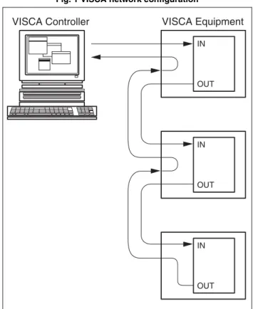
Peripheral devices are connected in a daisy chain. As
shown in Fig. 1, the actual internal connection is a
one-direction ring, so that messages return to the controller
via the peripheral devices. The devices on the network
are assigned addresses.
The address of the controller is fixed at 0.
The addresses of peripheral devices are as follows.
When the camera address selector is set to 0
(automatic setting mode)
The peripheral devices are assigned to the addresses, 1,
2, 3… in the connected order, starting from the one
connected nearest to the controller. These addresses are
set when the controller sends address commands during
initialization of the network.
When the camera address selector is set to 1
through 7 (manual setting mode)
The addresses of the peripheral devices will be set to the
pre-selected numbers. Within a single system, the same
Note
In the same network, all the camera address selectors
should be set to “0” (automatic setting) or all the
selectors should be manually set to “1” to “7”. Do not
mix the automatic and manual settings.
Each VISCA equipment has VISCA IN and VISCA
OUT connectors.
Set the DTR input (the S output of the controller) of
VISCA IN to H when controlling VISCA equipment
from the controller.
Fig. 1 VISCA network configuration
VISCA Equipment IN OUT IN OUT IN OUT VISCA Controller
VISCA Communication
Specifications
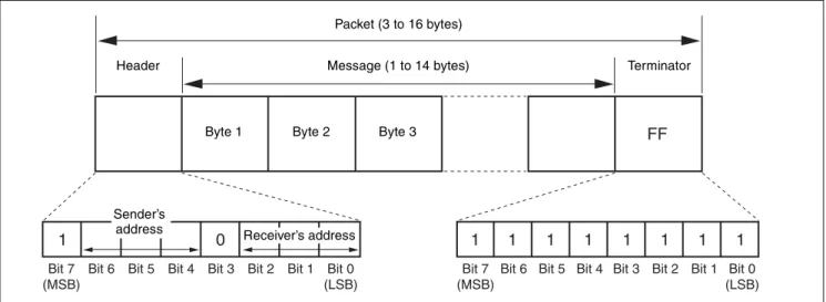
VISCA packet structure
The basic unit of VISCA communication is called a
packet (Fig. 2). The first byte of the packet is called the
header and comprises the sender’s and receiver’s
addresses. For example, the header of the packet sent to
the BRC-H900 assigned address 1 from the controller
(address 0) is 81H in hexadecimal. The packet sent to the
BRC-H900 assigned address 2 is 82H. In the command
list, as the header is 8X, input the address of the
BRC-H900 to X. The header of the reply packet from the
BRC-H900 assigned address 1 is 90H. The packet from
the BRC-H900 assigned address 2 is A0H.
Some of the setting commands for BRC-H900 can be
sent to all devices at one time (broadcast). In the case of
broadcast, the header should be 88H in hexadecimal.
When the terminator is FFH, it signifies the end of the
packet.
Fig. 2 Packet structure
Note
Fig. 2 shows the packet structure, while Fig. 3 shows the
actual waveform. Data flow will take place with the LSB
first.
Fig. 3 Actual waveform for 1 byte.
Timing Chart
As VISCA command processing can only be carried out
a maximum of one time in a Vertical (V*) cycle, it takes
maximum 4V-cycle time for an ACK/Completion to be
returned.
If the Command and ACK/Completion communication
time is shorter than 1V-cycle time, a command can be
received at every 1V cycle. From this point, if two or
more commands are to be sent successively, wait for a
reply command (an ACK or error message for a general
command, and an inquiry packet for an inquiry
command) of the previous command to be received
before sending the next command.
Bit 7 (MSB)
Bit 6 Bit 5 Bit 4 Bit 3 Bit 2 Bit 1 Bit 0 (LSB)
1 0
FF
Bit 7 (MSB)
Bit 6 Bit 5 Bit 4 Bit 3 Bit 2 Bit 1 Bit 0 (LSB)
1 1 1 1 1 1 1 1
Packet (3 to 16 bytes)
Message (1 to 14 bytes)
Byte 1 Byte 2 Byte 3
Sender’s
address Receiver’s address
Header Terminator
Bit 0 Bit 1 Bit 2 Bit 3 Bit 4 Bit 5
(LSB) (MSB) Bit 6 Bit 7 1 byte Start bit Stop bit. Command Within 4V RxD TxD ACK Completion Within 4V RxD Inquiry Packet Command
General commands
Inquiry commands
Command and inquiry
•
Command
Sends operational commands to the BRC-H900.
•
Inquiry
Used for inquiring about the current state of the
BRC-H900.
Command Packet Note
Inquiry 8X QQ RR ... FF QQ1) = Command/Inquiry,
RR2) = category code 1) QQ = 01 (Command), 09 (Inquiry)
2) RR = 00 (Interface), 04 (camera 1), 06 (Pan/Tilter) X = 1 to 7: BRC-H900 address
For actual values to be sent, see Command Lists or
Inquiry Command Lists.
Responses for commands and inquiries
•
ACK message
Returned by the BRC-H900 when it receives a
command. No ACK message is returned for an
inquiry.
•
Completion message
Returned by the BRC-H900 when execution of
commands or inquiries is completed. In the case of
inquiry commands, reply data for the inquiry is
contained after the 3rd byte of the packet. If the ACK
message is omitted, the socket number will contain 0.
Reply Packet Note
Ack X0 4Y FF Y = socket number
Completion (Commands) X0 5Y FF Y = socket number
Completion (Inquiries) X0 5Y ... FF Y = socket number
X = 9 to F: BRC-H900 address + 8
•
Error message
When a command or inquiry command could not be
executed or failed, an error message is returned
instead of a completion message.
Error Packet Description
X0 6Y 01 FF Message length error
X0 6Y 02 FF Syntax Error
X0 6Y 03 FF Command buffer full
X0 6Y 04 FF Command canceled
X0 6Y 05 FF No socket (to be canceled)
X0 6Y 41 FF Command not executable
X = 9 to F: BRC-H900 address + 8, Y = socket number
Socket number
When command messages are sent to the BRC-H900, it
is normal to send the next command message after
receiving the completion message or error message.
However, to deal with advanced uses, the BRC-H900
has two buffers (memories) for commands, so that up to
two commands including the commands currently being
executed can be received. (There is a wait longer than a
1V cycle between commands.) However, depending on
the command, it may be necessary to wait until the first
command is completed. When the BRC-H900 receives
commands, it notifies the sender which command buffer
was used, using the socket number of the ACK message.
As the completion message or error message also has a
socket number, it indicates which command has ended.
Even when two command buffers are being used, a
BRC-H900 management command and some inquiry
messages can be executed.
The ACK message is not returned for these commands
and inquiries, and only the completion message of
socket number 0 is returned.
Command execution cancel
To cancel a command which has already been sent, send
a Cancel command as the next command. To cancel one
of two commands which have been sent, use the cancel
message.
Cancel Packet Note
Cancel 8X 2Y FF Y = socket number
X = 1 to 7: BRC-H900 address, Y = socket number
Error message “Command canceled” will be returned
for this command, but this is not a fault. It indicates that
the command has been canceled.
Note
To cancel a command when VISCA PAN-TILT Drive
(page 12) is being executed, wait at least 200 msec after
executing. Then send a cancel command to ensure that
PAN-TILT Drive stops effectively.
To execute a PAN-TILT Drive command again, wait at
least 200 msec after the message “Command canceled”
has appeared.
VISCA Device Setting Command
Before starting control of the BRC-H900, be sure to
send the Address command and the IF_Clear command
using the broadcast function.
For VISCA network administration
•
Address
Sets an address of a peripheral device. Use when
initializing the network, and receiving the following
network change message.
•
Network Change
Sent from the peripheral device to the controller when
a device is removed from or added to the network. The
address must be re-set when this message is received.
Packet Note
Address 88 30 01 FF Always broadcasted.
Network Change X0 38 FF
X = 9 to F: BRC-H900 address + 8
VISCA interface command
•
IF_Clear
Clears the command buffers in the BRC-H900.
When cleared, the operation currently being executed
is not guaranteed.
Command Packet Reply Packet Note
IF_Clear 8X 01 00 01 FF X0 50 FF
IF_Clear (broadcast) 88 01 00 01 FF 88 01 00 01 FF X = 1 to 7: BRC-H900 address (For inquiry packet)
X = 9 to F: BRC-H900 address +8 (For reply packet)
VISCA interface and inquiry
•
CAM_VersionInq
Returns information on the VISCA interface.
Inquiry Inquiry Packet Reply Packet Description
CAM_VersionInq 8X 09 00 02 FF Y0 50 GG GG HH HH JJ JJ KK FF GGGG = Vender ID (0001: Sony) HHHH = Model ID 0501: BRC-H700 0502: BRU-H700 0505: BRC-Z700 0507: BRC-Z330 050B: BRC-H900 JJJJ = ROM revision KK = Maximum socket # (02) X = 1 to 7: BRC-H900 address (For inquiry packet)
VISCA Command/ACK Protocol
* When the camera address selector is set to an address other than 0, the value x in 88 30 0x FF will be variable.
Do not transmit the command (except Address Set,
IF_Clear, Command Cancel, POWER (page 12)) when
any menu is displayed on the screen. If displayed, clear
the menu first using MENU Display OFF (page 13)
Command, and then proceed.
Command Command Message Reply Message Comments
General Command 81 01 04 38 02 FF (Example)
90 41 FF (ACK)+90 51 FF (Completion)
90 42 FF 90 52 FF
Returns ACK when a command has been accepted, or Completion when a command has been executed.
81 01 04 38 FF (Example)
90 60 02 FF (Syntax Error)
Accepted a command which is not supported or a command lacking parameters.
81 01 04 38 02 FF (Example)
90 60 03 FF
(Command Buffer Full)
Could not accept the command as there are two commands currently being executed.
81 01 04 08 02 FF (Example)
90 61 41 FF
(Command Not Executable) 90 62 41 FF
Could not execute the command in the current mode.
Inquiry Command 81 09 04 38 FF (Example)
90 50 02 FF (Completion) Does not return ACK.
81 09 05 38 FF (Example)
90 60 02 FF (Syntax Error)
Accepted an incompatible command.
Address Set 88 30 01 FF 88 30 02 FF The device address number plus 1 is returned.* IF_Clear
(Broadcast)
88 01 00 01 FF 88 01 00 01 FF The same command is returned.
IF_Clear (For x) 8x 01 00 01 FF z0 50 FF (Completion) ACK is not returned for this command. Command Cancel 8x 2y FF z0 6y 04 FF
(Command Canceled)
Returned when the command of the socket specified is canceled. Completion for the command canceled is not returned.
z0 6y 05 FF (No Socket)
Returned when the command of the specified socket has already been completed or when the socket number specified is wrong.
VISCA Camera-Issued Messages
ACK/Completion Messages
z = Device address + 8
Error Messages
Network Change Message
Command Command Message Comments
ACK z0 4y FF
(y: Socket No.)
Returned when the command is accepted.
Completion z0 5y FF (y: Socket No.)
Returned when the command has been executed.
Command Command Message Comments
Syntax Error z0 60 02 FF Returned when the command format is different or when a command with illegal command parameters is accepted.
Command Buffer Full z0 60 03 FF Could not accept a command that is received while two commands are currently being executed (two sockets have been used).
Command Canceled z0 6y 04 FF (y: Socket No.)
Returned when a command which is being executed in a socket specified by the cancel command is canceled. The completion message for the command is not returned.
No Socket z0 6y 05 FF (y: Socket No.)
Returned when no command is executed in a socket specified by the cancel command, or when an invalid socket number is specified.
Command Not Executable z0 6y 41 FF (y: Socket No.)
Returned when a command cannot be executed due to current conditions. For example, when a command for controlling the manual focus is received during the auto focus mode.
Command Command Message Comments
BRC-H900 Commands
BRC-H900 Command List (1/5)
Command Set Command Command Packet Comments
EXPOSURE MODE FULL AUTO 8x 01 04 39 00 FF MANUAL 8x 01 04 39 03 FF SHUTTER Pri 8x 01 04 39 0A FF IRIS Pri 8x 01 04 39 0B FF
BACK LIGHT 8x 01 04 33 02 FF Available only when MODE is set to FULL AUTO.
SPOT LIGHT 8x 01 04 3A 02 FF
IRIS Reset 8x 01 04 0B 00 FF When EXPOSURE MODE is set to MANUAL or IRIS Pri, the setting is F5.6.
Up (OPEN) 8x 01 04 0B 02 FF Down
(CLOSE)
8x 01 04 0B 03 FF
Direct 8x 01 04 4B 00 00 0p 0q FF pq: See the VISCA Command Setting Values (IRIS) section
SHUTTER Reset 8x 01 04 0A 00 FF When EXPOSURE MODE is set to MANUAL or SHUTTER Pri, the setting is 1/60 (for 1080/ 59.94i, 720/59.94p).
When EXPOSURE MODE is set to MANUAL or SHUTTER Pri, the setting is 1/50 (for 1080/50i, 720/50p).
Up (HIGH) 8x 01 04 0A 02 FF Down (LOW) 8x 01 04 0A 03 FF
Direct 8x 01 04 4A 00 00 0p 0q FF pq: See the VISCA Command Setting Values (SHUTTER) section
GAIN Reset 8x 01 04 0C 00 FF When EXPOSURE MODE is set to MANUAL, the setting is 0dB.
Up 8x 01 04 0C 02 FF Down 8x 01 04 0C 03 FF
Direct 8x 01 04 4C 00 00 0p 0q FF pq: See the VISCA Command Setting Values (GAIN) section
AE SPEED Direct 8x 01 04 5D 0p FF p 1: LOW 2: MID 3: HIGH AE LEVEL Reset 8x 01 04 0E 00 FF
Up 8x 01 04 0E 02 FF Down 8x 01 04 0E 03 FF
Direct 8x 01 04 4E 00 00 00 0p FF p 5: -1.0 6: -0.5 7: 0 8: +0.5 9: +1.0 AGC ON/OFF 8x 01 7E 01 75 0p FF p 2: ON 3: OFF
AGC LIMIT Direct 8x 01 04 2C 0p FF p 0: 3dB 1: 6dB 2: 9dB 3: 12dB 4: 18dB AGC POINT Direct 8x 01 7E 01 76 0p FF p 0: F5.6 1: F4 2: F2.8
AUTO SHUTTER Direct 8x 01 7E 01 77 0p FF p 2: ON 3: OFF SHUTTER LIMIT Direct 8x 01 7E 01 78 0p FF p 0: 1/100 1: 1/125 2: 1/250 3: 1/500 SHUTTER POINT Direct 8x 01 7E 01 79 0p FF p 0: F5.6 1: F8 2: F11 3: F16
BRC-H900 Command List (2/5)
* Number in ( ) is MENU display values.
Command Set Command Command Packet Comments
COLOR WHITE BALANCE
- 8x 01 04 35 0p FF p 0: AUTO 1: INDOOR 2: OUTDOOR 3: ONE PUSH 5: MANUAL One Push WB Trigger - 8x 01 04 10 05 FF R.GAIN Reset 8x 01 04 03 00 FF Up 8x 01 04 03 02 FF Down 8x 01 04 03 03 FF Direct 8x 01 04 43 00 00 0p 0q FF pq: 00 (-128) - 80 (0) - FF (+127) B.GAIN Reset 8x 01 04 04 00 FF Up 8x 01 04 04 02 FF Down 8x 01 04 04 03 FF Direct 8x 01 04 44 00 00 0p 0q FF pq: 00 (-128) - 80 (0) - FF (+127) SPEED - 8x 01 04 56 0p FF p: (Slow) 1, 2, 3, 4, 5 (Fast) OFFSET Reset 8x 01 7E 01 2E 00 00 FF
Up 8x 01 7E 01 2E 00 02 FF Down 8x 01 7E 01 2E 00 03 FF
Direct 8x 01 7E 01 2E 01 0p FF p: 0 (-7) - 7 (0) - E (+7)
MATRIX - 8x 01 7E 01 3D 0p FF p: 2 ON (STD) 3: OFF 4: ON (HIGH SAT) 5: ON (FL LIGHT) LEVEL Reset 8x 01 04 09 00 FF Up 8x 01 04 09 02 FF Down 8x 01 04 09 03 FF Direct 8x 01 04 49 00 00 00 0p FF p: 0 (-7) - 7 (0) - E (+7) PHASE Reset 8x 01 04 0F 00 FF Up 8x 01 04 0F 02 FF Down 8x 01 04 0F 03 FF Direct 8x 01 04 4F 00 00 0p 0q FF pq: 00 (-99) - 63 (00) - C6 (+99) R-G Direct 8x 01 7E 01 7A 0p 0q FF pq: 00 (-99) - 63 (00) - C6 (+99) R-B Direct 8x 01 7E 01 7B 0p 0q FF pq: 00 (-99) - 63 (00) - C6 (+99) G-R Direct 8x 01 7E 01 7C 0p 0q FF pq: 00 (-99) - 63 (00) - C6 (+99) G-B Direct 8x 01 7E 01 7D 0p 0q FF pq: 00 (-99) - 63 (00) - C6 (+99) B-R Direct 8x 01 7E 01 7E 0p 0q FF pq: 00 (-99) - 63 (00) - C6 (+99) B-G Direct 8x 01 7E 01 7F 0p 0q FF pq: 00 (-99) - 63 (00) - C6 (+99) DETAIL DETAIL ON/OFF 8x 01 7E 01 60 0p FF p 2: ON 3: OFF
LEVEL Reset 8x 01 04 02 00 FF Up 8x 01 04 02 02 FF Down 8x 01 04 02 03 FF Direct 8x 01 04 42 00 00 0p 0q FF pq: 00 (-99) - 63 (00) - C6 (+99) FREQUENCY Direct 8x 01 7E 01 61 0p 0q FF pq: 00 (-99) - 63 (00) - C6 (+99) CRISPENING Direct 8x 01 7E 01 62 0p 0q FF pq: 00 (-99) - 63 (00) - C6 (+99) H/V RATIO Direct 8x 01 7E 01 63 0p 0q FF pq: 00 (-99) - 63 (00) - C6 (+99) WHITE LIMITTER Direct 8x 01 7E 01 64 0p 0q FF pq: 00 (-99) - 63 (00) - C6 (+99) BLACK LIMITTER Direct 8x 01 7E 01 65 0p 0q FF pq: 00 (-99) - 63 (00) - C6 (+99) V DTL CREATION - 8x 01 7E 01 66 0p FF p: 0 NAM 1: G 2: G+R 3: Y KNEE APT LEVEL Direct 8x 01 7E 01 67 0p 0q FF pq: 00 (-99) - 63 (00) - C6 (+99)
BRC-H900 Command List (3/5)
Command Set Command Command Packet Comments
COLOR DETAIL
COLOR DETAIL - 8x 01 7E 01 68 0p FF p 2: ON 3: OFF
LEVEL Direct 8x 01 7E 01 69 0p 0q FF pq: 00 (-99) - 63 (00) - C6 (+99) AREA INDICATION - 8x 01 7E 01 6A 0p FF p 2: ON 3: OFF SATURATION Direct 8x 01 7E 01 6B 0p 0q FF pq: 00 (-99) - 63 (00) - C6 (+99) PHASE Direct 8x 01 7E 01 4D 00 0p 0q 0r FF pqr: 000 - 167 (h) WIDTH Direct 8x 01 7E 01 6C 0p 0q FF pq: 00 (0) - 28 (40) - 5A (90) KNEE MODE - 8x 01 7E 01 6D 0p FF p 2: ON 3: OFF
AUTO KNEE - 8x 01 7E 01 54 0p FF p 0: Auto 4: Off
POINT Direct 8x 01 7E 01 6E 0p 0q FF pq: 32 (50) - 5A (90) - 6D (109) SLOPE Direct 8x 01 7E 01 6F 0p 0q FF pq: 00 (-99) - 63 (00) - C6 (+99) KNEE SAT
LEVEL
Direct 8x 01 7E 01 70 0p 0q FF pq: 00 (00) - 32 (50) - 63 (+99)
GAMMA MODE - 8x 01 04 5B 0p FF p: 0 STD3 1: CINEMA1 2: STD1 3: STD2 4: STD4 5: CINEMA2 6: CINEMA3 7: CINEMA4 LEVEL Direct 8x 01 7E 01 71 0p 0q FF pq: 00 (-99) - 63 (00) - C6 (+99) BLACK Direct 8x 01 7E 01 73 0p 0q FF pq: 00 (-99) - 63 (00) - C6 (+99) BLACK GAMMA Direct 8x 01 7E 01 72 0p 0q FF pq: 00 (-99) - 63 (00) - C6 (+99) FLICKER CANCEL MODE - 8x 01 04 32 0p FF p 2: ON 3: OFF FREQUENCY - 8x 01 7E 01 74 0p FF 0: 50Hz 1: 60Hz FOCUS MODE ON/OFF 8x 01 04 38 0p FF p 2: Auto 3: Manual
Except ON/ OFF 8x 01 04 38 10 FF One Push AF Trigger - 8x 01 04 18 01 FF FOCUS ∞ - 8x 01 04 18 02 FF
PAN TILT PAN TILT Limit Limit Set 8x 01 06 07 00 0W 0Yp 0Yq 0Yr 0Ys 0Yt 0Zp 0Zq 0Zr 0Zs FF
W: 1=UpRight 0=DownLeft
Yp Yq Yr Ys Yt Zp Zq Zr Zs: See Pan/Tilt Position (for reference) in the VISCA Command Setting Values section Limit Clear 8x 01 06 07 01 0W 07 0F 0F
0F 0F 07 0F 0F 0F FF
RAMP CURVE - 8x 01 06 31 0p FF p: 2 MODE1 3 MODE2
SYSTEM IR RECEIVE - 8x 01 06 08 pq FF pq: 02 ON 03 OFF 10 ON/OFF Toggle movement
IMG FLIP - 8x 01 04 66 0p FF p: 2 ON 3: OFF RAN REVERSE - 8x 01 7E 01 06 00 0p FF p: 1 ON 0: OFF TILT REVERSE - 8x 01 7E 01 09 00 0p FF p: 1 ON 0: OFF DISPLAY INFO - 8x 01 7E 01 18 0p FF p: 2 ON 3: OFF SYNC MASTER - 8x 01 7E 01 2C 0p FF p: 0 HD 3: SD HPHASE Up 8x 01 7E 01 3E 00 02 FF
Down 8x 01 7E 01 3E 00 03 FF
Direct 8x 01 7E 01 5B 00 0p 0q 0r FF pqr: 000 - 3BF STEADY SHOT - 8x 01 04 34 pq FF p: 2 ON 3: OFF COLOR BAR - 8x 01 04 7D 0p FF p: 2 ON 3: OFF
BRC-H900 Command List (4/5)
Command Set Command Command Packet Comments
VIDEO OUT D-SUB 15 FORMAT
- 8x 01 7E 01 03 00 0p FF p: 0 RGB 1: YPbPr
ADD SYNC(RGB)
- 8x 01 7E 01 07 00 0p FF p: 0 RGB SYNC OFF 2: RGB SYNCON
SYNC TYPE - 8x 01 7E 01 1A 00 0p FF p: 0 3-state SYNC 1: VD
IMG SIZE - 8x 01 7E 01 3C 0p FF p: 0 4: 3 [SQUEEZE] 1 16: 9 [LETTER] 2 4: 3 [CROP]
SETUP - 8x 01 7E 01 3F 0p FF p: 0 ON (7.5IRE) 1: OFF (0IRE) POWER ON/OFF - 8x 01 04 00 0p FF p: 2 ON 3: OFF
PRESET Drive Speed
- - 8x 01 7E 01 0B 0p qq FF p: Preset number of speed setting -1 (0-F) qq: p position direction speed 01-18 (h) TALLY ON/OFF - 8x 01 7E 01 0A 00 0p FF
PAN-TILT Drive Up - 8x 01 06 01 VV WW 03 01 FF VV: PAN speed 00-18 (h) WW: TILT speed 00-18 (h) Down - 8x 01 06 01 VV WW 03 02 FF Left - 8x 01 06 01 VV WW 01 03 FF Right - 8x 01 06 01 VV WW 02 03 FF UpLeft - 8x 01 06 01 VV WW 01 01 FF UpRight - 8x 01 06 01 VV WW 02 01 FF DownLeft - 8x 01 06 01 VV WW 01 02 FF DownRight - 8x 01 06 01 VV WW 02 02 FF Stop - 8x 01 06 01 VV WW 03 03 FF ABS (Absolute Position)
- 8x 01 06 02 VV 00 0Yp 0Yq 0Yr 0Ys 0Yt 0Zp 0Zq 0Zr 0Zs FF
VV: Speed 00-18 (h)
REL (Relative Position)
- 8x 01 06 03 VV 00 0Yp 0Yq 0Yr 0Ys 0Yt 0Zp 0Zq 0Zr 0Zs FF
Yp Yq Yr Ys Yt Zp Zq Zr Zs: See Pan/Tilt Position (for reference) in the VISCA Command Setting Values section Home - 8x 01 06 04 FF Reset - 8x 01 06 05 FF CAMERA ID Setting - - 8x 01 04 22 0p 0q 0r 0s FF pqrs: 0000 - FFFF TITLE Display (Preset Position) Title Set1 - 8x 01 7E 01 14 uu vv 0w 0! 00 00 00 00 00 00 00 FF
uu: Character start position display, H position 00-1A
vv: Character start position display, V position 00-0D
w: Blinking character display 1 ON, 0 OFF !: Preset number of character display -1 0-F Title Set2 - 8x 01 7E 01 15 0! aa bb cc dd ee
ff gg hh ii jj FF
!: Preset number of character display -1 0-F aa bb cc dd ee ff gg hh ii jj: First 10 characters setting (ASCII CODE 0x20-0x7E)
Title Set3 - 8x 01 7E 01 16 0! kk ll mm nn oo pp qq rr ss tt FF
!: Preset number of character display -1 0-F kk ll mm nn oo pp qq rr ss tt: Last 10 characters setting (ASCII CODE 0x20-0x7E) Title Clear - 8x 01 7E 01 17 0! 00 FF !: Preset number of character display -1 0-F Title On - 8x 01 7E 01 17 02 FF
BRC-H900 Command List (5/5)
BRBK-SA1 Command
Command Set Command Command Packet Comments
TITLE Display (Standard)
Title Set1 - 8x 01 7E 01 10 uu vv 0w 00 00 00 00 00 00 00 FF
uu: Character start position display, H position 00-1A
vv: Character start position display, V position 00-0D
w: Blinking character display 1 ON, 0 OFF Title Set2 - 8x 01 7E 01 11 aa bb cc dd
ee ff gg hh ii jj FF
aa bb cc dd ee ff gg hh ii jj: First 10 characters setting (ASCII CODE 0x20-0x7E)
Title Set3 - 8x 01 7E 01 12 kk ll mm nn oo pp qq rr ss tt FF
kk ll mm nn oo pp qq rr ss tt: Last 10 characters setting (ASCII CODE 0x20-0x7E)
Title Clear - 8x 01 7E 01 13 00 FF Title On - 8x 01 7E 01 13 02 FF Title Off - 8x 01 7E 01 13 03 FF MENU Display OFF - - 8x 01 06 06 03 FF PRESET Set - 8x 01 04 3F 00 0p FF Reset - 8x 01 04 3F 01 0p FF
Recall - 8x 01 04 3F 02 0p FF p: Preset number -1 0-F Zoom Stop - 8x 01 04 07 00 FF Tele (Standard Speed) - 8x 01 04 07 02 FF Wide (Standard Speed) - 8x 01 04 07 03 FF Tele (Variable Speed) - 8x 01 04 07 2p FF p: 0 (Slow) to 7 (Fast) Wide (Variable Speed) - 8x 01 04 07 3p FF
Direct - 8x 01 04 47 0p 0q 0r 0s FF pqrs: See the VISCA Command Setting Values (ZOOM) section FOCUS Stop - 8x 01 04 08 00 FF Far (Standard Speed) - 8x 01 04 08 02 FF Near (Standard Speed) - 8x 01 04 08 03 FF Far (Variable Speed) - 8x 01 04 08 2p FF p: 0 (Slow) to 7 (Fast) Near (Variable Speed) - 8x 01 04 08 3p FF
Direct - 8x 01 04 48 0p 0q 0r 0s FF pqrs: See the VISCA Command Setting Values (FOCUS) section
D-SUB 9Pin OUT1 - 8x 01 7E 01 24 0p 0q FF p: 0 Main Unit Card Slot 1 BRU-SF10 Card Slot 1 2 BRU-SF10 Card Slot 2
q: 0 RGB 1 YCbCr
D-SUB 9Pin OUT2 - 8x 01 7E 01 25 0p 0q FF p: 0 Main Unit Card Slot 1 BRU-SF10 Card Slot 1 2 BRU-SF10 Card Slot 2
q: 0 Y/C 1 VBS
RGB SYNC - 8x 01 7E 01 26 0p 0q FF p: 0 Main Unit Card Slot 1 BRU-SF10 Card Slot 1 2 BRU-SF10 Card Slot 2
q: 2 SYNC OFF 3 SYNC ON RGB
IMG SIZE - 8x 01 7E 01 27 0p 0q FF p: 0 Main Unit Card Slot 1 BRU-SF10 Card Slot 1 2 BRU-SF10 Card Slot 2
q: 0 4: 3 [SQUEEZE] 1 16: 9 [LETTER] 2 4: 3 [CROP]
BRC-H900 Inquiry Command List (1/3)
* Number in ( ) is MENU display values.
Inquiry Command Command Packet Inquiry Packet Comments
EXPOSURE MODE FULL AUTO IRIS Pri SHUTTER Pri MANUAL Inquiry
8x 09 04 39 FF y0 50 0p FF p: 0 FULL AUTO 3 MANUAL A SHUTTER Pri B IRIS Pri
BACK LIGHT ON/ OFF Inquiry
8x 09 04 33 FF y0 50 0p FF p: 2 ON 3: OFF
SPOT LIGHT ON/ OFF Inquiry
8x 09 04 3A FF y0 50 0p FF p: 2 ON 3: OFF
IRIS - 8x 09 04 4B FF y0 50 00 00 0p 0q FF pq: See the VISCA Command Setting Values (IRIS) section SHUTTER - 8x 09 04 4A FF y0 50 00 00 0p 0q FF pq: See the VISCA Command
Setting Values (SHUTTER) section GAIN - 8x 09 04 4C FF y0 50 00 00 0p 0q FF pq: See the VISCA Command
Setting Values (GAIN) section AE SPEED - 8x 09 04 5D FF y0 50 0p FF p 1: LOW 2: MID 3: HIGH AE LEVEL - 8x 09 04 4E FF y0 50 00 00 00 0p FF p 5: -1.0 6: -0.5 7: 0 8: +0.5
9: +1.0
AGC ON/OFF Inquiry 8x 09 7E 01 75 FF y0 50 0p FF p: 2 ON 3: OFF
AGC LIMIT - 8x 09 04 2C 0p FF y0 50 0p FF p 0: 3dB 1: 6dB 2: 9dB 3: 12dB 4: 18dB AGC POINT - 8x 09 7E 01 76 FF y0 50 0p FF p 0: F5.6 1: F4 2: F2.8 AUTO SHUTTER - 8x 09 7E 01 77 FF y0 50 0p FF p 2: ON 3: OFF SHUTTER LIMIT - 8x 09 7E 01 78 FF y0 50 0p FF p 0: 1/100 1: 1/125 2: 1/250 3: 1/500 SHUTTER POINT - 8x 09 7E 01 79 FF y0 50 0p FF p 0: F5.6 1: F8 2: F11 3: F16 COLOR WHITE BALANCE MODE Inquiry 8x 09 04 35 FF y0 50 0p FF R.GAIN - 8x 09 04 43 FF y0 50 00 00 0p 0q FF B.GAIN - 8x 09 04 44 FF y0 50 00 00 0p 0q FF SPEED - 8x 09 04 56 FF y0 50 0p FF OFFSET - 8x 09 7E 01 2E FF y0 50 00 00 00 0p FF p: 0 (-7) - 7 (0) - E (+7) MATRIX - 8x 09 7E 01 3D FF y0 50 0p FF LEVEL - 8x 09 04 49 FF y0 50 00 00 00 0p FF p: 0 (-7) - 7 (0) - E (+7) PHASE - 8x 09 04 4F FF y0 50 00 00 00 0p FF pq: 00 (-99) - 63 (00) - C6 (+99) R-G - 8x 09 7E 01 7A FF y0 50 00 00 00 0p FF pq: 00 (-99) - 63 (00) - C6 (+99) R-B - 8x 09 7E 01 7B FF y0 50 00 00 00 0p FF pq: 00 (-99) - 63 (00) - C6 (+99) G-R - 8x 09 7E 01 7C FF y0 50 00 00 00 0p FF pq: 00 (-99) - 63 (00) - C6 (+99) G-B - 8x 09 7E 01 7D FF y0 50 00 00 00 0p FF pq: 00 (-99) - 63 (00) - C6 (+99) B-R - 8x 09 7E 01 7E FF y0 50 00 00 00 0p FF pq: 00 (-99) - 63 (00) - C6 (+99) B-G - 8x 09 7E 01 7F FF y0 50 00 00 00 0p FF pq: 00 (-99) - 63 (00) - C6 (+99)
BRC-H900 Inquiry Command List (2/3)
Inquiry Command Command Packet Inquiry Packet Comments
DETAIL DETAIL - 8x 09 7E 01 60 FF y0 50 0p FF LEVEL - 8x 09 04 42 FF y0 50 00 00 0p 0q FF pq: 00 (-99) - 63 (00) - C6 (+99) FREQUENCY - 8x 09 7E 01 61 FF y0 50 00 00 0p 0q FF pq: 00 (-99) - 63 (00) - C6 (+99) CRISPENING - 8x 09 7E 01 62 FF y0 50 00 00 0p 0q FF pq: 00 (-99) - 63 (00) - C6 (+99) H/V RATIO - 8x 09 7E 01 63 FF y0 50 00 00 0p 0q FF pq: 00 (-99) - 63 (00) - C6 (+99) WHITE LIMITTER - 8x 09 7E 01 64 FF y0 50 00 00 0p 0q FF pq: 00 (-99) - 63 (00) - C6 (+99) BLACK LIMITTER - 8x 09 7E 01 65 FF y0 50 00 00 0p 0q FF pq: 00 (-99) - 63 (00) - C6 (+99) V DTL CREATION - 8x 09 7E 01 66 FF y0 50 0p FF p: 0 NAM 1: G 2: G+R 3: Y KNEE APT LEVEL - 8x 09 7E 01 67 FF y0 50 00 00 0p 0q FF pq: 00 (-99) - 63 (00) - C6 (+99) COLOR DETAIL COLOR DETAIL - 8x 09 7E 01 68 FF y0 50 0p FF p 2: ON 3: OFF LEVEL - 8x 09 7E 01 69 FF y0 50 00 00 0p 0q FF pq: 00 (-99) - 63 (00) - C6 (+99) AREA INDICATION - 8x 09 7E 01 6A FF y0 50 0p FF p 2: ON 3: OFF SATURATION - 8x 09 7E 01 6B FF y0 50 00 00 0p 0q FF pq: 00 (-99) - 63 (00) - C6 (+99) PHASE - 8x 09 7E 01 4D FF y0 50 00 00 0p 0q FF pqr: 000 - 167 WIDTH - 8x 09 7E 01 6C FF y0 50 00 00 0p 0q FF pq: 00 (0) - 28 (40) - 5A (90) KNEE MODE - 8x 09 7E 01 6D FF y0 50 0p FF p 2: ON 3: OFF
AUTO KNEE - 8x 09 7E 01 54 FF y0 50 0p FF p 0: Auto 4: Off POINT - 8x 09 7E 01 6E FF y0 50 00 00 0p 0q FF pq: 32 (50)
SLOPE - 8x 09 7E 01 6F FF y0 50 00 00 0p 0q FF pq: 00 (-99) - 63 (00) - C6 (+99) KNEE SAT
LEVEL
- 8x 09 7E 01 70 FF y0 50 00 00 0p 0q FF pq: 00 (00) - 32 (50) - 63 (+99)
GAMMA MODE - 8x 09 04 5B FF y0 50 0p FF p: 0 STD3 1: CINEMA1 2: STD1 3: STD2 4: STD4 5: CINEMA2 6: CINEMA3 7: CINEMA4 LEVEL - 8x 09 7E 01 71 FF y0 50 00 00 0p 0q FF pq: 00 (-99) - 63 (00) - C6 (+99) BLACK - 8x 09 7E 01 73 FF y0 50 00 00 0p 0q FF pq: 00 (-99) - 63 (00) - C6 (+99) BLACK GAMMA - 8x 09 7E 01 72 FF y0 50 00 00 0p 0q FF pq: 00 (-99) - 63 (00) - C6 (+99) FLICKER CANCEL MODE - 8x 09 04 32 FF y0 50 0p FF p 2: ON 3: OFF FREQUENCY - 8x 09 7E 01 74 FF y0 50 0p FF p 0: 50Hz 1: 60Hz FOCUS MODE - 8x 09 04 38 FF y0 50 0p FF p 2: Auto 3: Manual PAN TILT RAMP
CURVE
- 8x 09 06 31 FF y0 50 0p FF p: 2 MODE1 3 MODE2
SYSTEM IR RECEIVE - 8x 09 06 08 FF y0 50 0p FF p: 2 ON 3: OFF IMG FLIP - 8x 09 04 66 FF y0 50 0p FF p: 2 ON 3: OFF RAN REVERSE - 8x 09 7E 01 06 FF y0 50 0p FF p: 1 ON 0: OFF TILT REVERSE - 8x 09 7E 01 09 FF y0 50 0p FF p: 1 ON 0: OFF DISPLAY INFO - 8x 09 7E 01 18 FF y0 50 0p FF p: 2 ON 3: OFF
BRC-H900 Inquiry Command List (3/3)
Inquiry Command Command Packet Inquiry Packet Comments
VIDEO OUT D-SUB 15 FORMAT - 8x 09 7E 01 03 FF y0 50 0p FF p: 0 RGB 1: YPbPr ADD SYNC(RGB) - 8x 09 7E 01 07 FF y0 50 0p FF p: 0 RGB SYNC OFF 2: RGB SYNCON
SYNC TYPE - 8x 09 7E 01 1A FF y0 50 0p FF p: 0 3-state SYNC 1: VD IMG SIZE - 8x 09 7E 01 3C FF y0 50 0p FF p: 0 4: 3 [SQUEEZE] 1 16: 9
[LETTER] 2 4: 3 [CROP] SETUP - 8x 09 7E 01 3F FF y0 50 0p FF p: 0 ON (7.5IRE) 1: OFF (0IRE)
BRBK-SA1
D-SUB 9Pin OUT1
- 8x 09 7E 01 24 0p FF y0 50 0q FF p: 0 Main Unit Card Slot 1 BRU-SF10 Card Slot 1 2 BRU-BRU-SF10 Card Slot 2
q: 0 RGB 1 YCbCr D-SUB 9Pin
OUT2
- 8x 09 7E 01 25 0p FF y0 50 0q FF p: 0 Main Unit Card Slot 1 BRU-SF10 Card Slot 1 2 BRU-BRU-SF10 Card Slot 2
q: 0 Y/C 1 VBS
RGB SYNC - 8x 09 7E 01 26 0p FF y0 50 0q FF p: 0 Main Unit Card Slot 1 BRU-SF10 Card Slot 1 2 BRU-BRU-SF10 Card Slot 2
q: 2 SYNC OFF 3 SYNC ON RGB IMG SIZE - 8x 09 7E 01 27 0p FF y0 50 0q FF p: 0 Main Unit Card Slot 1
BRU-SF10 Card Slot 1 2 BRU-BRU-SF10 Card Slot 2
q: 0 4: 3 [SQUEEZE] 1 16: 9 [LETTER] 2 4: 3 [CROP] SETUP - 8x 09 7E 01 3B 0p FF y0 50 0q FF p: 0 Main Unit Card Slot 1
BRU-SF10 Card Slot 1 2 BRU-BRU-SF10 Card Slot 2
q: 0 ON (7.5IRE) 1 OFF (0IRE)
BRBK-HSD2
IMG SIZE - 8x 09 7E 01 43 0p FF y0 50 0q FF p: 0 Main Unit Card Slot 1 BRU-SF10 Card Slot 1 2 BRU-BRU-SF10 Card Slot 2 q: 0 4: 3 [SQUEEZE] 1 16: 9 [LETTER] 2 4: 3 [CROP] POWER Status ON/OFF Inquiry - 8x 09 7E 04 00 FF y0 50 0p FF p: 2 ON 3: OFF CAMERA Software Version - - 8x 09 00 02 FF y0 50 00 01 mn pq rs tu vw FF mnpq: Model Code (05xx) rstu: ROM version vw: Socket Number (02) PRESET
Drive Speed
- - 8x 09 7E 01 0B 0p FF y0 50 qq FF p: Preset number of speed retrieving -1 (0-F)
qq: p position direction speed response 01-18 (h) TALLY - - 8x 09 7E 01 0A FF y0 50 0p FF p: 2 ON 3: OFF PAN-TILT Position - - 8x 09 06 12 FF y0 50 Yp Yq Yr Ys Yt Zp Zq Zr Zs FF Yp Yq Yr Ys Yt Zp Zq Zr Zs: See Pan/Tilt Position (for reference) in the VISCA Command Setting Values section CAMERA ID - - 8x 09 04 22 FF y0 50 0p 0q 0r 0s FF pqrs: ID TITLE (Preset Postion) ON/OFF Inquiry - 8x 09 7E 01 17 FF y0 50 0p FF p: 2 ON 3: OFF TITLE Display (Standard) ON/OFF Inquiry - 8x 09 7E 01 13 FF y0 50 0p FF p: 2 ON 3: OFF MENU Display Status ON/OFF Inquiry - 8x 09 06 06 FF y0 50 0p FF p: 2 ON 3: OFF
PRESET - - 8x 09 04 3F FF y0 50 0p FF Return the last preset number which has been operated (VISCA
BRC-H900 Block Inquiry Command List
Lens control system inquiry commands…..Command Packet 8x 09 7E 7E 00 FF
Byte Bit Comments
0 7 Destination Address 6 5 4 3 Source Address 2 1 0 1 7 0 6 1 5 0 4 1 3 0 2 0 1 0 0 0 2 7 0 6 0 5 0 4 0 3 Zoom Position (HH) 2 1 0 3 7 0 6 0 5 0 4 0 3 Zoom Position (HL) 2 1 0 4 7 0 6 0 5 0 4 0 3 Zoom Position (LH) 2 1 0 7 0 6 0 6 7 0 6 0 5 0 4 0 3 0 2 0 1 0 0 0 7 7 0 6 0 5 0 4 0 3 0 2 0 1 0 0 0 8 7 0 6 0 5 0 4 0 3 Focus Position (HH) 2 1 0 9 7 0 6 0 5 0 4 0 3 Focus Position (HL) 2 1 0 10 7 0 6 0 5 0 4 0 3 Focus Position (LH) 2 1 0 7 0 6 0
Byte Bit Comments
12 7 0 6 0 5 0 4 0 3 0 2 0 1 0 0 0 13 7 0 6 0 5 0 4 0 3 0 2 0 1 0
0 Focus Mode (1: Auto 0: Manual) 14 7 0 6 0 5 0 4 0 3 0 2
Camera Memory Recall (1: Executing 0: Stopped) 1 Focus Command (1: Executing 0: Stopped) 0 Zoom Command (1: Executing 0: Stopped) 15 7 1 6 1 5 1 4 1 3 1 2 1 1 1 0 1
Camera control system inquiry commands (1/2)…..Command Packet 8x 09 7E 7E 01 FF
Byte Bit Comments
0 7 Destination Address 6 5 4 3 Source Address 2 1 0 1 7 0 6 1 5 0 4 1 3 0 2 0 1 0 0 0 2 7 0 6 0 5 0 4 0 3 WB R Gain(H) 2 1 0 3 7 0 6 0 5 0 4 0 3 WB R-Gain (L) 2 1 0 4 7 0 6 0 5 0 4 0 3 WB B-Gain (H) 2 1 0 5 7 0 6 0 5 0 4 0 3 WB B-Gain (L) 2 1 0 6 7 0 6 0 5 COLOR SPEED (1 - 5) 4 3 2 WHITE BALANCE MODE (0: Auto 1: Indoor 2: Outdoor 3: Onepush 5: Manual) 1 0 7 7 0 6 0 5 0 4 0 3 0 2 0 1 0 0 DETAIL SETTING (0: Off 1: On) 8 7 0 6 0 5 0 4 0 3 EXPOSURE MODE (0: Auto 1: Manual A: Shutter Pri B: Iris Pri) 2 1 0 9 7 0 6 0 5 0 4 0
3 SPOT LIGHT MODE (1: On 0: Off) 2 BACK LIGHT MODE
(1: On 0: Off) 1 0 0 0 10 7 0 6 0 5 0 4 EXPOSURE MODE Manual Shutter Position 3 2 1 0 11 7 0 6 0 5 0 4 EXPOSURE MODE Manual Iris Position 3
2 1
Byte Bit Comments
12 7 0 6 0 5 0 4 EXPOSURE MODE Manual Gain Position 3 2 1 0 13 7 0 6 0 5 0 4 0 3 0 2 0 1 0
0 IMG FLIP MODE (1: On 0: Off) 14 7 0 6 0 5 0 4 0 3 AE LEVEL (5: 1.0 6:-0.5 7: 0 8: +0.5 9: +1.0) 2 1 0 15 7 1 6 1 5 1 4 1 3 1 2 1 1 1 0 1
Camera control system inquiry commands (2/2)…..Command Packet 8x 09 7E 7E 02 FF
Byte Bit Comments
0 7 Destination Address 6 5 4 3 Source Address 2 1 0 1 7 0 6 1 5 0 4 1 3 0 2 0 1 0 0 0 2 7 0 6 0 5 0 4 0 3 0 2 1080/720 mode (1: 1080 0: 720) 1 59.94/50 mode (1: 59.94 0: 50)
0 Camera status (1: Power On 0: Sleep) 3 7 0 6 0 5 0 4 0 3 COLOR OFFSET 0 (-7) - 7 (0) - E (+7) 2 1 0 4 7 0 6 MATRIX (2: On (STD) 3: OFF 4: ON (HIGH SAT) 5: ON (FL LIGHT) 5 4 3 MATRIX COLOR LEVEL 0 (-7) - 7 (0) - E (+7) 2 1 0 5 7 0 6 0 5 0 4 STEADY SHOT (1: On 0: Off) 3 0 2 0 1 FLICKER CANCEL (1: On 0: Off) 0 FRECKER CANCEL FREQUENCY (0: 50Hz 1: 60Hz) 6 7 0 6 0 5 0 4 0 3 0 2 0 1 0 0 0 7 7 0 6 0 5 0 4 0 3 0 2 GAMMA MODE (0 - 7) 1 0 8 7 0 6 0 5 0 4 0 3 COLOR PHASE (H) 2 1 0 9 7 0 6 0 5 0 4 0 3 COLOR PHASE (L) 2 1 0
Byte Bit Comments
11 7 0 6 0 5 0 4 0 3 AGC MODE (1: ON 0: OFF) 2 AGC LIMIT (0: 3dB 1: 6dB 2: 9dB 3: 12dB 4: 18dB) 1 0 12 7 0 6 Shutter Point (0: F5.6 1: F8 2: F11 3: F16) 5 4 Shutter Limit (0: 1/100 1: 1/125 2: 1/250 3: 1/500) 3 2 Auto Shutter (1: ON 0: OFF) 1 AGC Point (0: F5.6 1: F4 2: F2.8) 0 13 7 0 6 0 5 0 4 0 3 R-G (H) 2 1 0 14 7 0 6 0 5 0 4 0 3 R-G (L) 2 1 0 15 7 1 6 1 5 1 4 1 3 1 2 1 1 1 0 1
Other enlargement inquiry commands (1/5) ... Command Packet 8x 09 7E 7E 03 FF
Byte Bit Comments
0 7 Destination Address 6 5 4 3 Source Address 2 1 0 1 7 0 6 1 5 0 4 1 3 0 2 0 1 0 0 0 2 7 0 6 0 5 0 4 0 3 R-B (H) 2 1 0 3 7 0 6 0 5 0 4 0 3 R-B (L) 2 1 0 4 7 0 6 0 5 0 4 0 3 G-R (H) 2 1 0 5 7 0 6 0 5 0 4 0 3 G-R (L) 2 1 0 6 7 0 6 0 5 0 4 0 3 G-B (H) 2 1 0 7 7 0 6 0 5 0 4 0 3 G-B (L) 2 1 0 8 7 0 6 0 5 0 4 0 3 B-R (H) 2 1 0 9 7 0 6 0 5 0 4 0 3 B-R (L) 2 1 0 10 7 0
6 Camera block FAN rotating status (1: Rotating 0: Stop) 5 COLOR DETAIL (1: On
0: Off) 4
Shutter Pri Position 3 2 1 0 11 7 0 6 0 5 0 4
Iris Pri Position 3
2
Byte Bit Comments
12 7 0 6 0 5 0 4 0 3 0 2 0 1 0 0 0 13 7 0 6 0 5 0 4 0 3 B-G (H) 2 1 0 14 7 0 6 0 5 0 4 0 3 B-G (L) 2 1 0 15 7 1 6 1 5 1 4 1 3 1 2 1 1 1 0 1
Other enlargement inquiry commands (2/5) ... Command Packet 8x 09 7E 7E 04 FF
Byte Bit Comments
0 7 Destination Address 6 5 4 3 Source Address 2 1 0 1 7 0 6 1 5 0 4 1 3 0 2 0 1 0 0 0 2 7 0 6 0 5 0 4 0 3 Current R GAIN (H) 2 1 0 3 7 0 6 0 5 0 4 0 3 Current R GAIN (L) 2 1 0 4 7 0 6 0 5 0 4 0 3 Current B GAIN (H) 2 1 0 7 0 6 0 5 0 6 7 0 6 0 5 0 4 0 3 DETAIL LEVEL (H) 2 1 0 7 7 0 6 0 5 0 4 0 3 DETAIL LEVEL (L) 2 1 0 8 7 0 6 0 5 0
4 COLOR DETAIL AREA INDICATION (1: ON 0: OFF) 3 COLOR DETAIL LEVEL (H) 2 1 0 9 7 0 6 0 5 0 4 0 3 COLOR DETAIL LEVEL (L) 2 1 0 10 7 0 6 0 5 COLOR DETAIL (1: On 0: Off) 4
Shutter Current Position 3
2 1 0
7 0
Byte Bit Comments
12
7 0
6 0
5 0
4
Gain Current Position 3 2 1 0 13 7 0 6 0 5 0 4 0 3 DETAIL FREQUENCY (H) 2 1 0 14 7 0 6 0 5 0 4 0 3 DETAIL FREQUENCY (L) 2 1 0 15 7 1 6 1 5 1 4 1 3 1 2 1 1 1 0 1
Other enlargement inquiry commands (3/5) ... Command Packet 8x 09 7E 7E 05 FF
Byte Bit Comments
0 7 Destination Address 6 5 4 3 Source Address 2 1 0 1 7 0 6 1 5 0 4 1 3 0 2 0 1 0 0 0 2 7 0 6 0 5 V DETAIL CREATION 0 - 3 4 3 DETAIL CRISPENING (H) 2 1 0 3 7 0 6 0 5 0 4 0 3 DETAIL CRISPENING (L) 2 1 0 4 7 0 6 0 5 0 4 0 3 DETAIL H/V RATIO (H) 2 1 0 5 7 0 6 0 5 0 4 0 3 DETAIL H/V RATIO (L) 2 1 0 6 7 0 6 0 5 0 4 0 3 DETAIL WHITE LIMITTER (H) 2 1 0 7 7 0 6 0 5 0 4 0 3 DETAIL WHITE LIMITTER (L) 2 1 0 8 7 0 6 0 5 0 4 0 3 DETAIL BLACK LIMITTER (H) 2 1 0 9 7 0 6 0 5 0 4 0 3 DETAIL BLACK LIMITTER (L) 2 1 0 10 7 0 6 0 5 0 4 0 3
KNEE APT LEVEL (H) 2 1 0 11 7 0 6 0 5 0 4 0 3
KNEE APT LEVEL (L) 2
1 0
Byte Bit Comments
12 7 0 6 0 5 0 4 0 3 COLOR DETAIL SATURATION (H) 2 1 0 13 7 0 6 0 5 0 4 0 3 COLOR DETAIL SATURATION (L) 2 1 0 14 7 0 6 0 5 0 4 0 3 0 2 0 1 0 0 0 15 7 1 6 1 5 1 4 1 3 1 2 1 1 1 0 1
Other enlargement inquiry commands (4/5) ... Command Packet 8x 09 7E 7E 06 FF
Byte Bit Comments
0 7 Destination Address 6 5 4 3 Source Address 2 1 0 1 7 0 6 1 5 0 4 1 3 0 2 0 1 0 0 0 2 7 0 6 0 5 0 4 COLOR DETAIL PHASE (H) 3 2 1 0 3 7 0 6 0 5 0 4 0 3 COLOR DETAIL PHASE (L) 2 1 0 4 7 0 6 0 5 0 4 0 3 COLOR DETAIL WIDTH (H) 2 1 0 7 0 6 0 5 0 6 7 0 6 0 5 AUTO KNEE (1: ON 0: OFF) 4 KNEE MODE (1: ON 0: OFF) 3 KNEE POINT (H) 2 1 0 7 7 0 6 0 5 0 4 0 3 KNEE POINT (L) 2 1 0 8 7 0 6 0 5 0 4 0 3 KNEE SLOPE (H) 2 1 0 9 7 0 6 0 5 0 4 0 3 KNEE SLOPE (L) 2 1 0 10 7 0 6 0 5 0 4 0 3 KNEE SATLEVEL (H) 2 1 0 7 0
Byte Bit Comments
12 7 0 6 0 5 0 4 0 3 GAMMA LEVEL (H) 2 1 0 13 7 0 6 0 5 0 4 0 3 GAMMA LEVEL (L) 2 1 0 14 7 0 6 0 5 0 4 0 3 0 2 0 1 0 0 0 15 7 1 6 1 5 1 4 1 3 1 2 1 1 1 0 1
Other enlargement inquiry commands (5/5) ... Command Packet 8x 09 7E 7E 07 FF
Byte Bit Comments
0 7 Destination Address 6 5 4 3 Source Address 2 1 0 1 7 0 6 1 5 0 4 1 3 0 2 0 1 0 0 0 2 7 0 6 0 5 0 4 BLACK LEVEL (H) 3 2 1 0 3 7 0 6 0 5 0 4 0 3 BLACK LEVEL (L) 2 1 0 4 7 0 6 0 5 0 4 0 3
BLACK GAMM LEVEL (H) 2 1 0 5 7 0 6 0 5 0 4 0 3
BLACK GAMM LEVEL (L) 2 1 0 6 7 0 6 0 5 0 4 0 3 0 2 0 1 0 0 0 7 7 0 6 0 5 0 4 0 3 0 2 0 1 0 0 0 8 7 0 6 0 5 0 4 0 3 0 2 0 1 0 0 0 9 7 0 6 0 5 0 4 0 3 0 2 0 1 0 0 0 10 7 0 6 0 5 0 4 0 3 0 2 0 1 0 0 0 11 7 0 6 0 5 0 4 0 3 0 2 0 1 0 0 0
Byte Bit Comments
12 7 0 6 0 5 0 4 0 3 0 2 0 1 0 0 0 13 7 0 6 0 5 0 4 0 3 0 2 0 1 0 0 0 14 7 0 6 0 5 0 4 0 3 0 2 0 1 0 0 0 15 7 1 6 1 5 1 4 1 3 1 2 1 1 1 0 1
VISCA Command Setting Values
IRIS Parameter p q F No. 1 9 F1.9 (OPEN) 1 8 F2.2 1 7 F2.4 1 6 F2.6 1 5 F2.8 1 4 F3.1 1 3 F3.4 1 2 F3.7 1 1 F4 1 0 F4.4 0 F F4.8 0 E F5.2 0 D F5.6 0 C F6.2 0 B F6.8 0 A F7.3 0 9 F8 0 8 F8.7 0 7 F9.6 0 6 F10 0 5 F11 0 4 F12 0 3 F13 0 2 F15 0 1 F16 0 0 CLOSE SHUTTER Parameterp q Shutter Speed (sec)
0 F 1/8000 0 E 1/4000 0 D 1/2000 0 C 1/1000 GAIN Parameter p q Gain (dB) 1 9 24 1 8 23 1 7 22 1 6 21 1 5 20 1 4 19 1 3 18 1 2 17 1 1 16 1 0 15 0 F 14 0 E 13 0 D 12 0 C 11 0 B 10 0 A 9 0 9 8 0 8 7 0 7 6 0 6 5 0 5 4 0 4 3 0 3 2 0 2 1 0 1 0 0 0 -3
Pan/Tilt Position (for reference)
Pan
Tilt
Focus Ratio and Focus Distance
(for reference)
Zoom Position and Zoom Ratio (for reference)
Angle (degrees) Left RightYp Yq Yr Ys Yt Yp Yq Yr Ys Yt 0 00000 00000 10 00938 FF6C8 20 01270 FED90 30 01BA8 FE458 40 024E0 FDB20 50 02E18 FD1E8 60 03750 FC8B0 70 04088 FBF78 80 049C0 FB640 90 052F8 FAD08 100 05C30 FA3D0 110 06568 F9A98 120 06EA0 F9160 130 077D8 F8828 140 08110 F7EF0 150 08A48 F75B8 160 09380 F6C80 169 09BDE F6422
Angle (degrees) Up Down Zp Zq Zr Zs Zp Zq Zr Zs 0 0000 0000 10 0938 F6C8 20 1270 ED90 30 1BA8 E458 40 24E0 -50 2E18 -60 3750 -70 4088 -80 49C0 -90 52F8
-Focus Ratio Focus Distance
1000 ∞ 2000 14.6m 3000 6.3m 4000 3.9m 5000 2.8m 6000 2.2m 7000 1.7m 8000 1.4m 9000 1.2m A000 1.0m B000 0.9m C000 0.8m
Zoom Position Zoom Ratio
0000 ×1 1140 ×2 1A80 ×3 2180 ×4 2740 ×5 2BC0 ×6 2F60 ×7 32A0 ×8 35A0 ×9 3840 ×10 3AA0 ×11 3CC0 ×12 3EC0 ×13 4000 ×14
Pan/Tilt Status Code List
( – : optional)
P Q R S
0 – – – – – – – 0 – – – – – – 1 Panning reaches the end of the left. 0 – – – – – – – 0 – – – – – 1 – Panning reaches the end of the right. 0 – – – – – – – 0 – – – – 1 – – Tilting reaches the upper limit. 0 – – – – – – – 0 – – – 1 – – – Tilting reaches the lower limit. 0 – – – – – – – 0 – – – 1111 Pan/tilt position cannot be detected. 0 – – – – – – – – – 00 – – – – Pan functions normally.
0 – – – – – – – – – 10 – – – – Pan mechanism is defective. 0 – – – – – 00 0 – – – – – – – Tilt functions normally. 0 – – – – – 10 0 – – – – – – – Tilt mechanism is defective. 0 – – – 01 – – 0 – – – – – – – Pan/Tilt operating
0 – – – 10 – – 0 – – – – – – – Pan/Tilt operations complete. 0 – 00 – – – – 0 – – – – – – – Not initialized
0 – 01 – – – – 0 – – – – – – – Initializing
0 – 10 – – – – 0 – – – – – – – Initialization completes. 0 – 11 – – – – 0 – – – – – – – Initialization failed.
Memory Function (Inquiry Commands)
Preset No.last operated
pp: Memory number
last operated Comments
–
00 While no Recall commands are used after the power has been tuned on1 7F
≠
00 (or =00 for Reset, Set and Recall commands)2 01 3 02 4 03 5 04 6 05 7 06 8 07 9 08 10 09 11 0A 12 0B 13 0C 14 0D 15 0E 16 0F