O R I G I N A L R E S E A R C H P A P E R
A real-time framework for eye detection and tracking
Hussein O. Hamshari•Steven S. Beauchemin
Received: 23 June 2008 / Accepted: 21 August 2010 Springer-Verlag 2010
Abstract Epidemiological studies indicate that automo-bile drivers from varying demographics are confronted by difficult driving contexts such as negotiating intersections, yielding, merging and overtaking. We aim to detect and track the face and eyes of the driver during several driving scenarios, allowing for further understanding of a driver’s visual search pattern behavior. Traditionally, detection and tracking of objects in visual media has been performed using specific techniques. These techniques vary in terms of their robustness and computational cost. This research proposes a real-time framework that is built upon a foun-dation synonymous to boosting, which we extend from learners to trackers and demonstrate that the idea of an integrated framework employing multiple trackers is advantageous in forming a globally strong tracking meth-odology. In order to model the effectiveness of trackers, a confidence parameter is introduced to help minimize the errors produced by incorrect matches and allow more effective trackers with a higher confidence value to correct the perceived position of the target.
Keywords Facial featureRecognitionDetection TrackingReal-time
1 Introduction
Studies conducted on motor vehicle drivers indicate that drivers from varying demographics are confronted by dif-ficult driving contexts such as negotiating intersections, yielding, merging and overtaking [1]. An at-risk driver is one who no longer has the ability to safely operate a motor vehicle. This research is based on the hypothesis that visual search patterns of at-risk drivers provide vital information required for assessing driving abilities and improving the skills of such drivers under varying conditions. For obvious road safety reasons, it is of vital importance that an intel-ligent system able to recognize at-risk drivers and to retrain them, be developed and assessed. As part of an AUTO21 project, and a joint effort involving several research teams across Canada. This work is engaged in researching the vision-based component of this project: real-time facial feature detection and tracking of drivers.
Our study of visual patterns of interest in drivers is facilitated through the development of a robust computer vision system. The intelligent system, developed as part of this project, is aimed at reinforcing behaviors characteriz-ing skilled drivers separate from behaviors that are sub-optimal. To achieve such an objective, new methods and tools are developed based on the extraction of three types of information from video streams captured during driving scenarios: head motion in 3D space, eye motion (gazing), and facial expressions of the driver in response to different stimuli.
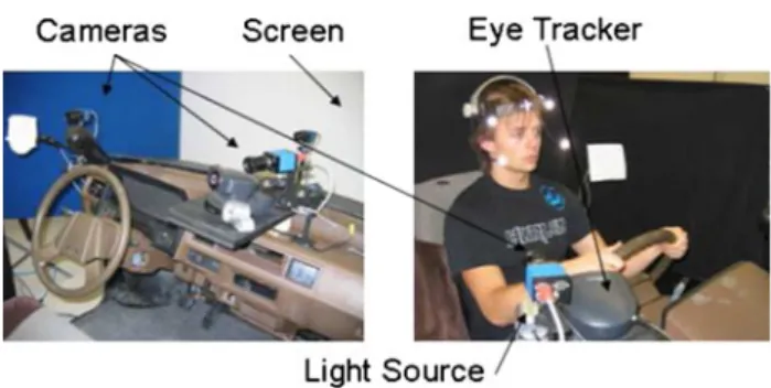
The camera setup for this project allows for several computer vision applications. Figure1 shows the sche-matics for the simulator and how the cameras are put together to provide maximum knowledge of the sur-rounding environment. The computer vision system is comprised of: (1) a set of three Black and White firewire
H. O. Hamshari (&)S. S. Beauchemin
Department of Computer Science, University of Western Ontario, 1151 Richmond Street, London, Canada e-mail: [email protected]
S. S. Beauchemin e-mail: [email protected] DOI 10.1007/s11554-010-0178-1
video cameras, (2) an infrared lighting system, (3) a virtual reality screen onto which the driving scenarios are pro-jected (Fig.2), and (4) an eye tracker camera.
Given the various tasks set out for the project, this contribution is only concerned with the detection and tracking of selected facial features in the given video sequences from the three camera inputs. We aim to detect and track the face and eyes of the driver during several driving scenarios, allowing for further processing of a driver’s visual search pattern behavior. Figure3shows the input from the three cameras.
2 Background
The method presented by Cristinacce and Cootes [7] address the issue of recognizing specific facial features such as the eye pupils. After acquiring the position and scale of a face using a global face detector, feature detec-tors are employed, providing ‘‘fit quality’’ surfaces. 15915 pixel areas around each landmark are extracted from the facial region in the training set on which feature detectors are trained. The simplest feature detector used in the system is a normalized correlation template which involves averaging and scaling each feature image. Orientation maps are constructed from the normalized correlation templates by employing a sobel edge filter. The Nelder–Mead simplex method [18] is used as an optimizer to compute the parameters of the shape model and, once
principle component analysis (PCA) is applied, approxi-mation of any shape in the training set is achieved. The real-time facial expression recognition system proposed by Sebe et al. [19] uses a face tracker based on the Piecewise Be´zier volume deformation tracker (PBVD) presented by Tao and Huang [20]. The PBVD tracker uses a 3D wire-frame model of the face, composed of surface patches inserted into Be´zier volumes. The model is fitted onto a face through previously selected landmark points. Different classifiers are applied in order to classify the expressions. These classifiers included: (a) generative Bayesian network classifiers, (b) decision tree inducers, (c) support vector machines, (d) k-nearest neighbor learning algorithm, and (e) parallel exemplar-based learning system (PEBLS). An ‘‘authentic expression database’’ was compiled for com-parison against the Cohn–Kanade facial expression data-base [12]. Classification results showed that the authentic expression database surpassed the Cohn–Kanade database and the use of the k-nearest neighbor classifier displayed the best classification behavior.
The techniques developed by Leinhart and Maydt [15] extend upon a machine-learning approach that has origi-nally been proposed by Viola and Jones [21]. The rapid object detector (ROD) they propose consists of a cascade of boosted classifiers. Boosting is a machine learning meta-algorithm used for performing supervised learning. These boosted classifiers are trained on simple Haar-like, rect-angular features chosen by a learning algorithm based on AdaBoost [9]. Viola and Jones [22] have successfully applied their object detection method to faces, while Cristinacce and Cootes [6] have used the same method to detect facial features. Leinhart and Maydt extend the work of Viola and Jones by establishing a new set of rotated Haar-like features which can also be calculated very rap-idly while reducing the false alarm rate of the detector. In the techniques proposed by Zhu and Ji [24], a trained AdaBoost face detector is employed to locate a face in a given scene. A trained AdaBoost eye detector is applied onto the resulting face region to find the eyes; a face mesh, representing the landmark points model, is resized and imposed onto the face region as a rough estimate. Refine-ment of the model by Zhu and Ji is accomplished by fast phase-based displacement estimation on the Gabor coeffi-cient vectors associated with each facial feature. To cope with varying pose scenarios, Wang et al. [23] use asym-metric rectangular features, extended by Wang et al. from the original symmetric rectangular features described by Viola and Jones to represent asymmetric gray-level fea-tures in profile facial images.
Shape modeling methods for the purpose of facial fea-ture extraction are common among computer vision sys-tems due to their robustness [17]. Active shape models [4] (ASM) and active appearance models [5] (AAM) possess a Fig. 1 The simulator setup showing the different components used
for data acquisition
Fig. 2 Virtual reality screens showing different driving contexts:left
high capacity for facial feature registration and extraction. Such efficiency is attributed to the flexibility of these methods, thus compensating for variations in the appear-ance of faces from one subject to another [10]. However, a problem displayed by both ASM and AAM techniques is the need for initial registration of the shape model close to the fitted solution. Both methods are prone to local minima otherwise [7]. Cristinacce and Cootes [8] use an appear-ance model similar to that used in AAM, but rather than approximating pixel intensities directly, the model is used to generate feature templates via the proposed constrained local model (CLM) approach. Kanaujia et al. [13] employ a shape model based on non-negative matrix factorization (NMF), as opposed to PCA traditionally used in ASM methods. NMF models larger variations of facial expres-sions and improves the alignment of the model onto cor-responding facial features. Since large head rotations make PCA and NMF difficult to use, Kanaujia et al. use multi-class discriminative multi-classifiers to detect head pose from local face descriptors that are based on scale-invariant feature transforms (SIFT) [16]. SIFT is typically used for facial feature point extraction on a given face image and works by processing a given image and extracting features that are invariant to the common problems associated with object recognition such as scaling, rotation, translation, illumination, and affine transformations.
3 Contribution
We have designed a number of strategies to create a framework that is congruent to Kearns’ founding ideas on boosting [14]. We wanted to demonstrate how Kearns’ ideas about sets of weak learners could be extended to weak trackers. While we have not achieved a full imple-mentation of all the ideas behind adaptive boosting, the paper experimentally shows it is a definite possibility.
We then devise computational strategies to satisfy the real-time constraints imposed by the requirement of tracking the eyes of drivers in a car simulator. Toward this end, we apply sets of weak trackers to the images in an interlaced manner. For instance, computationally expen-sive trackers would be used less frequently in an image sequence than those with a lesser cost. While this approach
has the potential to reduce the accuracy of these trackers, we may still use the outputs of those that are applied more frequently in order to perform auto-correction operations to the entire set of trackers. The combined outputs of our weak trackers executing at different time intervals produce a robust real-time eye tracking system.
The eye tracking system so derived represents only one instance of our framework. We speculate that identical principles and strategies may be used to perform other types of tracking, owing to the fact that one may choose any tracker one pleases. Furthermore, this contribution constitutes a framework, as there is no limit imposed on the choice of trackers a user may employ within this frame-work. In that sense, the method we present is only but one instance of this general framework.
4 Technique description
The problem of tracking objects of interest in real-time is investigated in this paper. Traditionally, detection and tracking of objects in visual media has been performed using specific techniques. These techniques vary in terms of their robustness and computational cost. This paper proposes a framework that is built upon a foundation synonymous to boosting. In the realm of learners and classifiers, Kearns [14] examined the question of whether or not a set of weak learners can in fact create a single, strong learner. We have transformed the same question to a higher level of abstraction: can the integration of a set of weak, tracking algorithms create a single, strong tracking solution? In this section, we follow with an explanation of how such integration results in a performance improvement over conventional methods used for tracking.
Our approach makes use of several techniques for pro-cessing input sequences of drivers following given sce-narios in the simulator. Such techniques have been used successfully on their own [15, 16] and as part of a more extended framework [13]. Acceptable face and facial fea-ture detections were produced at good success rates. Each technique used in our framework is treated as a module and these modules are classified into two major groups: detectors, and trackers. Detectors localize the facial regions automatically and lay abase imageto be used for tracking Fig. 3 Visual input taken from
the three cameras mounted on the simulator
by other modules. A base image is a visual capture of a particular facial region and can be used to perform a match against several other regions throughout the input sequence. Trackers use the base image set out by the detectors and employ matching algorithms to retrieve the correct position of the same facial region across following frames. Our framework uses a tracker based on SIFT [16] and a second tracker that uses a normalized correlation coefficient (NCC) method as follows:
~ Rðx;yÞ ¼ Ph1 y0¼0 Pw1 x0¼0T~ðx0;y0ÞI~ðxþx0;yþy0Þ ffiffiffiffiffiffiffiffiffiffiffiffiffiffiffiffiffiffiffiffiffiffiffiffiffiffiffiffiffiffiffiffiffiffiffiffiffiffiffiffiffiffiffiffiffiffiffiffiffiffiffiffiffiffiffiffiffiffiffiffiffiffiffiffiffiffiffiffiffiffiffiffiffiffiffiffiffiffiffiffiffiffiffiffiffiffiffiffiffiffiffiffiffiffiffiffiffiffiffiffiffiffi Ph1 y0¼0P w1 x0¼0T~ðx0;y0Þ 2Ph1 y0¼0P w1 x0¼0I~ðxþx0;yþy0Þ 2 q
whereT~ðx0;y0Þ ¼Tðx0;y0Þ T;Iðx~ þx0;yþy0Þ ¼Iðxþx0; yþy0Þ I;and whereTandIstand for the average value of pixels in the template raster and current window of the image, respectively.T(x,y) is the value of the template pixel in the location (x,y) and I(x,y) is the value of the image pixel in the location (x,y).
The ROD proposed by Viola and Jones [21] is a hybrid in that it can be classified as both a detector and tracker; it is employed to detect the face and localize the eyes, while the SIFT and NCC trackers only deal with the eye regions. Often, a tracker in our framework may lose a target due to fast movement of the driver’s head; a false positive base image may be registered at that time and the off-target tracker may eventually be tracking the wrong region as a consequence. As a detector, the ROD localizes the face and facial features automatically. As a tracker, it is used to track the eyes in between frames and to correct off-target trackers allowing for a second registration of a base image. Figure4 shows an example of how a tracker can lose its target and provide misleading information with regards to the position of the eyes. One could argue that only one registration of the base image should be used. However, given that the classifier is not perfect, and is vulnerable according to its associated false positive rate, the base image registered could be an invalid region of the face, incorrectly perceived as an eye.
Several base image registrations are therefore needed along the sequence.
The framework uses a look-up table composed of blur-red, scaled down Gaussian images. The Gaussian pyramid method [2] creates a stack of images that are successively smaller; the base image of the pyramid is defined as the original image and each image at any given level is com-posed of local averages of pixel neighborhoods of the preceding level of the pyramid. Detectors employed in our framework process the highest level of the pyramid first. In the case where an object of interest is not detected, the next level down is processed in a similar manner. The bottom-up approach used to detect faces and eyes in our framework reduces the processing time required by the detectors.
The three cameras available on the cockpit of the sim-ulator provide all views of the driver necessary to achieve continuous tracking: a tracker may lose its target if the driver was to check his/her blind spot, but given the camera setup installed onto the cockpit, a driver can be studied at all times. In order to achieve continuous tracking, the framework must detect a change in a driver’s head pose, and act upon such an event accordingly by flipping between the available views. For each frame that is pro-cessed by the ROD tracker, the framework keeps track of the number of hits and misses for the leftmLand rightmR
eyes within a detected face. Hits lower the value ofmLor
mR whereas misses increase their values accordingly. A
switch from one view to another occurs when the value of either mL or mR exceeds a certain threshold s, signifying
that one (or 2) of the eyes are being missed, leading to the conclusion that a head pose is in progress. Depending on which eye has been repeatedly missed, the appropriate view is placed as the primary view and processed until another switch is needed.
4.1 Corrective tracking
The various methods used in our framework produce good results, whether for detecting or tracking objects of interest
Fig. 4 An example sequence where a tracker loses its target, performed on an annotated sequence of a talking face, available at Dr. Tim Cootes’ website [3]. From left to right: a the eyes, the tracker’s target in this case, have been acquired and are tracked throughout several frames,bthe person’s head moved by a significant
amount and a base image was registered according to the interval set, and, c since the base image, registered by the tracker, is a false positive, tracking is now being performed on the wrong region of the face
in a given scene. The quality of the Haar-based classifier used by the rapid object detector is determined by its ability to correctly predict classifications for unseen (neg-ative) examples. The classifier must be evaluated with a set of examples that is separate from the training set of sam-ples used to build it. In many cases, some of the negative examples that should be used during the training phase of the classifier are missed and, in such a case, errors are introduced when the same negative example is seen by the classifier.
Detectors and trackers can be corrective in that errors introduced by one module in our framework are likely to be corrected by one or more of the other modules throughout the input sequence. An off-target tracker can be corrected by a hybrid detector/tracker in order to allow for a second registration of a base image of the eye and, vice versa, where a false positive detection of the eye region by the hybrid detector/tracker can be rectified by one or more trackers with a true positive base image. Trackers, in terms of their corrective nature, in our framework are classified as follows:
Long-term correcting: trackers that are long-term cor-recting display excellent tracking results and are usually associated with a high computational expense. They are not applied to every frame of an image sequence. Short-term correcting: short-term correcting trackers are less computationally expensive when compared to long-term correcting trackers, and are involved in correcting most of the errors introduced by the other modules. They are not applied to every image frame, yet more frequently than long-term correcting ones.
Real-time correcting: real-time correcting trackers are associated with the lowest computational cost in pro-cessing the frames and are usually the least robust modules when compared to their peers. They are applied to most image frames from a sequence.
Tracking modules in our framework are classified into the above three categories based on their effectiveness as trackers, and according to their computational cost. In our framework, the hybrid detector/tracker serves as a good short-term correcting tracker, while the SIFT and NCC trackers are used as long-term and real-time correcting trackers, respectively. As a general constraint toward the application of weak trackers, the framework ensures that only one such tracker is applied per frame, as explained further within this section.
The framework has been designed with growth in mind: extra trackers may need to be added to increase the accu-racy of the system as a whole. A fourth tracker has been developed to illustrate the ease of adding extra components to the framework. The fourth tracker simply searches for the lowest average intensity over am9nneighborhood of
pixels in a given region of interest; this operation, given a region close to the eyes, translates to finding the darkest areas in that region. Hence, the tracker now acts as a naive pupil finder (PPL). A possible problem could occur when the PPL tracker targets the eyebrows rather than the pupil when considering the darkest regions; both the pupils and the brows display comparable neighborhood intensities and can be mistaken for one another by the naive tracker. However, given that there are other correcting trackers employed by the framework, such problems can be easily and automatically rectified by the other trackers. It is important to note that the PPL method is less vulnerable to the off-target tracking problem discussed previously mainly due to the fact that it does not use a base image to perform the search. Thus, an off-target PPL can be set on-target by any given detector through a single true positive detection.
4.2 Real-time issues
Every real-time image processing method has an intrinsic limit: in other words, there exists a frame rate at which the process loses its real-time properties. In our case, we address real-time issues by using an interlaced application of our set of trackers. For instance, we do not apply costly corrective trackers at every frame, unlike least costly ones, as they have minimal impact on the interframe processing rate (see Sect.4.4). Hence, the maximum frame rate with which our implementation remains real-time depends on (a) the interval parameter chosen for each tracker, (b) the computational cost of the trackers, and (c) the computing capability of the hardware.
In our implementation, our choice for interval parame-ters, combined with our trackers and the hardware used, results in a real-time frame limit of 15 frames per s. 4.3 Confidence parameter
Trackers process each eye separately. Once a tracker pro-cesses a given frame within the input sequence, a dis-placement vector !v is produced, which tells the distance from the previous position of the eye to its new position at the most recent frame, and the detection window is placed accordingly. Since the accuracy of each tracker differs, a confidence parameter x is introduced to restrict weak trackers from incorrectly displacing the detection window. The SIFT tracker, for example, is more reliable than the NCC tracker and, as a result, should be given a higher confidence value than that of NCC.
Given the trackers used by our framework, four dis-placement vectors are produced: the ROD tracker vector
vR
!; the SIFT tracker vector v
S
vN
!; and the PPL tracker vector v
P
!: Additionally, three associated confidence parameters are set for each of the trackers:xR,xS,xN, and xP. Applying a separate
confi-dence parameter to each of the vectors produced by the trackers minimizes the errors produced by incorrect mat-ches and allows trackers with a higher confidence value to correct the perceived position of the eye through the dis-placement of the detection window. The disdis-placement of the detection window is then computed as follows: Vt ! ¼ Pn i¼0xi!vi Pn i¼0xi ð1Þ wherenis the total number of trackers employed,xiand!vi
are the associated confidence parameter and displacement vector, respectively, for tracker i, and !Vt is the final
displacement vector produced after processing frame t. Equation (1) assumes that each tracker i produces a dis-placement vector!vi based on the processing of the same
exact regionR(x,y) of the eyes at each frame. Choosing the best confidence parameter for a given tracker is determined experimentally on annotated (ground truth) image sequences. The confidence parameter values that maximize the true positive rate are then chosen.
The number and computational cost of trackers a user of the framework chooses directly impacts real-time perfor-mance. These issues are, of course, determined experimen-tally. However, simple detectors will run at frame-rate without severely impacting performance. Section4.4 illus-trates how (1) can be simplified to increase the performance of the framework.
4.4 Interval parameter
Running all trackers in our framework at every frame is computationally expensive. A more efficient solution is to only employ a single tracker at any given frame, as it helps increase the frame rate and produce smoother movement of the detection window. Aninterval parameterjis given to each tracker. The NCC tracker can be run at more frequent intervals in the framework than SIFT and, as a result, can be given a smaller interval parameter. In addition to the confidence parameter, the definition of long-term, short-term, and real-time corrective tracking are extended to include the interval parameter.
Given the three trackers used by our framework, three interval parameters are assigned:jR,jS,jN, andjP. Since
some of the components of our framework, namely the SIFT and NCC trackers, need to register a base image to employ their matching algorithms on their assigned frames, two additional interval parameters are set :jSbase andjNbase.
The overall time-line is reflected in Fig.5.
Since each frame in the sequence is only processed by one component in our framework, dictated by the interval parameters given to each tracker, (1) is simplified as follows:
Vt
!
¼xi!vi ð2Þ
The vector addition is eliminated from the computation of (1) since each frame t is only processed by a single trackeri.
4.5 Integration algorithm
The following describes, in detail, the algorithm employed by our framework:
1. Acquire new framegiven the selected view thought to contain a face, a new frame is acquired.
2. Build Gaussian pyramidonce a new frame is acquired, a Gaussian pyramid is built according to Sect.4. 3. Detect a face the face detector is applied to the entire
scene, in search of a profile face.
4. Track the eyes if the eyes have not been detected by the system yet, the eye detector is run on the regions of interest. In the case where the eyes have already been registered by the trackers, the system employs the appropriate tracker on the ROI, according to the associated intervalj.
5. Update detection windows the detection window for the left and right eyes are updated according to the displacement vector produced by the tracker employed, and adjusted using the confidence param-eterxassociated with the tracker. Figure6 illustrates the tracker selection process.
6. View switching assessment once the frame has been fully processed, results from the detectors and some of the trackers are used to assess the current, primary view, according to the thresholds set in Sect. 4. A view switch is performed if necessary.
ROD
Register base image Process
SIFT NCC
Timeline
Fig. 5 An example of a processed time-line according to the assigned interval parameters for each of the three tracking component in our framework
5 Results
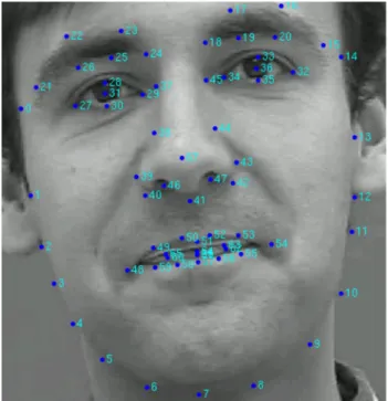
To properly identify improvements in our framework through employment of the techniques mentioned earlier, several experiments were performed on an annotated sequence of a talking face [3]. The Talking Face video is composed of 5,000 frames (200 s of video recording) taken of a person engaged in conversation. The data set of the Talking Face sequence is annotated with 68 points, as shown in Fig.7; the annotation is accurate enough to represent the movement of the facial features during the recording. Of the 68 points, the 4 points for each eye are used to report the true position of the eyes throughout the sequence. Further testing was performed on four sequences captured from the Laval University simulator labeled Jeune 04, Jeune 05, Jeune 07, and Jeune 08.
To accurately determine the true positive and false positive rates, our framework needs to compute the number
of true and false positives as well as the number of true and false negatives; this is shown in Fig. 8. The computation of true (or false) positives (or negatives) is performed at a fine pixel level to achieve accuracy. The number of true positives, for example, is calculated as the area where the detected and actual (ground truth) regions intersect, outlined in green on Fig.8. The true positive rate (or sensitivity) is computed as:
aT¼
TP
TPþFN ð3Þ
where TP and FN are the total number of true positives and false negatives found, respectively, and aT is the true
positive rate in the range [0...1]. The false positive rate (or 1 -specificity) is computed as:
aF¼
FP
FPþTN ð4Þ
where FP and TN are the total number of false positives and true negatives found, respectively, and aF is the false
positive rate in the range [0...1].
Computing the true positive and false positive rates at such a fine level provides an accurate representation to be used in plotting the receiver operating characteristic (ROC) curves for our method. However, an actual classification does not need to be described at such a fine pixel level for a true outcome to occur. Figure9 shows three detection windows. In Fig.9a, the detection window encapsulates the entire region of the eye, and is hence considered to be a hit. Figure9c is classified as a miss since the detection window deviates almost completely from the eye region, covering only a small fraction of true positives. Figure 9b, however, does cover the majority of the eye region, and therefore can be considered as a hit since it correctly classifies the region as containing an eye.
As a result, we follow to describe a coarser method for quantifying a hit rate based on whether or not the detection window contains an eye:
Run tracker Tracker 1 Tracker 2 Tracker N Update κ ω
Fig. 6 An overview of the tracker selection process employed by our framework
Fig. 7 A clipped frame taken from the Talking Face sequence showing the 68 point annotation
eye not eye eye not eye RegionActual Detected Region Image TN FN FP TP
Fig. 8 An illustration determining true positives (TP), false positives (FP), true negatives (TN), and false negatives (FN). In the image representation on therightof this figure, thesolid-line boxshows the true position of a given eye (ground truth), whereas thedashed-line boxshows the detected region of the eye
aH¼
H
HþM ð5Þ
whereH and M are the total number of hits and misses, respectively, andaHis the hit rate in the range [0...1]. The
coverage of the number of true positives as a fraction of the actual (ground truth) region of the eye from Fig.8 can be modeled as per (3). To ensure that we also model false positives into our hit–miss classification scheme, the number of true positives as a fraction of the number of false positives is accounted for as follows:
aD¼
TP
FP ð6Þ
where TP and FP are the number of true positives and false positives, respectively. The number of hitsH and misses Mcan then be computed as follows:
St¼
1 ðaTtqTÞ ^ ðaDtqDÞ
0 otherwise
ð7Þ whereaT andaD are the true positive fractions discussed
previously, at frame t, and qT and qD are thresholds by
which leniency can be given to how a hit is counted. A hit occurs whenS is 1; otherwise, a miss is counted.
Accuracy is measured by the area under the ROC curve (AUC). An AUC of 1.0 represents a perfect test; an AUC equal to 0.5 indicates a bad test since it is representative of the line of no discrimination, or random. A rough classi-fication scheme for the accuracy of our tests is as follows: • 0:90AUC1:0¼)Excellent
• 0:80AUC\0:9¼)Good • 0:70AUC\0:8¼)Average • 0:60AUC\0:7¼)Poor
• 0:50AUC\0:6¼)Unsatisfactory
Experiments were conducted on the Talking Face sequence. Different parameters were sampled in order to depict the relative trade-offs between true positives and false positives. The experiments in which different confi-dence parameters were sampled using ROD, SIFT, NCC, and PPL methods separately were performed on a segment of the Talking Face sequence rather than the entire clip, while the experiments when integrating the different methods together were performed on the entire Talking Face sequence. Furthermore, random Gaussian noise was added with varying values of r to better understand the trade-off between true positives and false positives.
5.1 Confidence parameterx
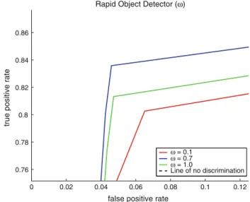
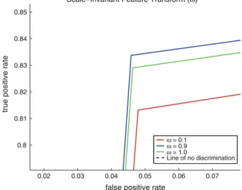
The following experiments were performed to test the performance of the separate methods when using varying values forx; the values ofxwere sampled at: 0.1, 0.3, 0.5, 0.7, 0.9, and 1.0. The NCC, SIFT, and PPL methods also employ the ROD method at a less frequent interval to lessen the vulnerability to the off-target tracking problem. The values showing the best, worst, and average levels of performance are shown on Figs.10, 11, 12 and 13. The AUC was also computed for each curve to outline the accuracy of the methods with respect to the assigned confidence parameters. The AUC values for the curves in Figs. 10,11,12and13are summarized in Table1.
(a)Perfect hit (b)Acceptable hit (c) Miss Fig. 9 An illustration showing two hits (a,b), and one miss (c), in determining whether or not the detection window covers an eye
0 0.02 0.04 0.06 0.08 0.1 0.12 0.76 0.78 0.8 0.82 0.84 0.86
false positive rate
true positive rate
Rapid Object Detector (ω)
ω = 0.1 ω = 0.7 ω = 1.0
Line of no discrimination
Fig. 10 ROC curves for the ROD method showing the three, most descriptive curves 0.03 0.04 0.05 0.06 0.07 0.08 0.78 0.79 0.8 0.81 0.82 0.83 0.84
false positive rate
true positive rate
Normalized Correlation Coefficient (ω)
ω = 0.1 ω = 0.3 ω = 1.0
Line of no discrimination
Fig. 11 ROC curves for the NCC method showing the three, most descriptive curves
5.2 Framework integration
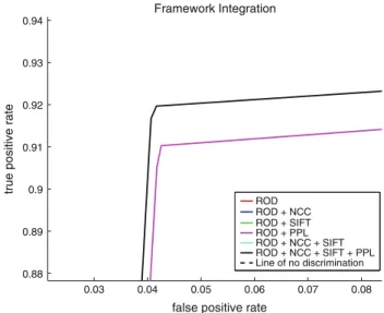
The following experiments were performed to test the ade-quacy of the methods when integrated into a single, cor-rective framework. The values showing the best, worst, and average levels of performance are shown on Figs.14and15. The AUC was also computed for each curve to outline the accuracy of the methods after integration. The AUC values for the curves in Figs.14and15are summarized in Table2.
6 Conclusion
As mentioned by Hansen and Pece [11]: ‘‘Eye tracking and detection methods fall broadly within three categories,
namely deformable templates, appearance-based, and fea-ture-based methods.’’ Given that we propose a framework which may or may not use any of those approaches, a comparison study would be inappropriate to conduct, as the problem at hand which we solve with the framework is highly specialized (car–driver eye tracking).
The ROD is run more frequently when it is employed on its own, as shown in Table3. The NCC, SIFT, and PPL methods employ the ROD method less frequently. As a result, the ROD is meant to produce slightly better results than any of the other methods due to the fact that the detector is run more frequently. Off-target tracking prob-lems help lower the performance of the NCC and SIFT methods, given that the detector is not allowed to run as often as when it is employed on its own (ROD method). 0.02 0.03 0.04 0.05 0.06 0.07 0.8 0.81 0.82 0.83 0.84 0.85
false positive rate
true positive rate
ω = 0.1 ω = 0.9 ω = 1.0
Line of no discrimination Scale−Invariant Feature Transform (ω)
Fig. 12 ROC curves for the SIFT method showing the three, most descriptive curves 0 0.02 0.04 0.06 0.08 0.1 0.12 0.8 0.82 0.84 0.86 0.88 0.9
false positive rate
true positive rate
Pupil Finder (ω)
ω = 0.5 ω = 1.0
Line of no discrimination ω = 0.1
Fig. 13 ROC curves for the PPL method showing the three, most descriptive curves
Table 1 The AUC for curves produced when the confidence parameter is varied Method x AUC ROD 0.1 0.878150 0.7 0.895555 1.0 0.883620 NCC 0.1 0.883433 0.3 0.889503 1.0 0.871861 SIFT 0.1 0.882617 0.9 0.882617 1.0 0.891356 PPL 0.1 0.891356 0.5 0.919164 1.0 0.930864 0.048 0.05 0.052 0.054 0.056 0.058 0.06 0.062 0.798 0.8 0.802 0.804 0.806 0.808 0.81 0.812
false positive rate
true positive rate
Framework Integration ROD ROD + NCC ROD + SIFT ROD + PPL ROD + NCC + SIFT ROD + NCC + SIFT + PPL Line of no discrimination
Fig. 14 ROC curves showing the performance of the methods employed by the framework, and the integration of those methods into a single, corrective framework. Only ROD, NCC, SIFT, and ROD?NCC?SIFT methods are shown on this graph
The PPL method gives the best results with a 3.5% per-formance increase over the ROD method. As explained in Sect.4.1, the PPL method is less vulnerable to off-target tracking problems, and, as a result, is shown to produce excellent results over the other methods. The SIFT method employs computationally expensive algorithms that lower the frame rate of the system. As a result, SIFT processes frames at the lowest level of the Gaussian pyramid that is employed in our framework. However, and as can be seen in our results, the performance of the SIFT tracker is also lowered, to maintain an acceptable frame rate.
The confidence parameters were chosen according to the results presented in Sect.5.1. The optimal curve with the best AUC value was chosen and the experiments were conducted accordingly. The confidence and interval parameters for each method are summarized in Tables4 and 5. As mentioned previously in this section, the NCC and SIFT methods produced lower results than the ROD method due to the fact that ROD was run more frequently when employed on its own. However, the integration of ROD, NCC and SIFT is shown to produce results close to that of the ROD method alone, as can be seen in Fig. 14. The PPL method produced the best results when compared to the ROD, NCC, and SIFT methods (all employed indi-vidually on top of the ROD method). However, the inte-gration of ROD, NCC, SIFT, and PPL method further increases the performance of the system by 0.5% over the PPL method. The full integration of the methods into a single, corrective framework then shows a performance boost of 6%. In terms of hit rate, which is a measure slightly coarser than the true positive rate (as explained in Sect.5), the ROD method, when used alone, produces a hit rate of 92.6285%. However, when integrating the entire set of methods into the framework to work together, the hit rate is increased to 99.4499%, which, according to the classification scheme for AUC is close to perfect.
With a high level of accuracy comes a high level of cost. All the experiments were performed on a laptop running a IntelPentiumM processor at 2.00 GHz. The mean frame rate when employing the ROD method alone is found to be 16.8835 frames per s. The integration of the methods Table 2 The AUC for curves produced through integration of the
various methods Method AUC ROD 0.879225 ROD?NCC 0.874807 ROD?SIFT 0.877594 ROD?PPL 0.934116 ROD?NCC?SIFT 0.878237 ROD?NCC?SIFT?PPL 0.939404
Table 3 The interval parameter values used for the various methods when they are used separately
Method jR jN jNbase jS jSbase jP
ROD (R) 2 – – – – –
NCC (N) 4 2 13 – – –
SIFT (S) 4 – – 2 11 –
PPL (P) 4 – – – – 2
Table 4 The confidence parameter values used for the various methods when they are integrated with other methods in our framework Method xR xN xS xP R 0.7 – – – R?N 0.7 0.3 – – R?S 0.7 – 0.9 – R?P 0.7 – – 1.0 R?N?S 0.7 0.3 0.9 – R?N?S?P 0.7 0.3 0.9 1.0 0.03 0.04 0.05 0.06 0.07 0.08 0.88 0.89 0.9 0.91 0.92 0.93 0.94
false positive rate
true positive rate
Framework Integration ROD ROD + NCC ROD + SIFT ROD + PPL ROD + NCC + SIFT ROD + NCC + SIFT + PPL Line of no discrimination
Fig. 15 ROC curves showing the performance of the methods employed by the framework, and the integration of those methods into a single, corrective framework. Only PPL and ROD?NCC?
SIFT?PPL methods are shown on this graph
Table 5 The interval parameter values used for the various methods when they are integrated with other methods in our framework
Method jR jN jNbase jS jSbase jP
R 2 – – – – – R?N 4 2 13 – – – R?S 4 – – 7 11 – R?P 4 – – – – 2 R?N?S 4 2 13 7 11 – R?N?S?P 4 2 13 7 11 2
lowers the frame rate to 12.3193 frames per s. The reason for the low frame rate through integration comes back to the implementation of SIFT, as it is computationally costly. A slight change in configuration of the parameters for the framework could, potentially, produce higher frame rates at excellent performance levels.
We have developed a flexible and general framework for image feature tracking which demonstrates that Kearn’s conjectures on boosting could be extended to trackers. In addition, the technique put forward for the interlaced execution of detectors constitutes a real-time solution in the context of tracking the eyes of drivers in a car simulator environment. However, when selecting a new set of trackers, priority should be given to the balance between real-time execution and accuracy. The process of auto-mating such a choice requires further research.
This research is based on the hypothesis that visual search patterns of at-risk drivers provide vital information required for assessing driving abilities and improving the skills of such drivers under varying conditions. Combined with the signals measured on the driver’s body and on the driving signals of a car simulator, the visual information allows a complete description and study of visual search pattern behavior of drivers.
References
1. Baldock, M.R.J., Mathias, J.L., McLean, A.J., Berndt, A.: Self-regulation of driving and its relationship to driving ability among older adults. Accid. Anal. Prev.38, 1038–1045 (2006)
2. Burt, P.J., Adelson, E.H.: The Laplacian pyramid as a compact image code. IEEE Trans. Commun.4, 532–540 (1983) 3. Cootes, T.F.: Images with annotations of a talking face.http://
www.isbe.man.ac.uk/*bim/data/talking_face/talking_face.html, 4 November 2007
4. Cootes, T.F., Cooper, D., Taylor, C.J., Graham, J.: Active shape models—their training and application. Comput. Vis. Image Underst.61, 38–59 (1995)
5. Cootes, T.F., Edwards, G.J., Taylor, C.J.: Active appearance models. Conf. Comput. Vis.2, 484–498 (1998)
6. Cristinacce, D., Cootes, T.: Facial feature detection using Ada-Boost with shape constraints. In: Proceedings of the British Machine Vision Conference, pp. 231–240 (2003)
7. Cristinacce, D., Cootes, T.: A comparison of shape constrained facial feature detectors. In: Proceedings of the International
Conference on Automatic Face and Gesture Recognition, pp. 375–380 (2004)
8. Cristinacce, D., Cootes, T.: Feature detection and tracking with constrained local models. In: Proceedings of the British Machine Vision Conference, pp. 929–938 (2006)
9. Freund, Y., Schapire, R.E.: A decision-theoretic generalization of on-line learning and an application to boosting. In: European Conference on Computational Learning Theory, pp. 23–37 (1995)
10. Abu Ghrabieh, R., Hamarneh, G., Gustavsson, T.: Review— active shape models—part II: image search and classification. In: Proceedings of the Swedish Symposium on Image Analysis, pp. 129–132 (1998)
11. Hansen, D.W., Pece, A.E.C.: Eye tracking in the wild. Comput. Vis. Image Underst.98(1), 155–181 (2005)
12. Kanade, T., Cohn, J.F., Yingli, T.: Comprehensive database for facial expression analysis. In: Proceedings of the International Conference on Automatic Face and Gesture Recognition, pp. 46–53 (2000)
13. Kanaujia, A., Huang, Y., Metaxas, D.: Emblem detections by tracking facial features. In: Proceedings of the IEEE Computer Vision and Pattern Recognition, pp. 108–108 (2006)
14. Kearns, M.: Thoughts on hypothesis boosting. Unpublished manuscript (1988)
15. Leinhart, R., Maydt, J.: An extended set of Haar-like features for rapid object detection. Proc. Int. Conf. Image Process.1, 900–903 (2002)
16. Lowe, D.G.: Object recognition from local scale-invariant fea-tures. Proc. Int. Conf. Comput. Vis.2, 1150 (1999)
17. Medioni, G., Kang, S.B.: Emerging Topics in Computer Vision. Prentice-Hall, Englewood Cliffs (2005)
18. Nelder, J.A., Mead, R.: A simplex method for function minimi-zation. Comput. J.7, 308–315 (1965)
19. Sebe, N., Lew, M.S., Cohen, I., Yafei, S., Gevers, T., Huang, T.S.: Authentic facial expression analysis. In: Proceedings of the International Conference on Automatic Face and Gesture Rec-ognition, pp. 242–247 (2004)
20. Tao, H., Huang, T.S.: Connected vibrations: a modal analysis approach for non-rigidmotion tracking. In: Proceedings of the Conference on IEEE Computer Vision and Pattern Recognition, pp. 735–740 (1998)
21. Viola, P., Jones, M.: Rapid object detection using a boosted cascade of simple features. Proc. IEEE Comput. Vis. Pattern Recognit.1, 511–518 (2001)
22. Viola, P., Jones, M.: Robust real-time face detection. Int J Comput. Vis.57, 137–154 (2004)
23. Wang, Y., Liu, Y., Tao, L., Xu, G.: Real-time multi-view face detection and pose estimation in video stream. In: Proceedings of the Conference on Pattern Recognition, vol. 4, pp. 354–357 (2006)
24. Zhu, Z., Ji, Q.: Robust pose invariant facial feature detection and tracking in real-time. Proc. Int. Conf. Pattern Recognit. 1, 1092–1095 (2006)