The University of Toledo
The University of Toledo Digital Repository
Theses and Dissertations2007
Secure distributed single sign-on with two-factor
authentication
Kaleb Brasee
The University of ToledoFollow this and additional works at:http://utdr.utoledo.edu/theses-dissertations
This Thesis is brought to you for free and open access by The University of Toledo Digital Repository. It has been accepted for inclusion in Theses and Dissertations by an authorized administrator of The University of Toledo Digital Repository. For more information, please see the repository'sAbout page.
Recommended Citation
A Thesis
Entitled
Secure Distributed Single Sign-On with Two-Factor Authentication
By
Kaleb Brasee
Submitted as partial fulfillment of the requirements for
The Master of Science in Engineering
Advisor: Dr. Kami Makki
College of Graduate Studies
The University of Toledo
The University of Toledo
College of Engineering
I HEREBY RECOMMEND THAT THE THESIS PREPARED UNDER
MY SUPERVISION BY
Kaleb BraseeENTITLED Secure Distributed Single Sign-On with Two-Factor Authentication
BE ACCEPTED IN PARTIAL FULFILLMENT OF THE REQUIREMENTS FOR THE DEGREE OF Master of Science in Engineering
Thesis Advisor: Dr. Kami Makki
Recommendation concurred by
Dr. Gerald Heuring
Dr. Hilda Standley
Dean, College of Engineering
Committee
On
An Abstract of
Secure Distributed Single Sign-On with Two-Factor Authentication
Kaleb Brasee
Submitted as partial fulfillment of the requirements for The Master of Science in Engineering
The University of Toledo December 2007
In this thesis we present the Secure Distributed Single Sign-On (SeDSSO) architecture. SeDSSO provides secure fault-tolerant authentication using threshold key encryption with a distributed authentication service. The authentication service consists of n total authentication servers utilizing a (t, n) threshold encryption scheme, where t distinct server-signed messages are required to generate a message signed by the service. Existing distributed SSO schemes such as CorSSO and ThresPassport are examined and the benefits of our system over these schemes are presented. SeDSSO establishes secure portable identities by defining a two-factor authentication scheme that uses both a username/password and a unique USB device. The combination of a distributed authentication service and two-factor identities allows SeDSSO to securely authenticate users in any environment.
Table of Contents
Abstract …..……….. iii Table of Contents ………. iv List of Figures ………... vi 1. Introduction ……….. 1 1.1. Motivation ………. 1 1.2. Thesis Organization ………... 2 2. Related Work ……… 4 2.1. Two-factor Authentication ……… 4 2.1.1. Overview ……… 42.1.2. Two-Factor Authentication Example ………. 6
2.1.3. Advantages and Disadvantages ……….. 7
2.2. Threshold Cryptography ……… 8
2.3. CorSSO ……….. 10
2.3.1. CorSSO Identity Setup Protocols ……….. 11
2.3.2. CorSSO Client Authentication Protocol ……… 11
2.3.3. CorSSO Client-to-Application Server Access Protocol …… 12
2.3.4. CorSSO Disadvantages ……….. 12
2.4. ThresPassport ……… 12
2.4.1. ThresPassport Identity Setup Protocols ………. 13
2.4.2. ThresPassport User Authentication Protocol ………. 14
2.4.3. ThresPassport Single Sign-On Protocol ………. 14
2.4.4. ThresPassport Disadvantages ………. 15
2.5. Distributed Certification and COCA ………. 16
3. SeDSSO Components ………. 19
3.1. Authentication Service ………. 20
3.2. Service Providers ………. 21
3.3. Users ……… 22
4. SeDSSO User Identity System ……… 24
4.1. USB Identity Device (USBID) ……… 24
4.2. Counter System ……… 26
4.3. Counter Value Operation ………. 27
5. SeDSSO Processes ……….. 29
5.1. Setup processes ……… 29
5.1.1. Session Key Generation ……… 30
5.1.3. Adding a Service Provider ……… 31
5.1.4. Adding a User ……… 32
5.2. Authentication processes ………. 34
5.2.1. User Authentication Voucher Generation ……… 35
5.2.2. Initial User Sign-on to a Service Provider ……… 37
5.2.3. Subsequent User Sign-on to a Service Provider ……… 39
5.3. Identity management processes ……… 41
5.3.1. User Account Invalidation ………. 41
6. SeDSSO Implementation and Results ………. 43
6.1. Certificate Authority Server Program ….………. 44
6.2. Authentication Server Program ……… 45
6.3. Service Provider Program ……… 47
6.4. User Program ……… 48
6.5. Implementation Tests ………... 50
6.5.1. Test Specifications ……… 50
6.5.2. Test Environment ……….. 52
6.6. Test Results ……….. 53
6.6.1. User Account Creation ………. 53
6.6.2. User Sign-on ………. 56
6.6.3. User Account Invalidation ……… 59
6.7. Security Analysis ………. 61
7. Conclusion and Future Work ……….. 64
7.1. Conclusion ……… 64
7.2. Future Work ………. 65
7.2.1. Complete Implementation ……… 65
7.2.2. Unavailable Authentication Server Detection ………. 66
List of Figures
Figure 2.1: Standard encryption compared to threshold encryption ………... 9
Figure 3.1: SeDSSO components ……….. 20
Figure 4.1: USBID architecture ………. 25
Figure 6.1: User account creation times for n = 3 and t = 2 ……….. 54
Figure 6.2: User account creation times for n = 9 and t = 5 ……….. 55
Figure 6.3: User sign-on times for n = 3 and t = 2 ……… 57
Figure 6.4: User sign-on times for n = 9 and t = 5 ……… 58
Figure 6.5: User account invalidation times for n = 3 and t = 2 ……… 59
Chapter 1
Introduction
1.1. Motivation
As the number of personal Internet-site accounts grows, organizing and remembering confidential identity information becomes more difficult for the individual. It is often impossible to use the same information on every site. Common usernames may already be taken and sites frequently impose unique requirements for passwords (e.g., the password must consist of both lowercase and uppercase letters or it must contain a digit). In an RSA Security survey, more than 30% of users reported needing between 6 to 12 different passwords for their business-related logins and almost 25% said that they needed to remember 13 or more passwords [8]. When people cannot remember all of their information and are forced to physically record it, the secrecy of their identity is jeopardized.
Single sign-on (SSO) allows users to verify their identity on a central system and gain access to many different resources that trust the central system. The act of proving an identity is known as authentication. A widely-used Internet SSO system could help people protect their identity secrets by replacing many site-specific logins with a single
SSO login. This would make it possible for the average user to choose secure identity information and remember it without writing it down. Correspondingly, this system would reduce the need for insecure transmission of logins through email when users forget their information.
Various SSO architectures have been proposed and implemented over the past decade, but none have been used significantly on large-scale public Internet domains. Microsoft Passport is one of the most well-known attempts at widespread SSO. Many web sites initially planned to trust Passport identities that belonged to their users. However, after numerous difficulties and vulnerabilities, Passport support was abandoned by every site except those belonging to Microsoft [26].
The motivation for this thesis is the design of a SSO system that offers improvements over existing SSO schemes. Because many users and sites will rely on the SSO central authentication system, it needs to offer fail-safe authentication that remains available and secure through partial hardware and software failures. A robust system must also provide a way for users to safely sign on from any location, including potentially insecure computers found in places such as Internet cafés and public libraries. Our system is called SeDSSO (Secure Distributed Single Sign-On) and it provides SSO services with a fail-safe distributed authentication system and secure two-factor authentication user identities.
1.2. Thesis Organization
This thesis consists of seven chapters. Chapter 1 introduces our motivation for designing SeDSSO. Chapter 2 presents an overview of the following related work topics:
two-factor authentication, threshold cryptography, existing distributed SSO systems, and distributed certification. Chapter 3 covers the basic components that make up a complete SeDSSO system. Chapter 4 details SeDSSO user identities, including the two-factor authentication scheme and the USB device used for securely transporting identities. Chapter 5 fully describes the processes executed by SeDSSO components. Chapter 6 discusses our SeDSSO prototype and the results of performed tests. Chapter 7 presents our conclusions and suggested future work.
Chapter 2
Related Work
This chapter begins with an overview of two-factor authentication. Next, a summary of threshold cryptography is presented. The chapter then discusses CorSSO and ThresPassport, two existing distributed SSO schemes. A distributed SSO system provides single sign-on to users and allocates the responsibility of authenticating these users to a network of individual authentication servers.
Finally, the topic of certification is presented. A certificate binds information about an entity to that entity’s public key and includes the signature of a trusted authority to vouch for the authenticity of the information contained on the certificate. An existing distributed certification authority scheme known as COCA (Cornell Online Certification Authority) is examined.
2.1. Two-Factor Authentication
2.1.1. Overview
The username and password system was introduced in the early 1960s as the need emerged to secure identities on timesharing systems [21]. Computing has changed
dramatically since that time, expanding from government and research to business and personal use. However, username/password pairs have remained the standard proof of identity ownership. This method is now the weakest link in modern computer security. The Carnegie Mellon Computer Emergency Response Team (CERT) reports that 80% of all security breaches it examines are related to passwords [1]. Identities can be stolen through technological means such as keystroke logging and phishing schemes. They can also be stolen through social engineering methods ranging from the complex (posing as an administrative authority and coercing the user) to the simple (viewing a handwritten username/password lying on a desk).
In light of these weaknesses, systems have been developed which require additional identity proof. Identity proof mechanisms are divided into general categories known as the identity factors. A two-factor authentication system requires that valid credentials from two different factors be presented before a user is trusted. Many different methods can be used to prove an identity, but most fall into one of the following factors:
1. “Something you know” – memorized information (e.g., a password or answer to a secret question).
2. “Something you have” – possession of a unique item containing secret information (e.g., a smart card, bar code, or USB-interface device).
3. “Something you are” – a physical trait that can be converted to digital information using specialized hardware (e.g., a retina or fingerprint scan or voice recording analysis).
On the Internet the username/password is a generally-assumed first factor belonging to the “something you know” category. Two-factor authentication system designers must choose a second factor and decide how to implement it. The second factor is often a physical device that stores a key, generates passwords, or responds to challenges from the authentication server.
2.1.2. Two-Factor Authentication Example
An example of an existing two-factor authentication system is RSA’s SecurID. SecurID identifies users with a two-factor authentication system consisting of a personal identification number (PIN) and numeric password that users know, and a device that users have [22]. This device (known as the token) features a processor and memory with a small numeric display, and it is configurable for individual users. It generates a six-digit code every minute and constantly displays the code. In order to login, a user must enter both their PIN and a concatenation of the numeric password with the current token. Authentication is successful if the PIN exists, the numeric password for that PIN is correct, and the six-digit token code matches the code expected by the server. Since the SecurID token codes are time-dependent, the server and the token must be initially synchronized and maintain the same time values in order for the codes to match.
SecurID is widely used and it significantly complicates identity theft. Authentication is not possible without both knowledge of the PIN/password and possession of the token. However, under the right circumstances it is possible to intercept communications within this system (as well as other systems using time or usage-dependent information such as one-time passwords) and perform a
man-in-the-middle attack to hijack the user’s authentication request [23]. Methods to recover the secret token key have also been discussed [24]. Still, the system is far more secure than one-factor authentication, with no successful attacks reported in SecurID’s 15-year lifecycle [22].
2.1.3. Advantages and Disadvantages
The most obvious advantage of two-factor authentication is the increased difficulty for a malicious party to acquire both authentication factors. Standalone keystroke-logging attacks are usually insufficient because the captured data is not enough to gain authentication, will not work for subsequent logins, or will only work for a very short time. Additionally, if a malicious user just obtains a token-generating device it is useless because the login information is not known. The difficulty of obtaining both factors is why two-factor authentication is often referred to as strong authentication.
Even though two-factor authentication makes electronic identity theft more difficult, it is not perfect. In systems using time-based passwords there is a small window of opportunity in which a real-time attack can occur [20]. In SecurID the window of opportunity is at most 60 seconds but an attack could theoretically take place in this time frame (although as RSA stated, such an attack has yet to be reported). A challenge and response two-factor system eliminates this threat because each new session requires a response to a different random challenge.
On a more basic level, the argument has been made that two-factor authentication is inadequate to protect users against identity theft and phishing and that it “doesn’t solve anything” [25]. Man-in-the-middle attacks allow a web site to pose as the service
provider’s site to the user, while actually passing communications back and forth between the user and service provider. Once the man-in-the-middle system has captured the necessary information from this real connection, it can perform any action as the user with that service provider.
Trojan attacks work by installing inconspicuous software directly on the computer that the user is operating. Once this software detects that a secure connection has been established, the Trojan software uses this connection to perform its own malicious activities in the background.
Many previous two-factor authentication schemes have been vulnerable to one or both of these attacks. Section 6.7 of this thesis discusses how our system operates in regards to these risks.
2.2. Threshold Cryptography
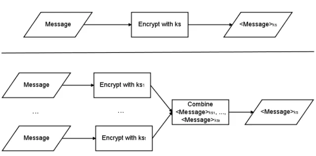
Shamir and Blakley independently proposed the threshold scheme in 1979 [4, 9]. As the title of Shamir’s paper (“How to Share a Secret”) indicates, a threshold scheme is used to safely share a secret between distinct parties so that no individual party possesses the secret. A threshold scheme divides the secret data into n data pieces and performs the division so that t data pieces, t ≤ n, are required to recreate the secret data. Each data piece is unrelated to all of the other pieces and acquiring less than t provides no information about the original data. Such a scheme is known as a (t, n) threshold scheme. In cryptography, threshold schemes can be used to divide a private key into a number of partial keys. Partial keys can be used to encrypt and decrypt a message like a full key. When a message is encrypted with t different partial keys, the resulting t
messages can be combined into one encrypted message that is identical to the message encrypted with the private key. This act of combining partially signed messages can be done without knowledge of any of the keys. If a private key is split using a (t, n) threshold scheme then n servers will possess a partial key and it will take the signature of
t servers to create a message signed with the private key. Therefore, an attacker will need
to make t successful intrusions on different authentication servers to gain control of the authentication service private key.
Figure 2.1: Encrypting a message with t partial keys and combining the partially encrypted messages produces the same output as a simple encryption with ks. However, with threshold
encryption no party is required to possess the entire private key.
When choosing the numbers t and n, n is simply the total number of servers available. This number can be changed without affecting any of the partial keys or the original key, so long as n remains greater than t. The number t cannot be modified without changing either the partial keys or the original key. Shamir suggested the formula n = 2t – 1 as a robust way for determining the total number of partial keys and
the number required to perform threshold operations [4]. When this formula is applied to a group of authentication servers, authentication is still possible even if n / 2 (or t – 1) servers are inaccessible. Similarly, an attacker can steal up to n / 2 (or t – 1) partial keys without learning the group’s private key.
Modifications to the original Shamir threshold scheme were proposed in [10]. These modifications fix a vulnerability that allows a malicious user to cheat other parties in the system and acquire the partial keys necessary to reconstruct a full key. More current schemes for threshold signatures using the RSA encryption algorithm [16] have been proposed; a popular design is Shoup’s scheme [15]. Additionally, numerous papers have been written that discuss the application of threshold cryptography in distributed system operations [13, 14].
2.3. CorSSO
Two distributed threshold SSO systems have recently been proposed. The first system to be created was CorSSO (Cornell Single Sign-on), a SSO system that provides distributed peer-to-peer network authentication [2]. This design moves authentication services that are commonly provided by application servers (or service providers) onto a set of dedicated authentication servers. A threshold scheme is used to split an authentication system’s private key into a set of partial keys, so that user authentication requires the work of several authentication servers instead of one. In addition to allowing users to create one identity and use it on all of the application servers, this system improves scalability, distributes trust, and provides fault tolerance in the authentication process.
2.3.1. CorSSO Identity Setup Protocols
CorSSO defines a client/user as a principal C that creates both a public key KC and private key kC for itself. Likewise, an application server S creates its private key kS and public key KS. S becomes accessible to principals by registering its information with a set Ni of authentication servers (known as a sub-policy set). The authentication servers in Ni create a private key ki and public key Ki for this particular set of authentication servers. Ki is sent to S for decrypting authentication system messages in the client authentication process. ki is split using threshold encryption and a unique partial key is given to each authentication server. No authentication server stores the full ki.
2.3.2. CorSSO Client Authentication Protocol
To access an application server, a client must first successfully authenticate with t authentication servers in the application server’s namespace set. The client C requests an authentication policy (a set of chosen authentication servers) from application server S and S responds by sending back a policy set P with which C must authenticate. C selects a sub-policy set Ni with which it has registered, containing only elements that are also in the set P. C requests a certificate vouching for its identity from each authentication server. If C’s identity verification is successful then each authentication server creates the same certificate and signs it with a different partial key of ki. The authentication servers send these partially signed certificates back to C. When C has received t partial certificates from the authentication servers in Ni, it uses threshold cryptography to combine them into a single certificate signed with the private key ki.
2.3.3. CorSSO Client-to-Application Server Access Protocol
When C has generated the certificate signed with ki it contacts S again and requests an authentication challenge. This challenge is a pseudo-random generated message that S encrypts with its private key kS and sends to C. C uses KS to decrypt the message, encrypts the same message with its private key kC and sends both the encrypted message and the certificate signed with ki back to S. S grants C access to its services only if it can verify that the challenge message was signed with C’s private key and that the authentication servers have vouched for C’s identity.
2.3.4. CorSSO Disadvantages
CorSSO lacks a mechanism for transferring a user’s private key so that the user can gain authentication on different computers. Copying this key without protection would allow anyone who steals the key to steal the identity of the user. CorSSO’s use of the private key to identify users is similar to identification in the Kerberos authentication system which has been noted for its mobility limitations and lack of security in untrusted environments [17].
2.4. ThresPassport
ThresPassport is a distributed SSO system that uses threshold-based key sharing to split a service provider’s secret key into a set of partial keys [3]. It was developed to address some shortcomings of the existing CorSSO system. In order for a service provider to trust a user’s identity, a set of authentication servers must be able to construct a voucher message for the user that is signed with the secret key. In contrast to CorSSO,
ThresPassport does not rely on a trusted authority to operate a public key infrastructure (PKI) for its service providers, clients, and authentication servers. ThresPassport also replaces CorSSO’s randomly generated private and public client keys with one-way hash1 keys that can be generated using only a username and password.
2.4.1. ThresPassport Identity Setup Protocols
The ThresPassport protocol begins by establishing the identity of service providers and users with a set of n authentication servers. A service provider S acquires a unique identifier number SID. It then creates a secret key KS and calculates the inverse key KS-1 such that KS-1 = (1 mod (p – 1)) / KS, where p is a randomly generated prime number. A (t, n) scheme is used to split KS into n partial keys, where signatures from t of these partial keys are required to act as the entire key KS. S then sends its unique identifier SID along with partial keys K1S through KnS to authentication servers A1 to An respectively, with each server receiving a different partial key. Each authentication server stores the partial key and SID and sends a success message to S.
Users are identified by a unique UID created by hashing their username, and a password is associated with the UID. For each authentication server, the username, password and authentication server identifier Ai are combined into strings and a one-way hash is executed on this combination to create a key (denoted KiU). This process is performed for each server to create keys K1U through KnU. U sends the UID and correct
1 A hash function, also known as a one-way hash, creates a reproducible signature or fingerprint of some
input data. The function operates in such a way that it is very unlikely to generate the same signature output from different input data. It is trivial to calculate a hash, but practically impossible to calculate the original data from the hash (hence the term one-way).
KiU to each authentication server. Upon successful storage of these values, the servers return a success response to U.
2.4.2. ThresPassport User Authentication Session Protocol
User authentication with a single authentication server is a straightforward process. The client software uses the entered username/password and the authentication server identifier to generate UID and KiU. User U then requests authentication from authentication server A. A generates a nonce nA and sends it to U. U generates its own nonce nU as well as a random number rU and encrypts the message < rU, nU, nA > with the key KiU. U sends both the UID and this encrypted message to A. If A can decrypt this message correctly using the key stored for UID and can verify that U received and decrypted the nonce nA, then A generates its own random number rA and sends the message < rA, nA, nU > encrypted with KiU to U. Now that both A and U have the numbers rA and rU, they each create a temporary session key SKU,A by hashing a combination of rA and rU. This session key is used until the session is ended manually or expires.
This process is not executed in isolation, but occurs between the user and each authentication server as a part of the single sign-on protocol described in the next section.
2.4.3. ThresPassport Single Sign-On Protocol
When a user attempts to access a service provider, the following protocol is used to verify the user’s identity and grant or deny access. The user U begins by requesting access to a service provider S. S responds with its SID, a nonce nS, and possibly a list of
authentication servers if U does not already possess such a list. U chooses t authentication servers from the optional list or from a previously-used list and establishes session key connections with each as described in the previous section. U then sends the
SID, UID, and nonce nS to each authentication server. Each server constructs the same message < UID, U, nS > and signs it with the partial key received when S registered on the authentication network. The result is t distinct messages that contain the same information but are signed with t different partial keys. The authentication servers send the messages back to U, and U uses threshold cryptography to combine them to create the message < UID, U, nS > signed with KS. U sends this message along with its UID to S. If the message encrypted with S’s public key contains the original nonce and correct UID then the user is granted access to the service.
2.4.4. ThresPassport Disadvantages
ThresPassport does not require a public key interface (PKI), and in [3] the authors claim that this is an advantage over systems that rely on a PKI. PKI algorithms require more computational power, and distributing a public and private key to each entity in the system increases the account management overhead. However, it is still arguable that the positives of a PKI outweigh these negatives. In ThresPassport, there is no way to verify that a contacted authentication server is genuine. All that is known about an authentication server is its IP address and AID, as the servers do not use cryptographic keys of any kind. Without a private key to verify the authentication server, it would be possible to execute an interception attack or DNS lookup table modification and allow
another system to pose as an authentication server without needing to possess any credentials.
ThresPassport’s username/password identity allows users to login with any computer. However, a ThresPassport identity is no safer than any other keystroke-based identity. Capturing a user’s username and password is simple, as the software to perform this capture could easily be installed on a public machine by an identity thief or on a home machine by a virus. If a ThresPassport user’s login information is captured, the malicious entity gains control of the user’s account.
The ramifications of identity theft in SSO are far worse than theft in today’s one-login-per-site system. Instead of gaining access to one area of a user’s identity the thief gains complete access, from the trivial (websites and forums) to the critical (bank accounts and credit cards). SSO needs a security framework that allows it to be easily used in multiple locations but also protects identities with something stronger than a username and password.
2.5. Certification and COCA
Certification is a method of providing trust in a PKI system. Without certification, an entity’s key is vouched for by that entity only. When an uncertified system claims to belong to a certain individual or company, there is no guarantee that this is true. Certification uses certificate authorities (or CAs), trusted third parties that everyone in the system can rely upon, to securely and correctly vouch for the identity of the entities. The CA generates a certificate during the account creation process that binds personal information (name, address, phone number, and other identifying
characteristics) with the entity’s public key, and signs a portion of the certificate with its own private key. To verify that a certificate is genuine, the CA’s public key can be used to decrypt the certificate’s signature and see that the CA signed the certificate with its private key.
The trust in certification is usually built in chains, with the set of working CAs all receiving their individual certificate from a highly-secure root CA. The root CA is never connected to any network, it is constantly protected in a restricted-access setting, and very few people can access the system. For these reasons, if a working CA server possesses a voucher certificate signed by the root CA its authenticity can be trusted more than the identity of an authentication server in a non-PKI environment.
As with authentication systems, a centralized CA can also act as a central point of failure. To solve this problem, the distributed certification system known as COCA (Cornell Online Certification Authority) has been proposed [5]. COCA uses threshold cryptography for distributed certificate operations and a Byzantine quorum system for fault-tolerance [11]. The threshold scheme employed by COCA is a (t + 1, n) scheme where n ≥ 3t + 1. With these constraints, COCA will maintain correct operations with up to t compromised certification servers. The threshold keys are periodically updated with a “proactive secret-sharing protocol”. In order to control the system, a malicious party must steal t + 1 partial keys in a relatively short amount of time. Otherwise, the keys will expire and the attack will fail.
Each COCA certification server possesses a partial key of the entire system’s private authentication key. A message must be signed by t + 1 partial keys to create a
threshold-encrypted message signed by the private key. Additionally, each server possesses an individual public and private key for communication within the certification network. These individual intranet keys can be changed frequently without the need to propagate this change to users and service providers. This operation adds security within the certification service but is also simple and efficient to perform.
Unlike the threshold protocols in CorSSO and ThresPassport where the user receives all of the partially encrypted messages and combines them, COCA users only need to contact one of the certificate servers. The contacted server forwards the user’s request to t + 1 other certificate servers. When enough partial messages have been returned the contacted server combines them into one message signed with the whole system’s private key. This approach makes it possible for COCA users to access the system without needing to possess individual server public keys, and prevents against a possible attack where a user could be sent many false partial messages and would have to determine which ones were real.
Chapter 3
SeDSSO Components
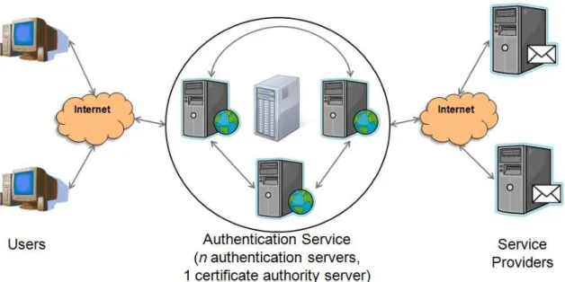
This chapter provides a detailed description of the individual components that make up the entire SeDSSO architecture. SeDSSO consists of three different components: service providers, users, and authentication servers. These components are shown in figure 3.1. Service providers are Internet sites that offer a service to users, such as email, forums, shopping, banking, etc.2 Users are individuals who access service providers to perform desired tasks. Each user possesses an account that allows service providers and authentication servers to identify them. Authentication servers store information about all users and service providers that have registered with the SeDSSO system. Multiple authentication servers form the authentication service which is responsible for authenticating SeDSSO users.
2
SeDSSO service providers are not to be confused with Internet service providers (ISPs), which are transparent to SeDSSO.
Figure 3.1: Users, Service Providers, and the Authentication Service are the three basic components of the SeDSSO system.
3.1. Authentication Service
Authentication servers are individual systems that work together to vouch for the identity of users. Because they authenticate users and store information about each SeDSSO user and service provider, these servers must be performance high-availability systems that can perform many intensive data storage, computation, and network I/O tasks simultaneously. Collectively, the group of authentication servers is referred to as the authentication service.
SeDSSO implements threshold encryption by deploying n authentication servers and generating one public and private key for the entire authentication service. This key generation takes place on the certificate authority (CA) server. The authentication service key generation is its only task, it is never connected to a network, and it is physically guarded. These steps are required to ensure the security of the authentication service’s public and private keys and thereby maximize trust in the service. The CA
server splits the private key into n partial keys with a (t, n) threshold scheme, and one partial key is given to each authentication server. Since no authentication server possesses the entire private key, at least t servers must sign an identical message in order to act as the authentication service. Every user and service provider in the SeDSSO system is given access to the authentication service public key, making it possible to verify messages signed by the authentication service private key.
Individual authentication servers each possess a self-generated public and private key to use for server-to-server communications, similar to the intranet keys found in COCA. It is only necessary that authentication servers know these keys, and they do not need to be distributed to users and service providers. The presence of these keys facilitates secure communication within the authentication service.
3.2. Service Providers
Service providers offer some type of service to users through the provider’s web site. The service provider can be a business web site or a personally-owned site and can offer any combination of free or payment-based services. The only requirement is that the service provider has the need to identify individual users. Joining SeDSSO allows this provider to offer personalized services to users without having to invest in standalone authentication software and hardware, because the authentication service performs this function for all service providers.
When a service provider account is created, it is given a unique service provider ID generated by the authentication service. The service provider creates its own public and private key pair and sends the public key to the authentication service. Each
authentication server associates the public key with the service provider ID. Once the service provider has been added, it can start accepting logins from SeDSSO users as described by the sign-on protocol.
Although the authentication service centralizes authentication for the entire SeDSSO system, its functionality does not extend into specific service provider requirements. Service providers must store all site-specific user data on their own servers, and can do this in any way they choose. As long as the stored user data is related to SeDSSO user identifiers then the service provider will be able to recall the data for that user as soon as the sign-on procedure is completed.
3.3. Users
The user account is an individual’s representation on the SeDSSO service. A user’s identity is represented by a username and password as well as a public and private key. The user creates all of these values, but the username must be verified by the authentication service to ensure that it has not been previously chosen. The username (and the corresponding username hash) is the information by which service providers, authentication servers, and other users identify an individual. It is possible for a person to separate their identity by possessing multiple accounts, although the need to remember too many usernames and passwords negates one of the major benefits that a SSO identity provides.
An email address may be entered at the time of user account creation. This address can be supplied by any email provider, even if they are not part of the SeDSSO system. When the creation process is complete, an email containing the new user’s
username and password is sent to this address. Entering an email address when creating an account is not required, but it can be done to provide an additional way to recall the account password.
A user can sign on to any service provider with his or her existing SeDSSO user identity. Upon a user’s first login, the service provider adds a new record to its own user database. Without sending any additional data to the service provider, a user should be able to perform tasks that do not require personal verification (such as browsing a store’s items or posting comments on a forum). In situations where a SeDSSO identity must be tied to a real-life identity (such as money management and store purchases) the user will need to provide additional information to the service provider. This information will be associated with the user’s account on the service provider system.
Chapter 4
SeDSSO User Identity System
SeDSSO represents users with a two-factor identity consisting of their username/password as well as information stored on a specialized USB device. The username and password is the factor that they know and the information on the USB device is the factor that they have. Possession of both factors is required for a user to successfully authenticate with the SeDSSO system. The advantage of this system is that a coordinated effort is required to steal a user’s identity, and classic one-factor attacks are insufficient. Keystroke logging software cannot access the USB device information, and the theft and examination of the USB device does not reveal the corresponding username and password.
4.1 USB Identity Device (USBID)
The SeDSSO USB identity device (USBID) is a specialized device that combines a built-in processor with flash memory and communicates with a computer through the USB interface. All of the hardware is housed in a casing the size of a normal USB flash drive. The USBID is responsible for storing the public and private keys for one or more
users, as well as the secret counter values that allow users to gain authorization with service providers. This device must be accessible by the client software every time SeDSSO account creation or authentication is requested. A similar USB-interface computation device with specialized hardware was proposed in [12], but was designed for electronic payment instead of SSO identity proof.
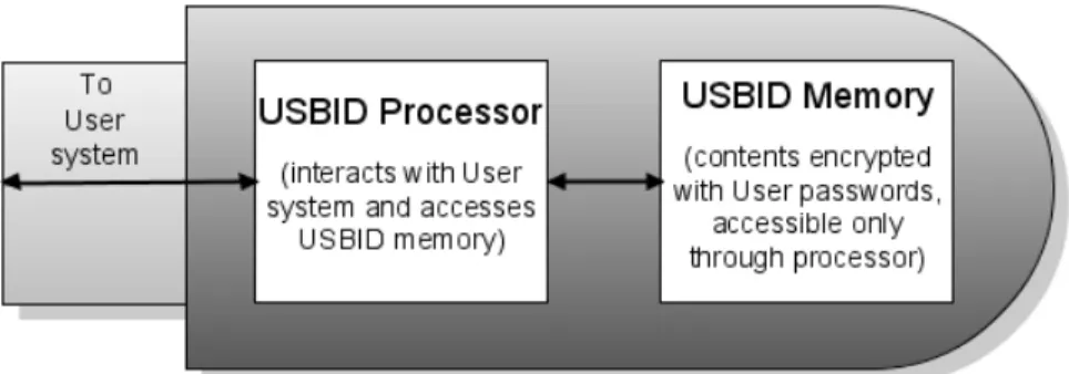
The USBID architecture is shown in figure 4.1. The processor is powered by the USB port connection. The USBID processor generates the user’s private and public key when the account is created and is responsible for performing all operations that require the use of identity factors, such as signing a message with the private key. This makes it unnecessary to pass the user’s private key to the computer where it could be observed by a program designed to retrieve this information. The public key is passed to the user’s system and sent to the authentication service for storage, but the private key remains exclusively in the USBID and is encrypted with the user’s password.
Figure 4.1: The USBID consists of botha processor and memory. The memory cannot be accessed directly by the user.
When a communication message needs to be signed during the authentication process, the client software passes the message to the USBID processor. The processor
retrieves the encrypted private key from memory and decrypts it with the password. Once the private key has been decrypted it is used to sign the message, and the signed message is returned to the client software on the user’s system.
The USBID memory is standard flash memory. However, unlike common flash drives, the USBID does not allow access to the memory through a computer file system. Only the USBID processor can access this memory. The client software translates actions in the SeDSSO client software user interface into low-level device driver commands, and these commands indicate to the USBID processor what information must be retrieved during processing. The processor acts as a black box, providing the necessary output but keeping memory retrieval, storage and modifications transparent to the user system.
4.2 Counter System
The counter system is part of the “have” factor in SeDSSO’s two-factor authentication scheme. To make authentication impossible without the USBID, a pseudo-random number generator seed is created and stored on the service provider’s system and the user’s USBID. The USBID uses the seed to generate a number during the authentication process and this number is sent to the service provider. If the service provider generates the same number then the user’s possession of the seed (and therefore possession of the USBID) has been proven.
Although the authentication service implements two-factor authentication on its own by requiring the user’s private key from the USBID, the counter system provides an effective additional layer of security. Even if t authentication servers are hacked so that a
malicious party can gain authentication as a user without the USBID, the service provider requires the counter value on the USBID independently. Possession of the correct counter value is still required to gain access to any service provider. An attacker who gains control of a user’s identity without possessing the USBID cannot access any service providers that the user has contacted in the past, because once the first authentication has been performed then a working counter is established.
4.3. Counter Value Operation
When a user attempts an authenticated connection to a service provider for the first time, the counter value between these two parties does not yet exist. In this case, the voucher for the user’s identity generated by the authentication service is sufficient for authentication. The service provider creates a seed that will be used for generating the counter, and its successful authentication response to the user includes this seed. In the future, the service provider will require that the next counter value be sent by the user in order to gain authentication.
Three variables describe the state of the counter: seed, depth, and maxDepth.
Seed is the number originally generated by the service provider and is used to seed the
pseudo-random number generator responsible for creating the counter value that is sent.
Depth is the number of times that the seeded generator is executed to produce the next
counter. When a new seed is generated depth starts at 1, and each time a connection is successful the user and service provider increment depth by 1. MaxDepth is the maximum value that depth can attain. This number changes whenever a new seed is created, and is set to the last 2 digits of the newly created seed + 1. If maxDepth did not
limit the number of times that seed is used then the authentication process would become prohibitively processor intensive as the user’s number of authentications increased.
Once depth has reached maxDepth both the user and service provider are required to independently calculate new seed, depth, and maxDepth values. The final counter value (produced by iterating maxDepth times on a seed-seeded pseudo-random number generator) is used as the new seed. Depth is reset to a value of 1, and maxDepth is set to the final 2 digits of the new seed + 1. Both parties use this process to create the next counter value and expect the other party to do the same.
Chapter 5
SeDSSO Processes
This chapter describes the operation and communication processes necessary for SeDSSO to function. The first section covers the setup processes which are responsible for initializing secure connections as well as adding new components. The authentication processes are presented next and deal with both user-to-authentication service communication as well as user-to-service provider sign-on. Finally, the processes for managing existing SeDSSO identities are discussed.
5.1. Setup Processes
The first process in this section describes the steps necessary to generate a session key and set up a secure symmetric-encryption connection. This session key is generated at the beginning of every communication process between two existing SeDSSO parties. Additionally, this section details the processes for adding new authentication servers, service providers, and users.
5.1.1. Session Key Generation
Because public/private key pairs place strict length limitations on the encrypted payload and require far more CPU effort than symmetric keys, they are only used at the beginning of a session. Once it has been verified that both communicating parties know the private key corresponding to their claimed identity, a symmetric session key is created and used for the remainder of the communication. In the following protocol, C is the connecting system and R is the receiving system.
Note that in step 1, the connecting system can send its public key as an optional parameter in situations where the receiving system does not yet have this key stored. This is necessary in some situations such as user account creation where the user account does not exist.
1. C → R: < nonceC, [KC] > KR
2. R → C: < nonceC XOR 00…0001, nonceR, SK > KC
3. C verifies that the first parameter in the above message is its generated nonce with
the last bit flipped. If so, SK is stored as the symmetric key for this session. 4. C → R: < nonceR XOR 00…0001 > SK
5. R verifies that the parameter in the above message is its generated nonce with the
last bit flipped.
5.1.2. Adding an Authentication Server
Because this process occurs very infrequently, must be highly secure and consists of extra-network steps, it is not implemented using a communication protocol. The SeDSSO simulation is provided all of the authentication server information before execution. In a real SSO system the security risk of adding a new authentication server is high enough to warrant an addition consisting of exclusively extra-network communication. When the new authentication server identity is established, it is necessary to synchronize the server’s data with the data stored by the other authentication servers.
The authentication server parameters are as follows: AID is the authentication server ID, KA is the authentication server’s individual public key, kA is the authentication server’s individual private key, IPA is the authentication server’s receiving IP address, and PA is the authentication server’s receiving port. In addition, the authentication service has a single public key KAS and a corresponding private key kAS. No server has possession of the entire service private key, but each possesses a distinct partial private key kpAS. When t distinct kpAS keys are used to create t encryptions of the same message, the encryptions can be combined to form one message encrypted with the private key kAS.
5.1.3. Adding a Service Provider
The service provider uses extra-network communication to add itself to a single authentication server Ac. Ac then uses the following protocol to add the service provider to every other authentication server.
The service provider data is referred to as follows: SID is the service provider ID,
KS is the service provider’s public key, IPS is the service provider’s receiving IP address, and PS is the service provider’s receiving port.
1. Ac establishes a secure session key connection with each authentication servers A1…An.
2. Ac→ A1…An : “ADD_SP”, 1, < SID, KS, IPS, PS > SK
3. A1…An : add this service provider to the service provider database 4. A1…An→ Ac : “ADD_SP”, 2, < “success” or “failure” > SK
5.1.4. Adding a User
User data collection and generation takes place in the initialization functions when the user software is executed. This inputs and generates all data necessary to begin the user addition process.
The user data is referred to as follows: UID is the unique user ID, UP is a hash of the username and password combined, KU/kU is the user’s public/private key combination, and INV is the account invalidation code.
The addition process begins after data collection has taken place on the user’s computer. The user enters the username and password. UID is calculated by hashing the username and UP is calculated by hashing the username and password combination. A secure pseudorandom number and computing environment data is used to seed the generator for KU, kU and INV.
1. User U establishes a secure session key connection with a random available authentication server A. U sends its newly-created public key as the optional argument.
2. U → A: “CREATE_USER”, 1, < UID, UP, KU, hash(INV) > SK
3. A verifies that the UID is not already claimed by another user account. If so, A
returns a failure and ends this process. If not, A continues.
4. A establishes a secure session key connection with all other authentication servers A1…An. Each connection uses an independent SK.
5. A → A1…An : “ADD_USER”, 1, < UID, UP, KU, hash(INV) > SK
6. A1…An decrypt and analyze the message and return one of the following messages to A.
a. If the message cannot be decrypted or data is in an improper format, send: “ADD_USER”, 2, < “general_failure” > SK.
b. If the UID has already been taken, send: “ADD_USER”, 2, < “uid_failure” > SK.
c. If the data passes validation, save the user data to a temporary variable (without yet adding the user) and send: “ADD_USER”, 2, < “success” > SK to A.
7. A receives messages from A1…An and tallies their responses.
a. If A received t or more “success” messages and no “uid_failure” messages, add the user and send: “ADD_USER”, 3, < “add” > SK to A1…An.
b. If A received less than t “success” messages or 1 or more “uid_failure” messages, send: “ADD_USER”, 3, < “discard” > SK.
8. A1…An receive the “ADD_USER”, 3 message from A and either add the user or discard the user’s information without adding.
9. A sends a message to U describing the results of the user creation process.
a. If A received t or more “success” messages and no “uid_failure” messages, send: “CREATE_USER”, 2, < “success”, UID > SK.
b. If one or more “uid_failure” messages are received the user account is not created. Send: “CREATE_USER”, 2, < “uid_failure”, UID > SK.
c. If A received less than t “success” messages after a specified time limit, send: “CREATE_USER”, 2, < “general_failure”, UID > SK.
10.U receives the message from A and reports the status to the user accordingly.
a. If U received “success”, report that the user account has been successfully created and is ready for use. The client software stores UID, KU and kU on the USBID for use in future logins. The invalidation code INV is stored on the hard drive, not the USBID, for reasons that are discussed in invalidation protocol section 5.3.1.
b. If U received “uid_failure”, report that the desired username is not available and the user should choose a new name.
c. If U received “general_failure”, report that the authentication system is not available at this time and the user should try again later.
5.2. Authentication Processes
The processes for user authentication are defined in this section. Authentication requires the user to communicate with the authentication service to obtain an identity
voucher. This voucher must contain a fresh nonce that the service provider sent to the user and must be signed with the authentication service private key. Every authentication process between a user and service provider relies on this voucher.
5.2.1. User Authentication Voucher Generation
Before a user can access a service provider, that user must receive a message signed by the authentication system that vouches for their identity. This message contains the user ID and service provider ID, the username/password hash, and a nonce created by the service provider to eliminate the possibility of replay attacks.
1. User U establishes a secure session key connection with a random available authentication server A.
2. U → A: “AUTHENTICATE_USER”, 1, < UID, UP, nonce > SK.
3. A randomly selects a set AuthSet of t-1 authentications servers which it intends to
contact. A adds both itself and these servers to a set ContactedSet.
4. A creates 2 response sets, one to collect the successful authentication responses
and the other to collect the failed authentication responses.
5. A establishes a secure session key connection with each authentication server in
the AuthSet. Each connection uses an independent SK.
6. A → ∀ Ax ∈ AuthSet: “AUTHENTICATION_CHECK”, 1, < UID, UP, nonce > SK.
a. If the UID exists and the UP corresponds to this UID, add A’s response to the success set.
b. If the UID does not exist or the UP does not correspond to this UID, add
A’s response to the failure set.
8. The servers in AuthSet decrypt and analyze the message and return one of the following messages to A.
a. If there is an error decrypting the message, the UID is not found, or the
UP for this UID is incorrect, send a failure message: “AUTHENTICATION_CHECK”, 2, < “failure” > SK.
b. If the UID exists and the UP corresponds to this ID, send a success message: “AUTHENTICATION_CHECK”, 2, < < UID, nonce > kpAS > SK. 9. A receives all responses from the AuthSet servers and adds each to the appropriate
response set.
10. If any responses are present in the failure set:
a. A randomly selects an authentication server which is not present in ContactedSet. It adds this random server to ContactedSet.
b. A sends the message from step 6 to the random server, examines the
received response, and adds the response to the success or failure set accordingly.
c. Step 10 is repeated until t successes have been counted, time runs out, or there are no more authentication servers to contact.
11. When A has received t successful responses, n total responses, or has timed out, it performs one of the two actions:
a. If t or more authentication servers responded with a successful authentication message, A threshold combines t of the partial authentication messages into one message and sends the following to U: “AUTHENTICATE_USER”, 2, < “success”, < UID, nonce > kAS > SK. b. If less than t authentication servers responded with a successful
authentication message, A sends the following to U:
“AUTHENTICATE_USER”, 2, < “failure” > SK.
5.2.2. Initial User Sign-on to a Service Provider
The sign-on procedure describes the steps necessary for a SeDSSO user with an existing account to gain access to a service provider. The following process describes a user’s first access to a service provider.
1. User U wants to access a service provider S for the first time. The client software provides an interface for U to contact S, enter the account username and password, and begin the authentication process.
2. U establishes a secure session key connection with S.
3. U → S: “USER_SIGN_ON”, 1, < UID > SK. 4. S → U: “USER_SIGN_ON”, 2, < nonceS > SK.
5. U performs the authentication message request procedure (from section 5.2.1)
using UID and nonceS.
a. If the authentication is successful, U receives the message < “success”, <
b. If the authentication is not successful, U receives the message < “failure” > SK, aborts the sign-on procedure and instructs S to do the same by sending “USER_SIGN_ON”, 3, < “failure” > SK.
6. U → S: “USER_SIGN_ON”, 3, < “success”, < UID, nonceS > kAS > SK.
7. S decrypts the message with its session key and then with the public
authentication system key KAS.
a. If the message cannot be decrypted, if UID is incorrect, if nonceS does not match the nonce originally generated by S, or if the user has signed on to S previously then the sign-on to S is denied and S sends “USER_SIGN_ON”, 4, < “failure” > SK to U.
b. If the UID correctly matches U, if nonceS is equal to the nonce generated by S in step 2, and if U has never signed on to S, then the authentication procedure continues.
8. S generates a pseudo-random long number seedUS to use as a common seed for the
counter values when U signs on to S. S stores seedUS as well as an integer depthUS (initialized to 1), which tracks the number of repetitions necessary to generate the next counter value. S also calculates the maximum depth max_depthUS by observing the two least significant of seedUS and setting max_depthUS to a number consisting of these two digits plus 1.
9. S → U: “USER_SIGN_ON”, 4, < “success”, seedUS > SK. S grants an access session to U.
10.U stores seedUS, initializes its own stored depthUS to 1, sets max_depthUS to the two least significant digits in seedUS + 1, and associates these values with S to use
for subsequent sign-on attempts. The user is now granted a session to the service provider.
5.2.3. Subsequent User Sign-on to a Service Provider
The following procedure is performed when a user attempts to sign on to a service provider that they have already successfully logged on in the past. The seedUS, depthUS and max_depthUS fields are stored by both U and S and must remain synchronized for successful authorization.
1. User U wants to access a service provider S that it has accessed before. The client software provides an interface for the user to choose S, enter their account username and password, and begin the authentication process.
2. U establishes a secure session key connection with S.
3. U → S: “USER_SIGN_ON”, 1, < UID > SK. 4. S → U: “USER_SIGN_ON”, 2, < nonceS > SK.
5. U performs the authentication message request procedure (from section 5.2.1)
using UID and nonceS.
a. If the authentication is successful, U receives the message < “success”, <
UID, nonceS > kAS > and continues the sign-on procedure.
b. If the authentication is not successful, U receives the message < “failure” > SK, aborts the sign-on procedure and instructs S to do the same by sending “USER_SIGN_ON”, 3, < “failure” > SK.
6. U generates the next counter value to send by retrieving the stored seedUS value, using it to seed a new generator, iterating through the generator depthUS times and saving that generated number as counterUS.
7. U → S: “USER_SIGN_ON”, 3, < “success”, < UID, nonceS > kAS, counterUS > SK.
8. S decrypts the message with its session key and then with the public
authentication system key KAS.
a. If the message cannot be decrypted, if UID is incorrect, if nonceS does not match the nonce originally generated by S, or if the user has never signed on to S before, then the sign-on to S is denied and S sends “USER_SIGN_ON”, 4, < “failure” > SK to U.
b. If the UID correctly matches U, if nonceS is equal to the nonce generated by S in step 2, and if U has signed on to S before, then the authentication procedure continues.
9. S uses the same process that U used in step 6 to calculate counterUS.
a. If the counter generated by S matches the counter sent by U, send “USER_SIGN_ON”, 4, < “success” > SK to U. S grants an access session to U and increments depthUS by 1.
b. If the counter generated by S does not match the counter sent by U, send “USER_SIGN_ON”, 4, < “failure” > SK to U. S does not grant access to U and does not increment depthUS.
10.U receives the message from S and decrypts the contents with the session key.
a. If the message is “success”, U increments depthUS by 1. The user is now granted a session to the service provider.
b. If the message is “failure”, the client software reports an authorization error to the user. The depthUS is not incremented.
When max_depthUS successful logins have been performed, depthUS equals
max_depthUS and both U and S must generate new seedUS, depthUS and max_depthUS values. This is done by using the last used counter value as the new seedUS, setting
depthUS back to 1, and calculating a new max_depthUS by creating a number from the last 2 digits of seedUS and adding 1. U and S perform this counter update without indicating in a message that the change is being performed.
5.3. Identity Management Processes
Identity management involves modifying an existing SeDSSO account on the authentication service. The following protocol allows a user account to be invalidated, so that any subsequent attempts to sign on are unsuccessful.
5.3.1. User Account Invalidation
The user’s system generates an invalidation number when a user account is created. The secure hash of this value is distributed to each authentication server for storage, and the actual value is stored on the user’s system (not the USBID). Access to the invalidation code is the only information necessary to invalidate the account because a thief may change the password and user information immediately after theft. In the event of a USBID theft, a computer system possessing the invalidation file can prevent the stolen account from being used.