Tool Integration at the Meta-Model Level
within the F
UJABA
Tool Suite
Sven Burmester
∗, Holger Giese
†, J¨org Niere,
Matthias Tichy
†, J¨org P. Wadsack
‡, Robert
Wagner
§, Lothar Wendehals
‡Software Engineering Group
Department of Computer Science
University of Paderborn
Warburger Straße 100
33098 Paderborn, Germany
[burmi|hg|nierej|mtt|
maroc|wagner|lowende]@upb.de
Albert Z¨undorf
Research Group Programming
Methodologies
Department of Computer Science
University of Kassel
Wilhelmsh¨oher Allee 73
34121 Kassel, Germany
[email protected]
Abstract
Current initiatives in the field of integrated development en-vironment (IDE) and CASE tool integration such as Eclipse as well as the lately happened acquisitions of Rational and Together by major IDE vendors indicate that tool integration has become an important issue for the IT industry. However, as outlined in this paper the current integration platforms fall short to address the underlying problems of overlapping data models and their consistency when it comes to a tool integra-tion. Within theFujaba Tool Suitein contrast a frame-work has been developed which enables an integration of tools at the meta-model level. We report the employed concepts for meta-model integration and consistency management in this paper and illustrate them by means of an example.
Keywords
Tool interoperability, meta-model, model integration, frame-work, graph grammars, plug-in
1.
Introduction
Nowadays tool integration gains importance in industry as well as in academia. This trend results from unifying efforts like UML and XML of the last years. Tool integration has three main problem areas.
First problem area is the integration of functionality. This means, that one tool would like to be able to use some func-tionality of another tool. This is usually easy to achieve via some Application Programming Interface (API). In addi-tion, one tool may want to modify and enhance a certain functionality of some other tool. This requires mechanisms ∗
Supported by the International Graduate School of Dyna-mic Intelligent Systems. University of Paderborn
†
This work was developed in the course of the Special Re-search Initiative 614 - Self-optimizing Concepts and Struc-tures in Mechanical Engineering - University of Paderborn, and was published on its behalf and funded by the Deutsche Forschungsgemeinschaft (DFG).
‡
This work is part of theFiniteproject funded by the DFG, project-no. SCHA 745/2-1.
§
This work has been supported by the DFG grant GA 456/7
Isileitas part of the SPP 1064.
like the template method design pattern [3] or a listener con-cept for command executions. A tighter coupling of different functionality or even a replacement of existing functionality with an alternative implementation is not always supported. Second problem area is the adaption of the (graphical) user interface of one tool by another. This includes the ex-tension of menus, tool bars and dialog windows as well as the extension of the representation of certain data at the user interface. The former points are frequently supported, the last point is seldom.
Third problem area is the access and extension of data. The data of one tool may be utilised by another tool. A tool may even try to achieve a tight integration between the data of the used platform and its own data. Generally, the problem area of integrating the data of different tools may be classified as follows: (1) the same content in different formats is integrated; (2) an integrating part contains added information; (3) the integration has to deal with overlapping information.
To integrate tools that exchange the same content in dif-ferent formats, typical solutions are standardised exchange formats (e.g. XMI) or format transformation without loss of information. A comparison about how and where the sche-mas are defined, i.e. organisation of the model data to be exchanged, is given in [9].
In case of added information a typical solution is to add extensions to the original format and hide them for the ori-ginal tool. Another solution is to use a meta-model that is extended for the integration purpose. The resulting depen-dency between the models of the different tools is that the extension depends on the involved tool or format.
To integrate tools that exchange overlapping information the multiple meta-models have to be integrated and exten-ded. To handle the data consistency during changes, an up-date mechanism has to be established. This usually requires bi-directional references between the data elements of the different tools in order to facilitate the propagation of data changes of one tool to the corresponding data elements of the other tool. Using bi-directional references easily creates mutual compile time dependencies. However, mutual com-pile time dependencies must be avoided in order to allow in-dependent tool development and to provide platforms that
shall be extensible by tools to be developed in the future. To preserve consistency when exchanging overlapping ar-tifacts is however not a new problem. The IPSEN approach [14] presented a framework to integrate tools through a com-mon meta-model. However, this approach is not easily app-licable for the integration of existing tools.
The CORUM approach [22] suggests the usage of a com-mon information model which is used by all tools. For the integration of tools, which are not based on the CORUM ap-proach and cannot use the CORUM API, the special input can be generated by means of transformation tools. In [11] the CORUM II approach is presented, integrating different reengineering tools operating on different levels. In order to exchange data all tools need to agree on a common syntac-tic format. Thus, these approaches are not applicable for the tight integration of software tools.
One prominent tool integration platform is Eclipse which is promoted by several mid-size and major IT enterprises. However the supported integration aspects are restricted to a framework which is build on a mechanism for discovering, integrating, and running plug-ins. Each plug-in uses so cal-led extension points and the Eclipse API. Further two add-ons to Eclipse, the Generative Model Transformer (GMT) and the Eclipse Modeling Framework (EMF) are provided. The GMT enables the transformation of one model to ano-ther. The EMF, beside code generation facilities out of XMI descriptions, provides a basis for interoperability of EMF-based tools. This basis is the Ecore meta-model, i.e., a cen-tral meta-model for tool integration. Further to our best knowledge, most UML tools, like TogetherJ or Rational Ro-se, are also only extendable via APIs.
In this paper we present the approach chosen within the
Fujaba Tool Suite which overcomes these problems by
means of an extensible tool integration framework.Fujaba itself is an Open Source UML CASE tool project. It was started by the software engineering group at the University of Paderborn in fall 1997 and was designed as one monolithic application integrating several functionalities from different domains. In 2002Fujabahas been redesigned and became theFujaba Tool Suitewith a plug-in architecture allowi-ng developers to add functionality easily while retainiallowi-ng full control over their contributions.
At the early days, Fujaba had a special focus on code generation from UML diagrams resulting in a visual pro-gramming language. Today, at least four rather independent tool versions are under development at the Universities of Kassel and Paderborn for supporting (1) reengineering, (2) embedded systems, (3) theFujaba Development Process, and (4) education of object-oriented concepts. According to our knowledge, quite a number of research groups have al-so chosenFujabaas a platform for their own UML related research.
The next section describes the architecture of theFujaba
Tool Suiteto support tool integration. The integration on the model level is presented in Section 3. In Section 4 the consistency management issues that result from integration on model level are sketched. Before concluding and discus-sing future work, Section 5 presents experiences with the
Fujaba Tool Suite.
2.
Architecture
TheFujaba Tool Suiteprovides a platform for the inte-gration of third party modelling tools. It offers several means to add functionality and provides infrastructure support for building menus, loading images, drawing diagrams (inclu-ding managing consistency between model and view), etc.
Plug-ins are the basic mechanism to add third party soft-ware toFujaba. A plug-in has to provide information about its version, its dependencies on other plug-ins and its devel-opers. Additionally, a plug-in can change menus and menu entries as well as pop-up menus and toolbars described in an XML based graphical user interface configuration file. Ad-ditionally, it is possible for plug-ins to notice the execution of menu actions of other plug-ins.
Fujaba’s meta-model is based on the abstract syntax graph (ASG) concept. The ASG concept provides the buil-ding blocks for the integration of theFujaba meta-model with the different meta-models provided by the third party developers. In order to support this integration Fujaba’s ASG concept implements the meta-model integration pat-tern presented in Section 3.
A basic problem for extensible frameworks is to provide the possibility to integrate meta-models although the diffe-rent meta-models might be in diffediffe-rent parts (plug-ins) of the software system.
In monolithic applications a tight integration of different meta-models is no problem, since the classes just have to be connected via bi-directional associations. In an extensible framework this solution is obviously not appropriate since the different parts would not even compile separately.
Therefore another solution must be used which preserves the separation of core and plug-in as well as allows the tight integration of the meta-models. Technically spoken, it must be possible to connect both meta-models bi-directionally wi-thout explicitly adding references to the meta-models.
These requirements demand a smart and flexible solution for bi-directional integration. The basis of the architecture is theFujabameta-model. Every tool that participates in the Fujaba Tool Suite is a plug-in. Two plug-in inter-operability variants exist. First, an existing tool (plug-in) with a meta-model should be extended by a new plug-in, i.e., the meta-model of the existing tool should be exten-ded in the new plug-in. Second, two existing tools (plug-ins) should be used in a consistent manner, i.e., instances of two meta-models should be kept consistent.
P1 P2
<<uses>> Fujaba
<<uses>>
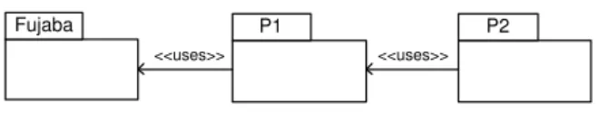
Figure 1: Architecture with meta-model extension
Figure 1 shows variant 1, the meta-model extension for an existing tool (plug-in). The plug-in P1 is an independent tool with its own meta-model. P2 is the plug-in that extends the meta-model of P1. In terms of compiling this means that P1 can be compiled alone whereas P2 cannot.
Second, two independent (existing) tools, plug-in P1 and plug-in P2, should be used together in a consistent manner. The meta-models of these two plug-ins are independent. The
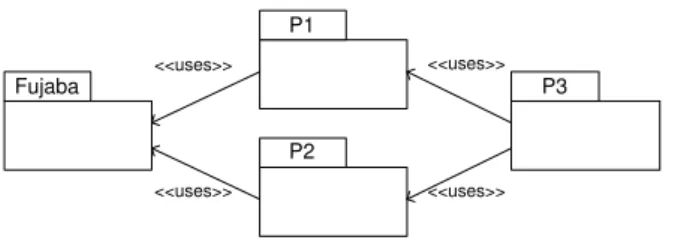
P1 P2 <<uses>> Fujaba <<uses>> P3 <<uses>> <<uses>>
Figure 2: Architecture with meta-model integration
aim is that both tools P1 and P2 can be used whereas their models are integrated. Figure 2 shows such a meta-model integration within the plug-in P3. P3 establishes the link between the two disjunct meta-models of P1 and P2. Hence, P1 and P2 are compilable separately. Of course P3 needs P1 and P2 to compile.
The next section describes the proposed meta-model in-tegration pattern and its application in theFujaba Tool
Suite to fulfill the above specified requirement on meta-model extension and integration.
3.
Integration on the Model Level
When connecting meta-models of two different tools or plug-ins, bi-directional associations are needed to naviga-te the elements of the meta-models. Figure 3 shows such a tight connection between two elements in different meta-models using an association. Each of both classes references the other class. Links between objects of those meta-model elements can then be navigated in both directions.
ConcreteElementA ConcreteElementB
0..n 0..1
< connection
Meta-Model A Meta-Model B
Figure 3: Tight connection between meta-models
Such a bi-directional association prevents a separate com-pilation of the two tools. Both meta-models depend on each other so that the tools cannot be deployed separately. For extending an existing tool where meta-model elements are distributed over different plug-ins, this approach is not suf-ficient.
Meta-Model Integration Pattern
In Figure 4 a pattern is presented to integrate different tools on the meta-model level. AMeta-Model Bcan be integrated
into Meta-Model A without affecting the interface and the
compilation ofMeta-Model A, but still a bi-directional asso-ciation between elements of the two meta-models is given.
The two classes MetaModelElementand
MetaModelAsso-ciationare provided by the tool that enables integration on
the model level. All elements of meta-models have to subty-pe the classMetaModelElement. This class provides a qua-lified association to the classMetaModelAssociation. To mo-del a bi-directional association between ConcreteElementA
ofMeta-Model AandConcreteElementBofMeta-Model Bas
depicted in Figure 3, a subclass ofMetaModelAssociationhas to be created and an association betweenConcreteElementB
andConcreteAssociationhas to be established. This
associa-tion has the same cardinalities as the intended associaassocia-tion in
MetaModelElement key MetaModelAssociation
0..1 0..1
associations >
ConcreteElementA ConcreteElementB ConcreteAssociation
0..n 0..1 connection >
Meta-Model A Meta-Model B
Figure 4: Meta-model integration pattern
Figure 3. All associations in this pattern are bi-directional. The name of theConcreteAssociationclass is used as the key for the qualifiedassociations-Association.
connection ^ Meta-Model A Meta-Model B a1:ConcreteElementA b1:ConcreteElementB assoc:ConcreteAssociation b2:ConcreteElementB connection ^ associations >
Figure 5: Objects linked via an association object
The association modelled by an additional class
Concre-teAssociationcan now be navigated in both directions.
Figu-re 5 shows how objects ofConcreteElementA and
Concrete-ElementBare linked via an association object. It is obvious
how to navigate from aConcreteElementBobjectb1via the object assocof typeConcreteAssociationto an objecta1of
type ConcreteElementA. In the other direction from a
Con-creteElementAobjecta1you can get theConcreteAssociation
object assoc by using the class name of the
ConcreteAsso-ciation as key and then navigate to an object b1 of type
ConcreteElementB.
Sample Pattern Application
The following example for meta-model integration stems from ourIsileit1project.
Isileitexplores the possibilities of
modern specification languages concerning their usefulness for the specification of flexible and autonomous producti-on cproducti-ontrol systems. The productiproducti-on cproducti-ontrol system depicted in Figure 6 consists of several working stations and robots connected by monorail tracks and switches. The switches are controlled components which allow forking and joining of the tracks. Special shuttles moving along the tracks trans-port materials and goods between the working station.
The specification of the controller software is a combina-tion of SDL block diagrams [7], UML class diagrams, and UML behaviour diagrams like collaboration diagrams, ac-tivity diagrams and state charts [17] as an executable gra-phical language. We use SDL block diagrams to specify the overall static communication structure connecting proces-ses by channels and signal routes. From this block diagram we derive an initial class diagram in which each process is represented by a respective class in the class diagram. In addition, each signal received by a process in the SDL block diagram is mapped to a method in the appropriate class in the UML class diagram. Finally, the class diagram is refi-ned and for each process class a state chart is assigrefi-ned. This briefly summarised modelling approach allows us both to
1
Isileit is the German acronym for “Integrative Specifi-cation of Distributed Production Control Systems for the Flexible Automated Manufacturing”.
Figure 6: Snapshot of a production system
specify the reactive behaviour and (with respect to the other diagrams) the modification of complex application specific object-structures. For a more detailed description of our mo-delling approach see [12, 15].
Since the UML meta-model and appropriate diagram edi-tors were already integrated in ourFujaba Tool Suite, we just had to implement an editor and the underlying meta-model for SDL block diagrams. To achieve a consistent speci-fication between the SDL block diagram (processes) and the UML class diagram (process classes), changes in the UML meta-model have to be reflected in the SDL meta-model and vice versa. Thus, a tight integration of both meta-models was required.
ASGElement key ASGAssociation
0..1 0..1 associations > UMLClass IntegrationNode SDLProcess 0..1 0..1 UML Meta-Model SDL Meta-Model ToUMLClass ToSDLProcess left > 0..1 0..1 right > Consistency Meta-Model
Figure 7: Integration of SDL and UML Meta-Models
Figure 7 shows how the meta-model integration pattern was applied twice to the UML and SDL meta-models. A connection between anSDLProcessand aUMLClassis esta-blished. Details about theIntegrationNode will be given in the next section.
4.
Inter-Model Consistency
In an integrated development environment with one ge-neral meta-model, consistency is preserved by the abstract syntax of the meta-model itself and additional well-formed-ness rules. Therefore, the consistency can be preserved wi-thin the implementation of the development environment.
This does not hold for a tool integration platform. In a tool integration platform new tools are added and old tools
are replaced by new ones. Usually, a new tool extends an exi-sting model of another tool or provides its own meta-model with overlapping data concerning other tools. This often leads to inconsistencies between the data of the inte-grated tools.
To overcome this problem, a third party tool developer has the possibility to develop the tool for one special case and to preserve the consistency in the tool itself, as seen in the previous section. The main drawback of this method is that the new tool cannot be used without the tool it relies on. For the example from Section 3 this would mean, that the SDL editor cannot be used without the UML editor. Another drawback is that a third party tool developer can-not foresee consistency rules and integrations for tools which will be developed in the future. Moreover, he cannot fore-see in which way and in which combination with other tools his tool will be used. Therefore, we need a flexible mecha-nism to specify semantic relationships between syntactically unrelated meta-models.
For this purpose, we have implemented a flexible consi-stency management plug-in. The consiconsi-stency management system allows the specification and the automated checking of consistency rules. The consistency rules and the consisten-cy checking mechanism are based on triple graph grammar theory [18]. In the original work [13], triple graph gram-mars are used for the transformation between different meta-models using an integration model (cf. Figure 8).
Meta Model B Integration Model Meta Model A Inter-Model Relation Intra-Model Relation
Figure 8: Triple Graph Grammar
Following this idea, we have adopted the triple graph grammars based on and using the integration pattern from the previous section. Assume thatMeta-Model Ais the SDL meta-model and Meta-Model B is the UML meta-model. Then we need bidirectional association from the
Integrati-on Modelto both meta-models. TheseInter-Model Relations
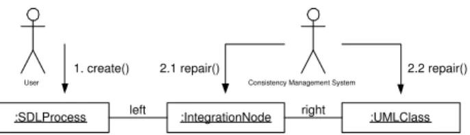
are implemented using the meta-model integration pattern. In Figure 9, an application of a consistency rule is de-picted. In our example this means, that each time the user creates a new SDL process, cf. 1. create() in Figure 9, the mechanism will check the consistency rule and will search for the appropriate UML class in the class diagram. Sin-ce no such class can be found, the automatic repair action will create a new class, the appropriate integration node and new links between the SDL process and the UML class. This is depicted in Figure 9 where the:IntegrationNode
to-:SDLProcess left :IntegrationNode right :UMLClass Consistency Management System
User
1. create() 2.1 repair() 2.2 repair()
Figure 9: TGG Consistency Rule Example
gether with theleft link and the :UMLClass with theright
link are created. This way further consistency checks can be executed, for example checking for equal names or other constraints that should hold between the SDL process and the UML class. A more detailed description about our con-sistency management system can be found in [20].
5.
Experiences
After the redesign of Fujaba, it is now possible to in-tegrate third party software through plug-ins by using the meta-model integration pattern. The redesign process com-prised reengineering and analysis of the monolithic architec-ture. The parts which build the application’s core and the ones which should be rolled out into plug-ins needed to be identified. When extracting the components all associations between the core and the new created plug-ins needed to be transformed to instances of the meta-model integration pattern.
Reengineered Plug-Ins
Pattern Definition and Recognition. Two successfully ex-tracted plug-ins are the pattern definition and pattern re-cognition plug-ins. The patterns are graphically defined as graph-rewrite-rules and related to Fujaba’s UML meta-model for automatic code generation of pattern engines. The engines are used by the pattern recognition plug-in to de-tect pattern instances in source code. The source code is parsed intoFujaba’s meta-model. Information about found instances within the ASG are stored as annotation objects linked to the ASG elements. A more detailed description of our pattern recognition approach can be found in [16].
SDL and Consistency Management. Besides the extracted pattern definition and recognition, and the already mentio-ned SDL and consistency management plug-ins a couple of new plug-ins have been developed sinceFujabaoffers this mechanism.
New developed Plug-Ins
Real-Time State charts. In order to support the design of embedded systems a real-time variant of state charts was created [2, 4]. Execution times, deadlines and time cons-traints are considered on the modelling level and induce transitions to react and fire within predictable time inter-vals. Events are generated through the call of special signal-methods wherefore an association to the class diagram is needed.
Service-Based Architectures. As part of an effort to create a process for the development of service-based architectures [19] two plug-ins have been created for deployment and com-ponent diagrams. In order to provide a seamless support it is necessary that the interfaces within the component
dia-grams are linked at the meta-model level with the classes modelling the interfaces in the class diagram. Similarly the components specified in the component diagrams must be linked to the components deployed on different nodes in the deployment diagram. We have successfully applied the pro-posed pattern to satisfy the above described requirements.
Memory Constrained Embedded Systems. In a collabora-tive research effort our proposed meta-model integration is used to support the development of memory constrained em-bedded systems. Here we have to integrate the meta-models of class diagrams and the real-time variant of state charts with the meta-models of UML 2.0 [1] component and deploy-ment diagrams for memory constrained embedded systems. We are currently realising this support using our pattern for meta-model integration.
XProM. The XProM plug-in toFujabais a student project from University Braunschweig. The XProM plug-in extends the Fujaba Tool Suite with textual project documents supporting embedded editable UML diagrams and with di-rect support for the Fujaba development Process (FUP). In addition, XProM maintains a direct relationship between diagram elements and the sections of the project handbook, describing these diagram elements. This facilitates to keep diagrams and their descriptions consistent and up-to-date. To achieve this, the XProM plug-in makes heavy use of bi-directional links between theFujabacore meta-model and the meta-model of its textual project documents.
Data Reengineering. Other plug-ins were constructed for data reengineering tasks. For data reverse engineering pur-poses a plug-in that enables access to data repositories via JDBC was added. This plug-in, which is part of the Redd-mom project, also comprises an extended entity
relation-ship (EER) editor for data model representation and ma-nipulation. Further it contains mapping rules from logical schemas (EER diagram) to conceptual schemas (UML class diagram) and Java code generation for transactional data access. Other small plug-ins in this context are an editor for schema refactoring operation definition and execution, and an editor for constructing and generating triple-graph-grammar transformations. Beside other publications, a good overview about the functionality of these plug-ins is given in [8]; the implementation is described in [21].
Web Application. Another plug-in which is part of
Redd-momis the web application plug-in. Given web page templa-tes of the application the user can model the web applica-tion. Therefore the UML and web (XML) meta-models had to be combined. Thereby, the application logic can be pro-cessed and the results can directly be added to templates. Details of this plug-in can be found in [10]
Package Diagram. A plug-in that is under development is the addition of package diagrams to Fujaba. Package diagrams are used in several other plug-ins, e.g. XProM or
Reddmom. The functionality is restricted at the moment to
nested package diagrams, i.e., a package diagram can con-tain another package diagram, a class diagram or a use case diagram. This will be extended to more than one package per diagram and visualisation of the nested structures for packages and classes.
6.
Conclusions
The described concepts of the Fujaba Tool Suite for meta-model integration and consistency management provi-de a sound basis for the integration of plug-ins as provi- demonstra-ted with the ISILEIT example. Thus, in contrast to other tool integration platforms such as Eclipse the integration between independently developed plug-ins can include the plug-in data models as well.
Our in the last section summarised experience further in-dicate that for many interesting solutions appropriate means for the tool integration at the meta-model level is advan-tageous as reuse can be improved. Without the presented concepts for integration at the meta-model level and consi-stency management in our example either a special UML or SDL plug-in had to be developed anew to realise the requi-red consistent integration.
Besides the presented concepts for meta-model integrati-on and cintegrati-onsistency management, the ASG framework of the
FujabaTool Suite further supports a generic model
(dia-gram) exchange via theGraph eXchange Language GXL [5] or XMI. Therefore, class diagrams can be exchanged, for example, with TogetherJ via a special XMI dialect. Other XML (text) formats can also be easily realised within a ge-neric transformation mechanism [6].
Acknowledgements
We thank all students, PhD students, and all people that have helped to build the currentFujaba Tool Suitewhich is available at http://www.fujaba.de.
7.
References
[1] UML 2.0 Superstructure submission V2.0. Unpublished ad/03-01-02, Jan. 2003. Alcatel, Computer Associates, Enea Business Software, Ericsson, Fujitsu,
Hewlett-Packard, I-Logix, International Business Machines, IONA, Kabira Technologies, Motorola, Oracle, Rational Software, SOFTEAM, Telelogic, Unisys, and WebGain. [2] S. Burmester. Generierung von Java Real-Time Code f¨ur
zeitbehaftete UML Modelle. Master’s thesis, University of Paderborn, Department of Computer Science, Paderborn, Germany, September.
[3] E. Gamma, R. Helm, R. Johnson, and J. Vlissides.Design Patterns, Elements of Reusable Object-Oriented Software. Addison-Wesley, 1994.
[4] H. Giese and S. Burmester. Real-Time Statechart Semantics.TechReport tr-ri-03-239, University of Paderborn, 2003.
[5] R. Holt, A. Winter, A. Sch¨urr, and S. Sim. GXL: Towards a Standard Exchange Format. InWorking Conference on Reverse Engineering, Brisbane, Australia, Nov. 2000. IEEE Computer Society Press.
[6] P. Hoven and M. Liebrecht. Entwurf und Implementierung einer Import/Export Funktionalit¨at f¨ur die
Entwicklungsumgebung Fujaba, Aug. 2002.
[7] International Telecommunication Union (ITU), Geneva.
ITU-T Recommendation Z.100: Specification and Description Language (SDL), 1994 + Addendum 1996. [8] J. Jahnke, W. Sch¨afer, J. Wadsack, and A. Z¨undorf.
Supporting Iterations in Exploratory Database Reengineering Processes. 45(2-3):99–136, Nov. 2002. (Special Issue on Software Maintenance and Reengineering). [9] D. Jin, J. Cordy, and T. Dean. Where’s the schema? A
taxonomy of patterns for software exchange. InProc. of the
10th International Workshop on Program Comprehension
(IWPC), Paris, France, June 2002.
[10] M. M. Kamneng. Entwurfsunterst¨utzung Web-basierter Schnittstellen auf Basis der UML. Master’s thesis,
University of Paderborn, Department of Computer Science, Paderborn, Germany, Apr. 2003.
[11] R. Kazman, S. Woods, and S. J. Carri`ere. Requirements for Integrating Software Architecture and Reengineering Models: CORUM II. InProc. of the Working Conference on Reverse Engineering (WCRE’98), Honolulu, Hawaii, pages 154–163, october 1998.
[12] H. K¨ohler, U. Nickel, J. Niere, and A. Z¨undorf. Integrating UML Diagrams for Production Control Systems. InProc. of the22ndInternational Conference on Software
Engineering (ICSE), Limerick, Irland, pages 241–251. ACM Press, 2000.
[13] M. Lefering. Software Document Integration Using Graph Grammar Specifications. InProceedings of the 6th International Conference on Computing and Information, Journal of Computing and Information 1, 1, 1994, pp. 1222–1243, 1994.
[14] M. Nagl, editor.The IPSEN Approach. LNCS 1170. 1996. [15] U. Nickel, J. Niere, W. Sch¨afer, and A. Z¨undorf. Combining
Statecharts and Collaboration Diagrams for the Development of Production Control Systems. InProc. of Object-Oriented Modeling of Embedded Realtime Systems workshop (OMER). Technical Report 1999-01 University of the German Armed Forces Munich, 1999.
[16] J. Niere, W. Sch¨afer, J. Wadsack, L. Wendehals, and J. Welsh. Towards Pattern-Based Design Recovery. In
Proc. of the24thInternational Conference on Software
Engineering (ICSE), Orlando, Florida, USA, pages 338–348, May 2002.
[17] Object Management Group.OMG Unified Modeling Language Specification, Version 1.4, September 2001. OMG document ad/01-09-67.
[18] A. Sch¨urr. Specification of graph translators with triple graph grammars. InProceedings of the20thInternational
Workshop on Graph-Theoretic Concepts in Computer Science, Herrsching, Germany, June 1994. Spinger Verlag. [19] M. Tichy. Durchg¨angige Unterst¨utzung f¨ur Entwurf,
Implementierung und Betrieb von Komponenten in offenen Softwarearchitekturen mittels UML. Master’s thesis, University of Paderborn, Department of Mathematics and Computer Science, Paderborn, Germany, July 2002. [20] R. Wagner. Realisierung eines diagramm¨ubergreifenden
Konsistenzmanagement-Systems f¨ur UML-Spezifikationen. Master’s thesis, University of Paderborn, Department of Mathematics and Computer Science, Paderborn, Germany, Nov. 2001.
[21] F. Wolf. Entwicklung eines Generators f¨ur eine objektorientierte Zugriffsschicht auf einer relationalen Datenbank. Master’s thesis, University of Paderborn, Department of Computer Science, Paderborn, Germany, Apr. 2001.
[22] S. Woods, L. O’Brian, T. Lin, K. Gallagher, and A. Quilici. An architecture for interoperable program understanding tools. InProc. of the6th International Workshop on
Program Comprehension (IWPC), Ischia, Italy, pages 54–63, July 1998.