Protection Design Guide for
Telecom & Networking Interfaces
Section I: Introduction & Background
The need for robust circuit protection
> 4
Semtech advantages process & technology
> 5
Threat environment
> 6
TVS diode basics
> 8
Clamping voltage
> 9
Section II: Protection Solutions
Parts & features
> 12
Gigabit Ethernet (RClamp
®2504N)
> 15
1000BASE-T (RClamp
®3304NA)
> 16
Industrial Ethernet (RClamp
®2502L)
> 17
10/100 Ethernet (TClamp
®2502N)
> 18
10/100 Ethernet (TClamp
®3302N)
> 19
Power-Over-Ethernet (RClamp
®0524S)
> 20
High speed ports (RClamp
®0542T)
> 21
GR-1089 Lightning (TClamp
®0602N)
> 22
High-density Ethernet (RClamp
®2504P)
> 23
High-density Ethernet (RClamp
®3304P)
> 24
High-surge, 5V protection array (RClamp
®0504N)
> 25
High-surge, 5V protection array (RClamp
®0554S)
> 26
10/100 Ethernet (RClamp
®0534N)
> 27
T1/E1 GR-1089 Outer building lightning (LC01-6)
> 28
ADSL, VDSL (SR70, SRDA70-4)
> 29
xDSL circuit (SR12)
> 30
xDSL (LDCAxxc-1)
> 31
RS485 (SM712)
> 32
2-line high speed and USB port (RClamp
®0582B)
> 33
Section III: Protection Applications
IEC 61000-4-x transient immunity standards
> 36
IEC 61000-4-2 ESD standard
> 36
IEC 61000-4-4 EFT immunity standard
> 37
IEC 61000-4-5 surge standard
> 37
Lightning surge immunity per telcordia GR-1089
> 40
Lightning immunity
> 40
Transient voltage protection for gigabit Ethernet PHYs
> 42
GbE system operation over temperature
> 43
Safeguard Ethernet interfaces from cable discharge threats
> 44
Power-Over-Ethernet protection
> 46
T1/E1 circuit, intra building, outer building protection
> 48
ESD Asssocation’s Recommended Safe-Handling Level for On-Chip Protection
Today’s digital communication integrated circuits (ICs) and transceivers are
faster, more efficient, consume less power, and are smaller than ever before.
Yet the advances in IC technology and enhanced chip performance has
come with a notable tradeoff: increased susceptibility to damage from ESD,
cable discharge and lightning. Not only are transistor geometry sizes scaling
at a remarkable pace, leading to more sensitive circuits, but the on-chip
protection is increasingly being sacrificed in favor of accommodating greater
performance in the chip. As this trend progresses, high performance system
level transient voltage protection will be needed more than ever before.
The Need for Robust Circuit Protection
2kV HBM Level 1kV HBM Leve l
SafeHandlingLevel
Cost of ESD design dependent on • chip area • respins • resources • circuit performance • time-to-market
The Semtech protection portfolio offers key advantages over industry standard
TVS protection devices. These performance advantages are achieved with
Semtech’s advanced process technology. This process technology enables TVS
diode arrays with sub 5 volt working voltage, low clamping voltage, and
sub-picofarad capacitance. The compact design of the Semtech process allows devices
to be housed in low-profile, space-saving packages. Lower working voltage means
that the protection device can respond more quickly, shunt transient voltage spikes
at a lower threshold, and thus provide a lower clamping voltage. As the transient
voltage sensitivity of transceivers increases, designing with low working voltage
protection devices is critical for protecting today’s systems.
Semtech Advantages
Process & Technology
Threat Environment
Telecom and Networking interfaces are vulnerable to a variety of different transient voltage threats. These threats include electrostatic discharge (ESD), cable discharge events (CDE) and lightning surge. Interfaces that are accessible to human contact, such as RJ-45 ports, are vulnerable to transient voltage threats from ESD and cable discharge transients. Additionally, Ethernet Physical Layer Chips (PHYs) within the networking infrastructure are highly vulnerable to lightning threats. When choosing and designing an appropriate protection scheme, you should consider these transients and their inherent electrical characteristics.
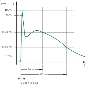
100% 90% I at 30 ns I at 60 ns 10% Ipeak tr = 0.7 to 1 ns 60 ns 30 ns I t
ESD Discharge Levels per IEC 61000-4-2
Level Air Discharge Test Voltage(kV) Test Voltage Contact Discharge (kV) First Peak Current (A) Peak Current at 30 ns (A) Peak Current at 60 ns (A) 1 2 2 7.5 4 2 2 4 4 15 8 4 3 8 6 22.5 12 6 4 15 8 30 16 8
Electrosatatic Discharge (ESD)
Several models exist to simulate the ESD event. Each is designed to describe the threat in a real world environment. The discharge model is typically a voltage source feeding a resistor/capacitor network. Resistor and capacitor values vary depending upon the standard. Today the most internationally recognized ESD standard is IEC 61000-4-2. IEC 61000-4-2 is a system level standard used by manufacturers to model ESD events from human contact. The test is performed by discharging a 150pF capacitor through a 330 ohm resistor. Discharge into the equipment may be through direct contact (contact discharge) or just prior to contact (air discharge).
IEC 61000-4-2 divides the ESD into four threat levels. Test voltages at the threat levels range from 2kV to 15kV with peak discharge currents as high as 30A. Most manufacturers adhere to the most stringent level, level 4, which defines a +/-15kV air discharge test and a +/-8kV contact discharge test. However, many manufacturers test their equipment beyond these levels. The ESD waveform as defined by IEC 61000-4-2 reaches peak magnitude in 700ps to 1ns and has a total duration of only 60ns. While the ESD pulse contains little energy, the resulting effect can be devastating to sensitive semiconductor devices. Sensitive points of the equipment are to be tested with a combination of positive and negative discharges.
IEC 61000-4-4 Current Impulse
ESD Immunity: System Level vs. Device Level
For ESD immunity, it is important to distinguish between system level immunity and device level immunity. The JEDEC JESD22-A114E which is equivalent to the earlier Mil-Std-883 is a device level standard appropriate for the level of ESD threat seen in the manufacturing environment. The IEC 61000-4-2 standard is intended to describe the level of ESD threat seen in the system environment. In the case of transceiver ICs, most are rated to 2kV human body model (HBM) according to the JEDEC Standard/Mil-Std 883. This is not the same as 2kV for the system level standard (IEC 61000-4-2). In fact, the IEC pulse, for a given voltage level, will render over 5 times higher current levels than the JEDEC standard. The chart illustrates this difference: a 2kV ESD pulse for the Mil-Std 883 renders a peak current of approximately 1.33A. For the system level, that same 2kV charge level corresponds to a peak current of 7.5A.
To achieve high system level ESD immunity, you should adhere to the IEC 61000-4-2 standard. The IEC standard is more closely representative of the real world ESD threats seen by electronic systems. Most commercial designs require passing minimum of ±8kV for the Human Body Model of IEC (level 4) contact discharge.
Cable Discharge
Cable Discharge (or CDE) is a real and frequent phenomenon in the Ethernet environment. CDE can be viewed as a type of electrostatic discharge, but should be treated as a separate transient event from ESD. An Ethernet cable, generally unshielded Cat-5 or Cat-6 twisted pair, can be modeled as a capacitor element capable of storing significant charge build up. As defined in the IEEE 802.3 standard, an Ethernet cable can be as long as 100m. The cable becomes charged by means of triboelectric charging or induction. Since Cat-5 and Cat-6 twisted pair cables exhibit very low leakage properties, the charge stored on the cable can remain on the twisted pair for up to several hours before discharging to the port during a plug event. This frequently poses a particularly dangerous threat to Ethernet ports. The high peak voltage and current of the CDE can cause the Ethernet transceiver to become overstressed resulting in intermittent malfunctions. In many cases, the transceiver can also fail catastrophically.
Lightning
Interfaces connected to the telecommunications network are exposed to lightning surges. Electromagnetic coupling of lightning energy can induce large transient pulses in nearby telecommunications lines. Lightning, or surge transients, are sometimes described as “slow” transients because unlike the fast, nanosecond rise times of ESD and Cable Discharge, a lightning pulse is generally on the order of microseconds in duration. However, the energy contained within the pulse is orders of magnitude higher, posing a significant destructive risk to telecommunications equipment.
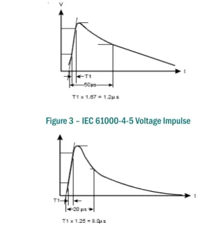
The EMC community models surge transients using a combinational waveform which describes the basic surge waveshape and character-istics: rise time duration, fall time duration, and peak pulse current (Ipp) or peak pulse voltage. The lightning waveform can be either characterized as a voltage waveform with respect to time or a current waveform with respect to time. For example, the IEC 61000-4-5 calls for a 25A 8x20µs waveform. This waveform represents a pulse of 20µs in duration from t=0 to the 50% decay point. The rise time is 8µs to the peak pulse current (Ipp), 25A in this case (see figure below).
Peak Current IEC vs JEDEC
IEC Level (Contact discharge) ESD Voltage (kV) JEDEC JESD-A114E Ipp (kV) IEC 61000-4-2 Ipp (A) 1 2 1.33 7.5 2 4 2.67 15 3 6 4.00 22.5 4 8 5.33 30TVS Diode Basics
Transient Voltage Suppression (TVS) Diodes
Transient Voltage Suppressor (TVS) diodes have long been used to provide robust circuit protection. As shown in the following diagram, TVS diodes are generally connected as shunt elements across a transmission line. Under normal operating conditions the TVS diode presents a high impedance to the protected circuit. During a transient event, the TVS achieves breakdown, presents a low impedance shunt path, and the transient current is shunted through the TVS diode. A good TVS protection circuit must divert transient current and clamp transient voltage below the failure threshold of the protected IC.
Parameters for Effective Circuit Protection
A good TVS device for protecting dataline communications interfaces must have some key parameters. First, low working voltage is a
critical TVS parameter for safeguarding submicron integrated circuits. The working voltage, or Vrwm, is the maximum rated DC voltage for the TVS device. At the Vrwm voltage, the TVS is still a non-conducting device. Once the transient voltage rises above the working voltage, the TVS quickly achieves breakdown and presents a low impedance path to divert the transient. Thus, a low working voltage is essential for clamping a transient to a level well below the damage threshold of the IC that the TVS is protecting. The I-V curve illustrates the advantage of a lower working voltage. The green line represents a typical I-V curve for a standard TVS device while the red I-V curve illustrates the Semtech’s low working voltage technology. The lower working voltage means the transient voltage is arrested more quickly and thus can be clamped to a lower voltage. Using TVS devices with lower working voltage is critical to reducing the stress energy seen by the communications transceiver. To address this need, Semtech has designed a family of 2.5V working voltage protection devices for safeguarding next generation high-speed transceivers.
Secondly, the TVS should present low capacitance to preserve signal integrity on the high-speed interface. If the capacitance of the TVS diodes is too high, adding excessive loading to the circuit, signal distortion and data errors will result.
Finally, the TVS needs to offer high-surge handling. For systems in the communications infrastructure, components rated only for ESD transient levels will not provide sufficient protection. The TVS component must also be able to handle the higher energy contained within cable discharges and the variety of lightning threats common to Ethernet interfaces. As a general guideline, the TVS should at least provide 25A of surge handling for an 8x20 microsecond pulse.
Transient Environment TVS Diode Transient Current Transient Current ESD Event Vo ltage Protected Circuit Zin I (Amps) V (Volts) Vrwm Vclamp 2.5 V Typical 5V TVS IV Curve Semtech Low Vrwm IV Curve
IV Curve for Semtech Low Working Voltage Process TVS Diode Operation
Clamping Performance for RClamp 2504N 0 5 10 15 20 25 30 0 5 10 15 20 25 30
Peak Pulse Current - Ipp (A) Clamping Voltage vs Peak Pulse Current
Clamping V olt age - Vc (V) Waveform Parameters: tr = 8µs td = 20µs Typical 5V ESD Protection Semtech RClamp 2504N
Clamping Voltage
Clamping voltage, by definition, is the maximum voltage drop across the protection device during a transient event, which is also the stress voltage seen by the protected IC. The clamping voltage is the most critical parameter to consider when choosing a TVS device. It is important to note that a device rated at IEC 61000-4-2 does not guarantee the system will pass ESD testing. This is because the IEC is a system level standard that was originally intended to be applied as pass/fail criteria for showing system level ESD immunity. The purpose of a protection device is to reduce a transient voltage spike down to a safe voltage for the protected IC, and the best way to insure that your TVS protection device adequately protects your interface circuitry is by choosing components that offer the lowest clamping voltage performance.
To illustrate the unique protection benefits of Semtech’s proprietary EPD technology, the following chart compares the clamping voltage of an industry standard 5V TVS device with the clamping voltage of the Semtech RClamp2504N device. Built on the EPD platform, the RClamp2504N offers a very low 2.5V working voltage. Notice that the Semtech RClamp2504N provides a nice low, flat clamping voltage over a wide range of peak pulse current values. As a 2.5V working voltage device, the clamping performance of the RClamp2504N is significantly lower than the typical 5V TVS protection device. As the sensitivity on next generation PHYs increases, selecting TVS devices with a lower clamping voltage as illustrated in the chart can impact the difference between safeguarding an Ethernet PHY or resulting in catastrophic damage.
High-speed copper transmission interfaces are used on a wide variety
of telecommunications systems including 3G base stations, GPON and
EPON systems, enterprise routers, switches, DSLAM equipment, digital
surveillance cameras, VoIP telephony and much more. Semtech’s industry
leading low-clamping performance and innovative packaging provide
advanced performance solutions to safeguard your systems from transient
voltage threats. This section will highlight some of the newly released key
telecom & networking devices within the Semtech protection portfolio.
Part Number
Lines
Vrwm
Cap I/O to
I/O
(8x20μs)
Ipp max
Application
Circuit Diagram
RClamp
®2504N
4
2.5V
2pF typ
25A
1000BASE-T
100BASE-T
LVDS
RClamp2504N
2.6 x 2.6 x 0.6mmRClamp
®3304NA
4
3.3V
2pF typ
25A
1000BASE-T
100BASE-T
LVDS
RClamp2504N
2.6 x 2.6 x 0.6mmRClamp
®2502L
2
2.5V
5pF max
40A
1000BASE-T
100BASE-T
Industrial
RClamp2502L
6.0 x 5.0 x 1.5mm
TClamp
®2502N
2
2.5V
8pF
95A
100BASE-T
2.6 x 2.6 x 0.6mm
TClamp
®3302N
2
3.3V
8pF
95A
100BASE-T
2.6 x 2.6 x 0.6mm
RClamp
®0524S
4
5V
1.5pF typ
6A
Power Over Ethernet
RClamp0524S 1
Part Number
Lines
Vrwm
Cap I/O to
I/O
(8x20μs)
Ipp max
Application
Circuit Diagram
RClamp
®0542T
2
5V
0.25
5A
10GBaseT
LVDS
1.6 x 1.0 x 0.4mm
TClamp
®0602N
2
6V
8pF
95A
T1/E1
T3/E3
100BASE-T
2.6 x 2.6 x 0.6mmRClamp
®2504P
4
2.5V
0.4pF
5A
1000BASE-T
100BASE-T
LVDS
Multimedia Card
1.6 x 1.6 x 0.6mmRClamp
®3304P
4
3.3V
0.4pF typ
5A
1000BASE-T
100BASE-T
LVDS
Multimedia Card
1.6 x 1.6 x 0.6mmRClamp
®0504N
4
5V
1.5pF typ
12A
1000BASE-T
100BASE-T
LVDS
2.0 x 2.0 x 0.6mm
RClamp
®0554S
4
5V
3pF
25A
10/100 Ethernet
2.90 x 2.80 x 1.10mm
RClamp
®0534N
4
5V
1.5pF
25A
10/100 Ethernet
3.0 x 2.0 x 0.60mm Note 1: surge data taken with 10/160µs waveform
Part Number
Lines
Vrwm
Cap I/O to
I/O
(8x20μs)
Ipp max
Application
Circuit Diagram
LC01-6
2
6V
50pF (max)
200A¹
T1/E1
T3/E3
LC01-6
10.20 x 10.30 x 2.5mm
SR70
2
3.3V - 70V
10pF
70A
xDSL
SR70
2.9 x 2.37 x 1.0mm
SRDA70-4
4
3.3V - 70V
4pF (typ)
20A
High-speed
xDSL lines
6.0 x 5.0 x 1.5mm
SR12
2
12V
3pF
16A
xDSL
2.9 x 2.37 x 1.0mm
LCDAxxC-1
2
12V, 24V
8pF (typ)
15A
xDSL
2.9 x 2.37 x 1.0mm
SM712
2
12V, -7V 75pF (max)
17A
RS-485
SM712 1
2.90 x 2.37 x 1.0mm
RClamp
®0582B
2
5V
1.2pF
12A
USB 2.0
Serial Interfaces
2 1
3
RClamp
®2504N
ESD & Surge Protection for 1000BASE-T
(Gigabit Ethernet) Interfaces
Features
• 2.5V working voltage • 4-line protection • Low clamping voltage • 25A (8x20μs) surge rating
• Very small package (2.6 x 2.6 x 0.6mm)
Applications
• Gigabit Ethernet • 10/100 Ethernet • LVDS
Description
The RClamp2504N uses Semtech’s enhanced Punch-Through Diode (EPD) technology process to achieve a low working voltage of 2.5 volts. The low working voltage enables superior clamping voltage performance for safeguarding submicron silicon PHY architectures. The 4-line RClamp2504N can be configured to meet the intra-building surge requirements of Telcordia GR-1089. The low clamping voltage and high surge rating of this device also make it an ideal part for protecting against dangerous ESD and cable discharge threats. The RClamp2504N presents minimal line-to-line capacitance for preserving signal integrity and is housed in a small leadless, RoHS compliant package.
RClamp2504N
Protection for Gigabit Ethernet Interface
Ethernet PHY RJ-45 TP1+ TP1-TP2+ TP2-TP3+ TP3-TP4+ TP4-RClamp2504N RClamp2504N RClamp2504N RClamp2504N 1 2 3 4 5 6 7 8
The 2.5V working voltage (Vrwm) means that the
TVS can achieve breakdown quickly during a transient event. Next generation PHYs are best protected by 2.5V working voltage TVS.
RClamp
®3304NA
ESD & Surge Protection for 1000BASE-T
(Gigabit Ethernet) Interfaces
Features
• 3.3V working voltage • 4-line protection • Low clamping voltage • 25A (8x20μs) surge rating
• Very small package (2.6 x 2.6 x 0.6mm)
Applications
• Gigabit Ethernet • 10/100 Ethernet • LVDS
Description
The RClamp3304NA uses Semtech’s advance Punch-Through technology process to achieve a low working voltage of 3.3 volts. The low working voltage enables superior clamping voltage performance for safeguarding submicron silicon PHY architectures. The 4-line RClamp3304NA can be configured to meet the intra-building surge requirements of Telcordia GR-1089, while the low clamping voltage and high surge rating of this device also make it an ideal part for protecting against dangerous ESD and cable discharge threats. The RClamp3304NA presents minimal line to line capacitance for preserving signal integrity and is housed in an ultra-small leadless, RoHS compliant package.
RClamp3304NA
Protection for Gigabit Ethernet Interface
Ethernet PHY RJ-45 TP1+ TP1-TP2+ TP2-TP3+ TP3-TP4+ TP4-RClamp3304NA RClamp3304NA RClamp3304NA RClamp3304NA 1 2 3 4 5 6 7 8
The 2.5V working voltage (Vrwm) means that the
TVS can achieve breakdown quickly during a transient event. Next generation PHYs are best protected by 2.5V working voltage TVS.
RClamp
®2502L
ESD & Surge Protection for Industrial and
Harsh Environment Ethernet Interfaces
Features
• 2.5V working voltage • 2-line protection
• 40A (8x20μs) surge rating • Low clamping voltage • Flow-through package
Applications
• 10/100 Ethernet • Gigabit Ethernet • LVDS • Analog video • Industrial interfacesDescription
The RClamp2502L is a 2-line, 2.5V (Vrwm) low capacitance protection
array for safeguarding Ethernet interfaces from ESD, cable discharge and lightning surge transients. The RClamp2502L offers a very robust surge rating for secondary lightning protection (40A, tp=8/20µs) and is housed in an industry standard SO-8 package. The SO-8 package accommodates a simple, efficient layout for the board designer, allowing the differential pair traces to run straight under the package.
Protection for Gigabit Ethernet Interface to Telcordia GR-1089
Gigabit Ethernet PHY RJ-45 RClamp2502L RClamp2502L RClamp2502L RClamp2502L 1 2 3 4 5 6 7 8 TPA+ RClamp2502L TPA-RClamp2502L Industry standard SO-8 package facilitates ease
of layout on Ethernet interfaces. The 2.5V working voltage and high-surge handling provides optimal protection in harsher industrial environments.
TClamp
®2502N
ESD & Surge Protection for
100BASE-T (10/100 Ethernet) Interfaces
Features
• 2.5V working voltage • 2-line protection • Low clamping voltage • 95A (8x20μs) surge rating
• Very small package (2.6 x 2.6 x 0.6mm)
Applications
• 10/100 Ethernet
• Video surveillance interfaces
• LVDS interfaces
Description
The TClamp2502N is a 2-line TVS protection device compliant with the Telcordia GR-1089 Intrabuilding surge standard. With it’s low capacitance (10pF), small size (2.6 x 2.6 x 0.6mm), and low operating voltage (2.5V), the TClamp2502N is the industry’s first 2.5V silicon TVS device rated to meet GR-1089 Intra-building surge. The TClamp2502N is packaged in a very small, leadless SLP package, giving designers a remarkable level of surge handling protection for a fraction of the board real estate required by traditional surge rated devices.
Protection for 10/100 Ethernet Interface
TClamp2502N TX+ TX-RX+ RX-RJ-45 Ethernet PHY TClamp2502N TClamp2502N
The 100A (2x10μs) surge rating of the TClamp2502N safeguards 10/100 PHYs from high-energy lightning threats.
TClamp
®3302N
ESD & Surge Protection for
100BASE-T (10/100 Ethernet) Interfaces
Features
• 3.3V working voltage • 2-line protection • Low clamping voltage • 95A (8x20μs) surge rating
• Very small package (2.6 x 2.6 x 0.6mm)
Applications
• 10/100 Ethernet
• Video surveillance interfaces
• LVDS interfaces
Description
The TClamp3302N is a two line TVS protection device compliant with the Telcordia GR-1089 intra building surge standard. With it’s low capacitance (<12pF), small size (2.6 x 2.6 x 0.6mm), and low operating voltage (3.3V), the TClamp3302N offers the industry’s first 3.3V silicon TVS device to meet GR-1089 Intra-building surge. The TClamp3302N is packaged into a very small, leadless SLP package.
Protection for 10/100 Ethernet Interface
TClamp3302N TX+ TX-RX+ RX-RJ-45 Ethernet PHY TClamp3302N TClamp3302N
The 100A (8x20μs) surge rating of the TClamp3302N safeguards 10/100 PHYs from high-energy lightning threats.
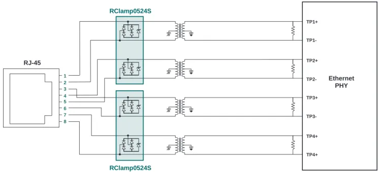
RClamp
®0524S
ESD & Cable Discharge Protection for
Power Over Ethernet Interfaces
Features
• 5V working voltage • Split-pad TVS arrays • Low clamping voltage
• Flow-through package (2.9 x 2.8 x 1.2mm)
Applications
• Power-Over-Ethernet • Industrial equipment
Description
The RClamp0524S is a 4-line, 5V (Vrwm) low capacitance protection
array designed to safeguard Power-Over-Ethernet interfaces from ESD and cable discharge transients. The split-pad architecture of the RClamp0524S protects PoE signal pairs from dangerous transient spikes while isolating the diode arrays so as to prevent a DC power connection between the pairs. The RClamp0524S offers a simple package layout to facilitate a clean, flow-through design.
Protection for Power-Over-Ethernet Interface
Ethernet PHY RJ-45 TP1+ TP1-TP2+ TP2-TP3+ TP3-TP4+ TP4+ 1 2 3 4 5 6 7 8 RClamp0524S RClamp0524S A+ A-B+ B-RClamp0524S 1 RClamp0524S
Dual isolated TVS arrays provide highly integrated transient protection solution while maintaining DC potential separation on PoE line pairs.
RClamp
®0542T
ESD & Cable Discharge Protection for High Speed Ports
Features
• Protects 2-lines operating at 5V
• Low capacitance: 0.25pF typical (I/O to I/O) • Low leakage current: < 5nA typ @ Vrwm=5V
• Innovative package allows for flow-through layout, eliminates stubs
• Small package (1.6 x 1.0 x 0.4mm)
Applications
• Protects 2-lines operating at 5V
• Low capacitance: 0.25pF typical (I/O to I/O) • Low leakage current: < 5nA typ @ Vrwm=5V
Description
The RClamp0542T is designed to protect high-speed differential pair in emerging interfaces such as 10GBASE-T and USB 3.0. The RClamp0542T is an improvement over the RClamp0522P in terms of ESD clamping performance and the leakage current is considerably lower than previous generation parts.
RClamp0542T 10G BASE-T Ethernet PHY RJ-45 Connector TP1+ TP1-TP2+ TP2-TP3+ TP3-TP4+ TP4-RClamp0542T RClamp0542T 1 2 3 4 5 6 7 8
The 2-line RClamp0542T lays out cleanly to facilitate flow-through traces on high-speed interfaces.
TClamp0602N
TClamp
®0602N
GR-1089 Lightning Protection for
T-Carrier Interfaces
Features
• 6V working voltage • Low clamping voltage • Flow-through package
• High-surge rating: 100A (2x10μs)
Applications
• T1/E1 interfaces • T3/E3 interface • Analog video interfaces • Digital surveillance cameras
Description
The TClamp0602N is a 2-line 6V working voltage device rated for 100A 2/10µs surge per Telcordia GR-1089. With its fast response time and low working voltage, the TClamp0602N will provide the initial lightning surge defense by clamping the lightning impulse to a low voltage. An enhanced diode bridge configuration is used to provide the low capacitance of the TVS diode protection circuit.
Protection for T1/E1 Interface
RTip RRing TTip TRing TClamp0602N RClamp3304N TClamp0602N T1/E1 Transciever
Line side GR-1089 Intra-building protection. The TClamp0602N is a 100A 2x10µs rated device packaged in ultra small 2.6 x 2.6 x 0.6mm package.
Ethernet PHY RJ-45 TPA+ TPA-TPB+ TPB-TPC+ TPC-TPD+ TPD-RClamp2504P RClamp2504P
RClamp
®2504P
ESD & Cable Discharge Protection for
High-Density Ethernet Interfaces
Features
• 2.5V working voltage • 4 lines of protection • Low capacitance (<0.8pF) • Excellent ESD clamping
• Ultra-small package (1.6 x 1.6 x 0.6mm)
Applications
• 1000BASE-T Ethernet • 100BASE-T Ethernet
Description
The RClamp2504P is a 4-Line, 2.5V (Vrwm) low capacitance protection
array for safeguarding Ethernet interfaces from ESD and cable discharge transients. The innovative design incorporates surge rated, low capacitance steering diodes and a TVS diode in a single package. Each line has a maximum capacitance of < 0.8pF line-to-ground. The capacitance of each line is well matched for consistant signal balance. This device is optimized for ESD protection of sensitive electronics. It may be used to meet the ESD immunity requirements of IEC 61000-4-2, Level 4 (±15kV air, ±8kV contact discharge).
Protection for High-Density Ethernet Interface
RClamp2504P
RClamp2504P Ultra-small, 4-line RClamp2504P providessuperior fast transient clamping performance with minimal part footprint.
RClamp
®3304P
ESD & Cable Discharge Protection for
High-Density Ethernet Interfaces
Features
• 3.3V working voltage • 4 lines of protection • Low capacitance (<0.8pF) • Excellent ESD clamping
• Ultra-small package (1.6 x 1.6 x 0.6mm)
Applications
• 1000BASE-T Ethernet • 100BASE-T Ethernet
Description
The RClamp3304P is a 4-Line, 3.3V (Vrwm) low capacitance protection
array designed to safeguard Ethernet interfaces from ESD and Cable Discharge transients. The monolithic design incorporates surge rated, low capacitance steering diodes and a TVS diode in a single package. Each line has a maximum capacitance of < 0.8pF to ground. The capacitance of each line is well matched for consistant signal balance. This device is optimized for ESD protection of portable electronics. It may be used to meet the ESD immunity requirements of IEC 61000-4-2, Level 4 (±15kV air, ±8kV contact discharge).
RClamp2504P
RClamp3304P Ethernet PHY RJ-45 TPA+ TPA-TPB+ TPB-TPC+ TPC-TPD+ TPD-RClamp3304P RClamp3304PESD Protection for Ethernet Interfaces Ultra-small, 4-line RClamp3304P provides superior fast transient clamping performance with minimal part footprint.
RClamp
®0504N
High-Surge, 5V Protection Array
Features
• 5V working voltage • 4-line protection
• Surge immunity: 12A (8x20µs) • Low clamping voltage
• Small SLP package
Applications
• 10/100 Ethernet • USB 2.0 • IEEE 1394Description
The RClamp0504N has a low typical capacitance of 3pF and operates with virtually no insertion loss to 1GHZ. This makes the device ideal for protection of high-speed data lines such as USB2.0, IEEE-1394, and Ethernet.
RClamp0504N TX+ TX-RX+ RX-RJ-45 Ethernet PHY
RClamp0504N
The small size of the RClamp0504Nmakes it an ideal part to use where board space is at a premium.
RClamp
®0554S
High-Surge, 5V Protection Array
Features
• 5V working voltage • 4-line protection
• Surge immunity: 25A (8x20µs) • Low clamping voltage
• Industry standard SOT-23 package
Applications
• 10/100 Ethernet • USB 2.0 • Analog video
Description
The RClamp0554S is a 5V, 4-line TVS array designed to provide robust protection from ESD, cable discharge and lightning surge. The RClamp0554S is also in a footprint compatible package with the popular SRV05-4, yet with higher surge handling to position it at the high surge end of this market.
RClamp0554S
TVS Protection for 10/100 Ethernet Interface
TX+ TX-RX+ RX-RJ-45 Ethernet PHY The RClamp0554S is pin-to-pin compatible
with the existing SRV05-4 devices, but offers a higher surge rating (25A, 8x20µs).
RClamp
®0534N
Flow-Through Surge Protection for 10/100 Ethernet
Features
• 5V working voltage • 4-line, flow-through layout
• Routing possible on one signal layer • Low clamping voltage performance • Low leakage current
Applications
• 10/100 Ethernet • USB 2.0 • IEEE-1394 • Analog video
• Industrial control lines
Description
The RClamp0534N is a 4-line 25A (8x20µs) surge rated protection array designed to address the protection needs of fast Ethernet ports. The RClamp0534N provides a very high surge immunity level in a flow-through package that allows routing all the traces on one signal layer.
RClamp0534N TX+ TX-RX+ RX-RJ-45 10/100 Ethernet PHY
The RClamp0534N’s flow-through layout enhances the flexibiilty and effectiveness of protecting 5V interfaces.
LC01-6
GR-1089 Lightning Protection for
T-Carrier Interfaces
Features
• 6V working voltage
• High-surge rating: 500A (2x10μs) • Protects one tip/ring pair • Low clamping voltage
Applications
• T1/E1 interfaces • Base stations • WAN interfaces • xDSL interfacesDescription
The LC01-6 is a 2-line 6V working voltage device rated for protecting telecom interfaces according to the GR-1089 Outerbuilding
requirements: 500A 2/10µs surge or 100A (10/1000µs) surge. The LC01-6 is commonly used to safeguard T1/E1 interfaces from very high energy lightning surge transient events. The low clamping voltage performance of the LC01-6 provides superior protection response time to transient than traditional thyristor and “crowbar” surge protectors.
Outer-building GR-1089 Protection for T1/E1 Interface
RClamp3304N T1/E1 Transceiver RTip RRing TTip TRing LC01-6 LC01-6 Tip Ring LC01-6LC01-6
Line Side GR-1089 Outer-building protection. The LC01-6 is rated for 100A 10x1000µs (500A 2x10µs) to provide maximum surge protection.
SR70
3.3V – 70V, 2-line Protection Array for
High-Speed Protection
SRDA70-4
3.3V – 70V, 4-line Protection Array for
High-Speed Protection
Features
• 12V working voltage • Low clamping voltage • 24A (8x20μs) surge rating • Flexible layout
Applications
• ADSL interfaces • VDSL interfaces • Industrial interfacesDescription
The SR70 and SRDA70-4 are surge rated diodes designed for protection of telecom interfaces. These devices are unique because they do not have a fixed voltage reference. This affords the designer the flexibility to use the protection on a wide range of interfaces. The Vcc and Gnd pins can be configured for the unique design needs by allowing a voltage clamp reference from 3.3V to 70V.
Protecting Differential Transmission Line with SRDA70-4 LINE IN LINE IN LINE IN LINE IN LINE OUT LINE OUT LINE OUT LINE OUT VCC SRDA70-4 SR70SR70 SRDA70-4
Surge rated diodes afford the flexibility of using the supply rails for clamp reference. The SR70 and SRDA70-4 can be used from 3.3V to 70V.
SR12
ESD & Surge Protection for
ADSL & VDSL Interfaces
Features
• 12V working voltage • 2-line protection array • Low clamping voltage • SOT-143 package
Applications
• ADSL interfaces • VDSL interfaces • Industrial interfacesDescription
The unique design of the SR12 incorporates four surge rated, low capacitance steering diodes and a TVS diode in a single package. During transient conditions, the steering diodes direct the transient to either the positive side of the power supply line or to ground. The internal TVS diode prevents over-voltage on the power line, protecting any downstream components.
Protecting XDSL Interface with SR12
SR12 +Vref +Vref Line Side Protection (Optional) 1 2 3 4 CODEC The SR12 can protect an ADSL or VDSL tip/
ring pair, providing very low clamping voltage and minimal capacitive load.
+12 Line Side Protection CODEC 1 2 3 4 1 2 3 4 -12 LCDA12C-1 LCDA12C-1
LCDA12C-1 and LCDA15C-1
ESD & Surge Protection for
ADSL & VDSL Interfaces
Features
• 12V & 15V working voltage • 2-line protection array • Low clamping voltage • Low leakage current • Flow-through package
Applications
• ADSL interfaces • VDSL interfaces • RS-232, RS-422Description
The LCDAxxC-1 is a low capacitance transient voltage suppressor (TVS) diode array. These devices protect sensitive CMOS ICs from dangerous ESD and secondary lightning transient threats. The LCDAxxC-1 will protect one line in common mode (line-to-ground) or one line in metallic mode (line-to-line). The low capacitance of these devices (<15pF) makes them suitable for use on high-speed telecom and datacom interfaces. The LCDAxxC-1 may be used to protect ADSL interfaces, multi-protocol serial transceivers, and wireless systems.
ADSL Protection Circuit with LCDAxxC-1
LCDA12C-1
1
2
3
4
The low clamping LCDAxxC-1 provides robust surge protection for sensitive xDSL circuitry.
SM712
ESD & Surge Protection for
RS-485 Interfaces
Features
• Protection +12V to -7V lines • Low capacitance
• Low clamping voltage • 12A (8/20μs) surge rating
Applications
• RS-485 systems • Security systems • Enterprise switching
Description
The SM712 TVS is designed for asymmetrical (+12V to -7V) protection in multi-point RS-485 systems. The SM712 will protect devices from transient voltages resulting from electrostatic discharge (ESD), electrical fast transients (EFT) and lightning surge. The device is designed with asymmetrical operating voltage for optimal protection. The TVS diodes at pins 1 and 2 have a working voltage of 12 volts. These pins are connected to the differential data line pairs. The TVS diodes at pin 3 have a working voltage of 7V. Pin 3 can be connected to ground in RS-485 applications.
Protection for RS-485 Interface with SM712
SM712 1 SM712 SM05 5V RT 12V 7V 12V 7V D R SM712
Provides bidirectional TVS protection, optimized for safeguarding RS-485 transceivers.
RClamp
®0582B
2-line High speed and USB Port Protection
Features
• Protects 1 high-speed interface • Ideal for USB data lines
• Low capacitance <1.2pF line to line • Small package size
Applications
• USB 2.0 • IEEE 1394 • Analog video
Description
The RClamp0582B is an ultra low capacitance device that is designed to protect up to two high speed data interfaces. It has a typical line-to-line capacitance of only 0.7pF, making it ideal for use on lines operating in excess of 2.5GHz. The device is housed in a small, RoHS/WEEE compliant SC-75 package.
RClamp0582B
2
1
3
Gnd
D-D+ D-D+ USB Connector USB Controller The RClamp0582B provides low clamping ESDand Surge protection up to 15A (8x20µs).
As telecommunication interfaces can be subject to wide variety of transient
conditions and operating environments, the need for good circuit protection
solutions are often unique to the application. This section will examine some of
the more subtle aspects of protecting circuit interfaces from overvoltage threats.
Circuit Protection Applications
IEC 61000-4-x Transient Immunity Standards
The International Electrotechnical Commission (IEC), a worldwide organization promoting international cooperation on questions concerning standardization in electrical & electronic fields, has developed transient immunity standards which have become minimum requirements for manufacturers wanting to do business in the European Community (EC).
Three of the IEC standards deal with transient immunity: • IEC 61000-4-2 : Electrostatic Discharge (ESD) • IEC 61000-4-4 : Electrical Fast Transient/Burst
(Electrical Fast Transients) • IEC 61000-4-5 : Surge Immunity
The following sections provide a summary of each of the transient immunity standards.
IEC 61000-4-2 – Electrical Discharge (ESD)
Standard
IEC 61000-4-2 addresses one of the most common forms of transients in electronic systems: Electrostatic discharge (ESD). ESD results from conditions which allow the build up of electrical charge from contact and separation of two non-conductive materials. When the charged body is brought in proximity of another object of lower potential, energy is released in the form of electrostatic discharge. The standard defines immunity requirements for ESD which can be coupled into the equipment directly or through radiated effects. Direct coupling includes any user accessible entry points such as I/O ports, switches, computer keyboards, panel displays, and equipment housings. Radiated coupling results from the discharge between two bodies which are external to the system.
Because the human body is one of the most common generators of ESD, the IEC standard defines a test set up which is designed to simulate an ESD event from a human body. The “Human Body Model” (HBM) as it is referred to, is considered a valid representation of worst case ESD stresses. Discharge into equipment may be through direct contact (contact discharge method) or just prior to contact (air discharge method). Contact discharge is the preferred test method, but air discharge is used where contact discharge cannot be applied.
The ESD threat is divided into four threat levels. Threat level 1 is considered the least severe while threat level 4 is the most severe. Most manufacturers will adhere to level 4: ±8kV contact discharge, ±15kV air discharge. IEC 61000-4-2 also specifies the ESD current waveform and parameters shown in Figure 1 & Table 1.
The rise time is extremely fast, defined as 0.7 to 1ns, with a second peak at 30ns and a total duration of only 60ns. The total energy contained within the pulse is approximately a few hundred microjoules. Transient Voltage Suppression (TVS) diodes are an ideal choice for meeting the ESD transient immunity requirements of IEC 61000-4-2 and are proven solutions for suppressing system level ESD events. The extremely fast response time of the TVS diode is essential for responding to the 1ns rise time of the ESD pulse. Additionally, TVS diodes are capable of clamping the incoming transient to a low enough level as not to cause damage to the protected semiconductor. All TVS diode devices and families offered by Semtech may be used to suppress ESD to level 4 of IEC 61000-4-2. The fast response and low clamping levels make TVS diodes suitable for ESD suppression on data and I/O ports.
100% 90% I at 30 ns I at 60 ns 10% Ipeak tr = 0.7 to 1 ns 60 ns 30 ns I t
Level Indicated Voltage
First peak current of discharge +/- 10% Rise time (tr) with discharge switch Current (+/- 30% at 30 ns) Current (+/- 30% at 60 ns) kV A ns A A 1 2 7.5 0.7 to 1 4 2 2 4 15 0.7 to 1 8 4 3 6 22.5 0.7 to 1 12 6 4 8 30 0.7 to 1 16 8
IEC 61000-4-4 – Electrical Fast Transients (EFT)
Immunity Standard
Electrical fast transients occur as a result of arcing contacts in switches and relays. EFT disturbances are common in industrial environments where electromechanical switches are used to connect and disconnect inductive loads. IEC 61000-4-4 specifies the EFT threat in both power and data lines. The electrical fast transient is described in terms of a voltage across a 50Ω load from a generator having a nominal dynamic source impedance of 50Ω. The output occurs as a burst of high voltage spikes at a repetition rate ranging from 2kHz to 5kHz. The burst length is defined as 15ms with bursts repeated every 300ms.
Each individual burst pulse is a double exponential waveform with a rise time of 5ns and a total duration of 50ns. A diagram showing the EFT waveform and the EFT burst repetition rate and burst period is shown in Figure 2. Four severity levels are defined in terms of an open circuit voltage as a function of installation environment.
The installation environments are defined as : 1 - Well protected
2 - Protected 3 - Typical industrial 4 - Severe industrial
Table 2 provides the open-circuit voltages for each threat level and for both power supply and data lines. Short circuit current values are estimated by dividing the EFT open-circuit voltage by its 50Ω source impedance. This represents the worse case stresses seen by the suppression element. Like ESD, EFT can be especially fatal on data and I/O lines. The fast rise time of the EFT pulses demands a suppression element with the same characteristics as that which are required for suppression of an ESD pulse. Again TVS diodes offer the best solution for suppressing the expected transient energy while keeping clamping voltages across the protected elements to a minimum.
Additionally, the extremely fast response time of TVS diodes is essential for responding to the 5ns rise time of the EFT pulse. Due to the repetitive nature of the EFT pulses, TVS diodes with slightly higher power handling capability will be required for protection at threat level 4.
IEC 61000-4-5 – Surge Standard
IEC 61000-4-5 addresses the most severe transient conditions on both power and data lines. These are transients caused by lightning strikes and switching. Switching transients may be the result of power system switching, load changes in power distribution systems, or short circuit fault conditions. Lightning transients may result from
a direct strike or induced voltages and currents due to an indirect
strike. The IEC 61000-4-5 standard defines a transient entry point and a set of installation conditions. The transient is defined in terms of a generator producing a given waveform and having a specified open circuit voltage and source impedance. Two surge waveforms are specified : The 1.2 x 50μs open-circuit voltage waveform and the 8 x 20μs short-circuit current waveform (Figures 3 & 4 respectively).
Level
Peak Amplitude
Power Supply Port I/O Signal, Data & Control Lines VOC (kV) ISC (A) VOC (kV) ISC (A)
1 0.5 10 0.25 5
2 1 20 0.5 10
3 2 40 1 20
4 4 80 2 40
Table 2 – IEC61000-4-4 Severity Levels
Figure 2 – EFT Burst
Figure 3 – IEC 61000-4-5 Voltage Impulse
Transient stress levels for each entry point into the system are defined by installation class. The six classes are defined as : Class 0 : Well protected environment
Class 1 : Partially protected environment Class 2 : Well separated cables
Class 3 : Cables run in parallel
Class 4 : Multi-wire cables for both electronic & electrical circuits Class 5 : Connection to telecommunications cables
and overhead power lines (Low density populated areas)
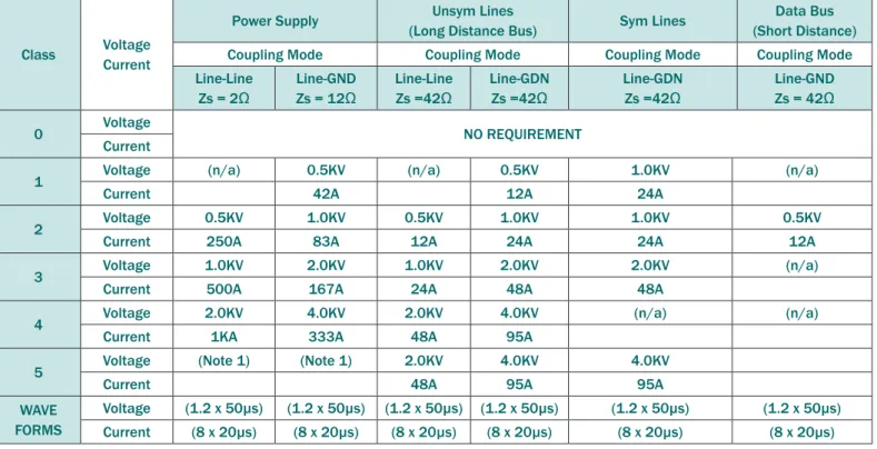
A class 0 environment is considered the lowest threat level and has no transient stress requirements. The class 5 environment is the most severe and requires the highest transient stress level testing. Table 3 summarizes threat levels as a function of installation class. Values of voltage stress using the 1.2 x 50μs waveform are given. Corresponding current values are calculated by dividing the open-circuit voltages by the source impedances. The short-open-circuit current values are more useful in choosing a suppression element.
The short circuit current stress levels are defined with the 8 x 20μs waveform for power supply applications with a 2Ω source impedance. For data lines requiring a 42Ω source impedance, the short-circuit current waveform is defined as 8 x 20μs. For telecommunications applications, the open-circuit voltage is defined as 10 x 700μs and the short-circuit current is a 5 x 300μs waveform. The source impedance is given as 40Ω.
The type of suppression element needed for IEC 61000- 4-5 class surges depends upon the threat level and installation class. For power supply applications high power devices are required. A discrete device or an assembly may be required depending on the application. TVS diodes are the best choice for data line applications and secondary board level protection because of their superior clamping voltage characteristics and fast response time.
Class Voltage Current
Power Supply (Long Distance Bus)Unsym Lines Sym Lines (Short Distance)Data Bus
Coupling Mode Coupling Mode Coupling Mode Coupling Mode
Line-Line Zs = 2Ω Line-GND Zs = 12Ω Line-Line Zs =42Ω Line-GDN Zs =42Ω Line-GDN Zs =42Ω Line-GND Zs = 42Ω 0 Voltage NO REQUIREMENT Current
1 Voltage (n/a) 0.5KV (n/a) 0.5KV 1.0KV (n/a)
Current 42A 12A 24A
2 Voltage 0.5KV 1.0KV 0.5KV 1.0KV 1.0KV 0.5KV
Current 250A 83A 12A 24A 24A 12A
3 Voltage 1.0KV 2.0KV 1.0KV 2.0KV 2.0KV (n/a)
Current 500A 167A 24A 48A 48A
4 Voltage 2.0KV 4.0KV 2.0KV 4.0KV (n/a) (n/a)
Current 1KA 333A 48A 95A
5 Voltage (Note 1) (Note 1) 2.0KV 4.0KV 4.0KV
Current 48A 95A 95A
WAVE FORMS
Voltage (1.2 x 50µs) (1.2 x 50µs) (1.2 x 50µs) (1.2 x 50µs) (1.2 x 50µs) (1.2 x 50µs) Current (8 x 20µs) (8 x 20µs) (8 x 20µs) (8 x 20µs) (8 x 20µs) (8 x 20µs)
Note 1: Depends on class of local power supply system.
Summary
Any OEM equipment manufacturer who plans to sell in the European market will have to meet the requirements of IEC 61000-4. IEC defines three transient immunity standards which provide equipment suppliers with a susceptibility level. Designing in accordance to the IEC standard enables manufacturers to produce more reliable products. Each of the transient immunity standards defines transient sources, entry paths into a system, severity levels, and test methods. Equipment application will determine what level of transient protection is needed. Transient suppression devices must be carefully chosen for each of the standards.
References
Makowski, Leo P., “IEC 1000-4-X (801) Series of Standards,” EMC Test & Design, October 1994 Clark, O.M., “Electrical-Transient Immunity: A Growing Imperative for System Design,” Electronic Design, January 23, 1992
IEC Publication 1000-4-2 “Electromagnetic Compatibility for Industrial Process Measurement and Control Equipment - Part 4, Electrostatic Discharge Requirements,” International Electromechanical
Commission, 1995
IEC Publication 1000-4-4 “Electromagnetic Compatibility for Industrial Process Measurement and Control Equipment - Part 4, Electrical Fast Transient/ Burst Requirements,” International Electromechanical Commission, 1995
IEC Publication 1000-4-5 “Electromagnetic Compatibility for Industrial Process Measurement and Control Equipment - Part 4, Surge Immunity Test,” International Electromechanical Commission, 1995
Lightning Surge Immunity per Telcordia GR-1089
Telephone companies and exchange carriers have long recognized the disruption and equipment damage that lightning induced transients can cause to equipment connected to their networks. To insure safe and continued network operation, telecommunications carriers have required the equipment that they purchase to undergo surge immunity testing designed to emulate the worst case conditions that can be expected in the field. Telcordia GR-1089 is the immunity standard which applies to telecommunications equipment in North America. Telcordia GR-1089 represents the most stringent of lightning immunity standards used for equipment compliance. The GR-1089 standard contains immunity requirements for both inside and outside plant network equipment and customer premises equipment which will be used in carriers networks.
Lightning Immunity
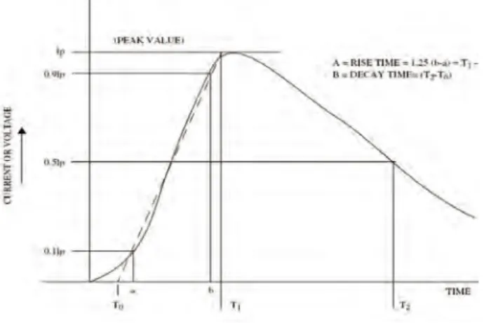
Lightning immunity tests are performed for equipment which is installed either on inside lines only or outside lines. These tests are the result of more than 30 years of field studies measuring actual lightning events in the United States. The studies found that lightning strikes in close proximity produced the fastest rise times, while distant strikes produced slower, longer lasting strikes. The actual shape of the waveforms also varied but Telcordia settled on a double exponential waveform as being representative of lightning surges. The double exponential surge waveform is shown in Figure 1. The double exponential waveform is defined as having an exponential rate of rise to the peak and an exponential decay from that peak.
First Level & Second Level Criteria
GR-1089 specifies two levels of surge immunity. First level tests call for metallic (line-to-line) and longitudinal (line-to-ground) surges. After the first level test, the equipment must function correctly and should not have any degraded performance.
Depending upon the equipment port type, second level surge testing may also be applied. Compliance to the second level criteria requires that the EUT may be damaged but must not become a fire, fragmentation, or safety hazard.
GR-1089 Port Types
GR-1089 categorizes telecommunications ports into various port types based upon the equipment location electrically within the network. As the surge threat is a function of the port location within the network, different levels of immunity testing may be required depending upon the port type. The latest revision of the GR-1089 standard (Issue 4) calls for 8 different port types as shown in Table 1:
Type
Number
Definitinon
Example
Type 1 Directly connected to metallic outside plant (OSP) Broadband coax Type 2 Not directly connected to metallic outside plane (OSP) Ethernet Type 3 Ports directly connected to metallic OSP cable conductors Remote terminals Type 4 connected to metallic outside-plantEquipment port(s) not directly NIUs, ONTs, broadband coax communication Type 5 Cable conductors DSL, remote terminals Type 6 Ports directly to connected to external antennas Cellular service equipment Type 7 Connection to AC power systems
Type 8 Connection to DC power source
Figure 1 – Double Exponential Surge Waveform
First Level Intra-Building Surge - One or Two Pair Ports
Surge Minimum Peak Voltage (Volts) Current (Ampere)Minimum Peak Pulse Waveshape Line-to-Ground Surge?Line-to-Line Surge or
1 ±800V 100A 2/10μs Line to Line
2 ±1500V 100A 2/10μs Line to Ground
First Level Intra-Building Surge - Multi-Pair Ports
Number of Pairs Surge Minimum Peak Voltage (Volts)Value for External Non-Inductive
Resistors
Pulse Waveshape Line-to-Ground Surge?Line-to-Line Surge or
1 or 2 1 ±800V 6 Ω
The combination of 1.2/50μs open-circuit voltage
wave-shape and 8/20μs short circuit current waveshape with
a 2Ω internal impedcance
Line to Line
2 ±1500V 10 Ω Line to Ground
3 or 4 1 ±800V 6 Ω Line to Line
2 ±1500V 20 Ω Line to Ground
Greater than 4 1 ±800V 6 Ω Line to Line
2 ±1500V 40 Ω Line to Ground
Table 2 – First Level Intrabuilding Surge – One or Two Port (Port Types 2 & 4)
Table 3 – First Level Intra-building Surge – Multiport (Port Types 2 & 4) To see how the surge test would be applied, consider the case of
testing a system with port types 2 & 4 defined by GR-1089. Examples for port types 2 or 4 would include Intrabuilding Ethernet or T1/ E1 lines that run within the central office building environment. For this case, there is only a first level lightning surge requirement; the second level surges would not apply.
For a T1/E1 interface, an ±800V (100A) 2/10µs line-to-line pulse and a ±1500V (100A) 2/10µs line-to-ground pulse per the standard is required. It is worth noting, GR-1089 Issue 4 makes a subtle distinction between one or two port systems and multi-port interfaces. For instance, 100Base-T Ethernet would be classified as a two port interface while 1000Base-T Ethernet would be a four-port interface. The surges for these respective cases are shown in the Tables 2 & 3. The following section on Gigabit Ethernet will explore protecting Gigabit Ethernet PHYs against GR-1089.
Transient Voltage Protection for
Gigabit Ethernet PHYs
Ethernet systems within the communications infrastructure are subject to high-level transient threats. This type of equipment may even need to meet the surge immunity requirements of Telcordia GR-1089. Reliable protection of the Ethernet transceiver requires a device that can absorb the expected transient energy, clamp the incoming surge to a safe level, and yet remain transparent to the system under normal operation. Additionally, each new generation of Ethernet deployment yields higher-density boards that demand protection solutions that occupy less board space. Exacerbating the problem, Gigabit Ethernet systems must be rated to operate at high temperatures, making application of external protection even more challenging. This section will discuss a solution for providing reliable protection of GbE systems. This solution is designed to meet the surge requirements of GR-1089. If designed properly, this solution can be used without causing transmission errors.
Transient Threats
The small geometries of GbE transceivers make them particularly susceptible to upset or damage from transient events. One of the most common threats is a Cable Discharge Event (CDE). A CDE occurs when an Ethernet cable becomes charged (due to interaction with its environment) and subsequently discharges into the circuit when the cable is plugged into the connector. In general, the waveforms last for a few hundred nanoseconds with rapid polarity changes. Electrostatic discharges (ESD) that originate from the user are also common. These types of waveforms last for approximately 60ns and are consistent with the human body model
as defined by immunity standards such as IEC 61000-4-2. For outside connections, lightning can also induce high voltage surges onto the communication lines that connect to the Ethernet PHY IC. These events are high energy pulses, lasting several microseconds. The Telcordia Technologies GR-1089-CORE specification defines a set of requirements for lightning and ESD immunity for intra-building equipment. The lightning tests are applied as metallic (line-to-line) or longitudinal (line-to-ground) waveforms. The waveforms are defined with a rise time of 2µs and a decay time of 10µs with an open circuit (metallic) voltage of 800 volts short circuit current of 100A. Positive and negative polarity surges are applied. To pass, the equipment must continue to operate after the test.
Ethernet Magnetics
An Ethernet port includes transformers and common mode chokes for connecting the PHY to the outside world. Transformers and chokes can be discrete components, but integrated solutions that include the RJ-45 connector, resistors and capacitors are becoming increasingly popular. In either case, the transformer will provide a high level of common mode isolation to external voltages, but no protection for metallic surges. For a metallic (Line-to-Line) surge, current will flow into one line, through the transformer and back to the source. As the current flows, it charges the windings of the transformer on the line side ( RJ45 side). Once the surge is removed, the windings on the line side will stop charging and will transfer its stored energy to the IC side where the PHY IC is located. Regardless, the pulse will most certainly be destructive to the PHY chip.
Ethernet PHY RJ-45 TP1+ TP1-TP2+ TP2-TP3+ TP3-TP4+ TP4-RClamp2504N RClamp2504N RClamp2504N RClamp2504N 1 2 3 4 5 6 7 8
Protection Solutions
As the feature sizes on performance PHYs are scaling smaller along with thinner oxide layers, using low working voltage TVS is critical to safeguarding Ethernet PHYs. Semtech’s RClamp2504N is a low capacitance, transient voltage suppressor (TVS) designed to protect Gigabit Ethernet ports while maintaining traffic performance over temperature. The RClamp2504N is constructed using Semtech’s low-voltage EPD process technology to achieve a low working voltage of 2.5 volts. The RClamp2504N circuit diagram is shown in Figure 1. The device is in a leadless, RoHS compliant package measuring 2.6 x 2.6 x 0.6mm. The RClamp2504N’s low 2.5V working voltage results in a low clamping voltage for maximum protection of the GbE PHY. The RClamp2504N may be used on the PHY side of the transformer to meet the Intra-building surge requirements of Telcordia GR-1089 (Ipp=100A, tp=2/10µs).
Figure 1 illustrates a protection solution using the RClamp2504N TVS device for protecting a Gigabit Ethernet PHY. The four line pairs are protected using the RClamp2504N connected in differential mode (line-to-line) on the PHY side of the transformer. For optimal performance, parasitic inductance should be minimized by placing the device as close to the magnetics as possible and on the same side of the board as the PHY. The clamping voltage, measured at 10.8V, for a metallic mode 800V (100A) 2/10µs surge provides sufficient clamping margin to minimize electrical stress and prevent latent failure.
GbE System Operation over Temperature
Depending upon the operating environment, Telecom and Datacom systems may be exposed to harsh temperatures extremes. Ethernet ports within these systems are required to operate at very high temperatures. In addition, the IEEE 802.3 specification requires that the Ethernet interface supports data transmission on cable lengths of up to 100 meters. A long cable length will present an additional load to the system transmission, and at elevated temperature, symbol or CRC (Cyclical Redundancy Check) errors can result. Thus, an Ethernet protection circuit must provide the clamping performance to arrest the GR-1089 surge, while also residing on the Ethernet interface without introducing traffic errors.
Generally, the Ethernet interface should provide error free transmission up to 65ºC with a 100m cable attached to the port. This presents several challenges. First, the high temperature means the margin of operation of the PHY will be reduced. Secondly, the 100 meter cable presents a large load on the receiving end. Finally, the protection component will present non-linear impedance over temperature. The GbE PHY can account for some impedance variations or discontinuities on the line by performing a forward error correction (FEC). However, large non-linear impedance changes across the differential pair can not always be accounted. The amount of variation in the protection device will depend on leakage current and capacitance; factors dictated primarily by the junction area of the device. Semtech TVS devices have been shown to operate on Gigabit Ethernet interfaces without introducing pocket errors. Figure 2 – RClamp2504N Circuit Diagram