Materials, mold making and injection
molding for 3D-MIDs
Dr. Christian Goth and Thomas Heimann
The injection molding process offers superior design freedom, which in turn opens up MID technology's great potential to implement three-dimensional packages. HARTING Mitronics commands extensive experience in one and two component injection molding. The injection molds are developed, designed and manufactured according to the customer's design specifications based on MID design guidelines. Micro-precision molds can also be
manufactured in the HARTING Technology Group's own mold manufacturing area.
1 Materials
Instead of the duroplastic or ceramic substrate materials employed in conventional PCB technology, MID technology uses thermoplastics, although the first duroplastic LDS materials are now available. Thermoplastics are built up from linear, to some extent slightly branched, macromolecules that are connected only by weak physical bonds. At higher temperatures these can slide past one another, which means that they are meltable and plastically formable. In the solid state, thermoplastics can be amorphous or semi-crystalline (Figure 1).
Figure 1: Plastic pyramid with amorphous and semi-crystalline MID materials
Amorphous plastics are employed below the glass transition temperature (Tg). Semi-crystalline materials, on the other hand, can also be used at temperatures above Tg. Below Tg the amorphous portion is solidified and the plastic is hard and brittle. The crystalline areas, which are kept until the melting temperature is reached,
Amorphous Semi-cristalline Standard plastics Engineering plastics High performance plastics LCP PEEK PPS PC PET PBT PA66 PA6 PEI PPA ABS PPE
Materials, mold making and injection
molding for 3D-MIDs
Dr. Christian Goth and Thomas Heimann
determine the mechanical properties above Tg. [2] The materials LCP, various PA types, PBT, PC, PC/ABS, PEEK, PET/PBT, PPA and PPE are fundamentally available for laser direct structuring (LDS), and virtually all materials can be prepared with the LDS additive. [3] Two component injection molding can be carried out with such material combinations as LCP/LCP, PC/PC-ABS and PC/ABS, to name a few. The whitepaper Laser direct structuring and two-component injection molding for series MID production provides additional information on the specific requirements for LDS and 2-shot materials. HARTING Mitronics currently relies on the materials LCP (LDS and 2-shot) and PBT (LDS) for series production. Tests are currently underway with the materials PC/ABS for high mechanical demands at low costs, various PA types for economical SMT applications, and PPSU for medical applications (including when there is a demand for autoclavability). Furthermore, new high performance thermoplastics (e.g., PEEK), LDS duroplastics, and LDS ceramic materials are being developed. LCP is chosen as the substrate material for the majority of series applications (with the exception of simple antenna applications). LCP features excellent thermal characteristics and is suitable for convection and condensation soldering. It has thermal linear expansion coefficients that are lower than those of most other thermoplastics and that are virtually comparable to those of standard PCB materials. LCP is a liquid crystal polymer that can be used to implement extremely long flow paths in applications with thin walls. Two-component injection molded parts can be manufactured without burr formation and overmolding. Because the adhesion of LCP to LCP tends to be low, design measures must be used to solve the connection of the two components. [8]
2 Mold making
The HARTING Technology Group has its own mold making area for micro-precision molds with extensive and safeguarded experience, as well as fully automatic CNC-controlled metal processing machines. The molds are designed in close coordination with the customer and according to the customer's specifications.
2.1 Basic mold making for MIDs
The design guidelines specific to MIDs must be observed during mold making in order to manufacture components with quality that meets the demands of the subsequent processes. HARTING Mitronics has developed its own design rules for laser direct structuring and two-component injection molding technologies. The LDS-MID Design Rules from LPKF Laser & Electronics AG are also available. The general design
conditions for mold making are explained in detail in the paper Development and design of 3D-MIDs. [4] [5] [7] During the mold design it must be ensured that there is no spraying in areas that will later be given conductor paths. There should also not be any ejection points in these critical areas. Where possible, a hot runner system in which the nozzle and mold are constantly in contact should be chosen as the gating system. The waste can be minimized by choosing gateless injection. Sprue or film gates should be avoided where possible because there is a risk of foreign deposits in the area of the breaking or shearing edges due to mechanical activation of the plastic component during the subsequent metallization. However the time the thermoplastic spends in the spiral and in the hot runner is not permitted to be too long because otherwise the material can show signs of decomposition. Therefore a gate is deliberately generated in order to increase the material flow rate, particularly for small parts. The flow rate can also be increased, however, by a mold with a number of cavities, particularly when there are large production runs. When producing small molded parts in multi-cavity molds (up to 16), HARTING Mitronics frequently uses a tunnel gate. A tunnel gate is a self-separating gating system. The gating
Materials, mold making and injection
molding for 3D-MIDs
Dr. Christian Goth and Thomas Heimann
system's diameter should be chosen to be as small as possible in order to allow a clean tear. The material for filling the mold must pass through this system, however, and openings that are too small can lead to thermal damage to the material due to excessively high shear rates. In the case of multi-cavity molds, it should be ensured that the melt state is identical in all mold cavities and it should be kept in mind that a tempered distribution duct may be necessary.
Before developing the mold concepts and constructing a prototype or series mold, HARTING Mitronics reviews the feasibility and estimates the costs for the prototype mold and series mold based on the customer request. The mold design can be safeguarded by appropriate FEM calculations, mold flow analyses, 3D-CAD
calculations and thermal analyses for the mold. In this connection, the component may also be optimized, for example, with regard to draft angles or burr formation.
2.2 Prototype and series molds
In most cases, it is necessary to prepare prototypes in order to finally specify the molded part's dimensions. HARTING Mitronics offers customers various sample levels (visually representative samples and A, B, C and D samples) with various manufacturing technologies. The whitepaper Prototyping for 3D-MIDs provides more information on this subject.
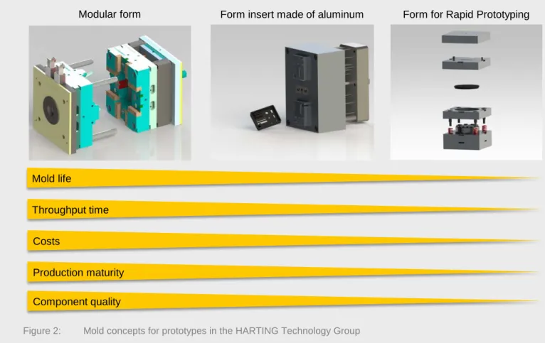
In the HARTING Technology Group, a 3-step model is defined for the prototypes that are tied to the mold. The individual steps here differ with regard to the mold life, throughput time, costs, production maturity, and component quality (Figure 2).
Materials, mold making and injection
molding for 3D-MIDs
Dr. Christian Goth and Thomas Heimann
Figure 2: Mold concepts for prototypes in the HARTING Technology Group
Only the nozzle and ejector insert sets are required for the modular form, which is available throughout the HARTING Technology Group. The system with integrated tempering is suitable for high mold lives with batch sizes greater than 1,000 pieces. Here, it is possible to use series-identical materials and surface qualities for the form inserts. There are no limitations for the workable plastics.
A form insert made of aluminum can also be integrated into the modular form and can optionally be executed with or without tempering. The limitation to milling when producing the cavities translates as significant cost reductions, but the molds are only suitable for batch sizes of up to around 1,000 pieces and are limited to small geometries when it comes to the reproduction accuracies.
The form for rapid prototyping is also made by means of machining involving milling. This is a platform for batch sizes less than 100 parts with a throughput time (depending on the complexity of the component geometry) of one week, calculated from the data receipt until the first parts. The mold dispenses with tempering and provides no ejectors, so that manual part removal is required. The components generally have more burr formation and less geometric precision. The suitability for MID prototyping is currently being reviewed at HARTING Mitronics.
Modular form Form insert made of aluminum Form for Rapid Prototyping
Mold life
Throughput time Costs
Production maturity Component quality
Materials, mold making and injection
molding for 3D-MIDs
Dr. Christian Goth and Thomas Heimann
Series molds are not made of aluminum in order to avoid foreign deposits from the mold during metallization. For series production, a system with hardened tool steel is used (Figure 3). Here a standard surface quality (RZ < 5 μm) is sufficient, and the surface does not normally need to be polished. [7]
Figure 3: One-component injection mold with four cavities for a 3D-MID
Usually a turning tool is employed for two-component injection molding. The primary molded parts are conveyed into a second cavity after the mold is opened by turning one mold half or by means of a turning index plate. Alternatively, it is also possible to use a mold with a variable cavity, where first the primary molded part is made and then a slide or retracting core is used to open an additional volume in the cavity for the second component (core back mold). In this case, however, the design freedom is limited. Transfer techniques in which the primary molded part is completely removed and then the injection takes place in another mold are generally
uneconomical due to the complex handling.
3 Injection molding
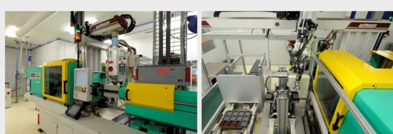
In injection molding, the plastic granules are plastified (dissolved by heating) and injected with pressure into a heated mold cavity as a fluid mass. After solidification, the injection molded part must be demolded and removed. In general, the process flow in MID technology does not differ from that of conventional plastic processing, but some special issues must be kept in mind with regard to further processing. Figure 4 shows an injection molding machine used to manufacture MID substrates. For high quality in the downstream process steps and for a component with long-term reliability, the injection mold parts are not permitted to exhibit any cracks, burrs, blistering, burn marks, shiny spots, streaks, or sink marks [4] [5]. This requires the appropriate
Materials, mold making and injection
molding for 3D-MIDs
Dr. Christian Goth and Thomas Heimann
preparation of the materials, observance of influences related to the manufacturing, and adapted processing after the injection molding process.
Two-component injection molding is a special form. Here, the first step is to make a primary molded part, which is then immediately overmolded. Depending on the geometric form of the part, the component that is more mechanically stable is injected first (this part can be either the metallizable or the non-metallizable component). In 2-shot technology, the circuit layout is based on the geometric form of the injection molding mold. Therefore there are only limited possibilities for further miniaturization, particularly since the flow paths of the second component are too thick if the walls are thin. The smallest conductor path widths are possible with low viscosity molding materials such as LCP.
Figure 4: Arburg injection molding machine (left) and automated part handling with deposit in plastic blister (right)
3.1 Material preparation
Plastic manufacturers usually deliver plastic granules in 25-kg containers. Before the material processing, the granules must be dried because many thermoplastics absorb moisture. As a result, processing when the granules are not dry can result in manufacturing errors such as streaks, haze, or blistering in the component that then can cause problems in subsequent processes, particularly during the structuring, metallization and soldering. At HARTING Mitronics, a filling hopper with pre-heating and drying equipment is used directly at the injection molding machine. Here, the residual heat of the dried plastic granules can be used during the
Materials, mold making and injection
molding for 3D-MIDs
Dr. Christian Goth and Thomas Heimann
3.2 Influences resulting from the manufacturing
When producing MID molded parts, influences resulting from the manufacturing such as joint lines, burr formation, increased anisotropies or a change in the dimensions due to shrinkage should be avoided where possible, or it should be ensured that these are not in critical areas. In order to reduce the environmental influences on the manufacturing process, the MID substrates are injection molded in an air conditioned area at HARTING Mitronics. The molds are carefully cleaned before and during the injection molding process in order to avoid contamination. The mold's cleaning intervals are defined according to the specific article. The use of silicon-based mold release agents and lubricants for ejector pins is avoided when possible.
A joint line forms where flow fronts come together, for instance, after flowing around holes or due to differences in the wall thickness. Unlike joint lines that form due to frontal convergence of melt flows, flow lines result from flows that run in parallel. Flow lines can result from different flow rates or they can be the result of flowing around a core. Joint lines and flow lines result in mechanical impairment of the molded part due to insufficient welding, incidence notches in the surface or strong orientations when there are melt fronts that flow into one another in parallel. The formation of joint lines is particularly critical with LCP. In general, it should be ensured that no conductor paths run in the area of joint lines whenever such lines cannot be avoided (Figure 5). Otherwise cracks can develop in the conductor path if there are mechanical of thermal loads. [2] [7]
Figure 5: Conductor paths should not run close to joint lines or ejector pins [3]
When the two mold halves are separated, a burr may develop due to overmolding. This can cause a premature malfunction, particularly if the burr runs perpendicular to the conductor path. The slightest possible burr
formation can be achieved by means of reduced injection and holding pressure, a greater closing force, and optimally coordinated mold separation planes.
Concentrated molecular orientation can reinforce the anisotropy, which is pronounced with fiber-reinforced thermoplastics in any case. Elongation flows in the melt here lead to stronger orientation than shear flows do [1]. The molded part's geometry and the processing conditions should therefore be adapted accordingly. Jetting is another factor that should be avoided. A jet of material develops when the melt shoots unchecked into the form at too high a speed. However this can be avoided by properly positioning the spraying point. Shortly after entering the cavity, the melt should hit a wall or a core.
The dimensional stability of molded parts that are made of plastic is often influenced by shrinkage during processing and use. A distinction is made between processing shrinkage and post-shrinkage. Processing shrinkage describes the difference between the dimensions of the mold and that of the molded part.
Post-Position of ejector pin
Materials, mold making and injection
molding for 3D-MIDs
Dr. Christian Goth and Thomas Heimann
shrinkage leads to a further change in the component's dimensions with an impact on the conductive pattern that can be negative. Some factors that can influence shrinkage are the melting temperature, the mold wall temperature, the holding pressure and the wall thickness. [1]
3.3 Further processing after the injection molding process
During component removal and transport appropriate precautions should be taken in order to ensure that the components and their surfaces are not adversely affected. At HARTING Mitronics the MID parts are placed into deep draw plastic blisters for further processing in later steps in order to avoid scraping the components (Figure 4). For certain articles, additional intermediate cooling is integrated into the manufacturing process after the injected molding part is removed from the mold and before it is stored in order to prevent thermal damage to the transport container. The people involved in the manufacturing process wear gloves in order to avoid
contaminating the component surface. [4] [7]
Authors
Dr.-Ing. Christian Goth is active at HARTING Mitronics as Strategic Technology Manager. He earned his doctorate at the Universität Erlangen-Nürnberg with a paper on the topic "Analysis and Optimization of the Development and Reliability of Spatial Electronic Interconnect Devices (3D-MID)" under the direction of Prof. Franke in the professorship for manufacturing automation and production systems. From 2007 to 2011 he was executive director of Forschungsvereinigung Räumliche Elektronische Baugruppen 3-D MID e.V.
Thomas Heimann is head of the Technology Development area at HARTING Applied Technologies GmbH. He studied general mechanical engineering at the Hochschule Osnabrück. After graduating Mr. Heimann first worked as a development engineer at HARTING Automotive GmbH for seven years, and was entrusted with the development of connectors and plastic housings for the automotive industry. He then moved to HARTING Applied Technologies GmbH, where some of his responsibilities include mold and plastic implementation for MID projects.
Bibliography
[1] EHERENSTEIN, G. W. (Publisher.): Mit Kunststoffen konstruieren – Eine Einführung. 3. überarbeitete Auflage. München Wien: Carl Hanser Verlag, 2007.
[2] EHERENSTEIN, G. W. (Publisher.): Polymer-Werkstoffe – Struktur, Eigenschaft, Anwendung. 2. völlig überarbeitete Auflage. München Wien: Carl Hanser Verlag, 1999.
[3] JOHN, W.: Fertigungsgerechte Konstruktion dreidimensionaler Schaltungsträger. In: Produktion von Leiterplatten und Systemen (PLUS) 10. Jahrgang, Nummer 6 (2008), S. 1259-1263.
[4] HARTING AGMITRONICS (PUBLISHER.): Design Guidelines: MID-LDS., Version 1.2, as of 30 Sep. 2009. [5] HARTING AGMITRONICS (PUBLISHER.): Design Guidelines: MID-2K. Version 1.2, as of 30 Sep. 2009.
[6] LPKF LASER & ELECTRONICS AG (PUBLISHER.): Approved plastics for the operation of LPKF LDS Laser Systems. File: http://www.lpkf.de/_mediafiles/2074-approved-plastics-lds.pdf, last revised: December 2012, access on 6 March 2013.
Materials, mold making and injection
molding for 3D-MIDs
Dr. Christian Goth and Thomas Heimann
[7] LPKF LASER &ELECTRONICS AG(PUBLISHER.): LDS-MID Design Guide – Technical Information. Version 2.0, as of Nov. 10, 2010, Garbsen, 2010.
[8] SCHMID, B.: Leiterplatte und Leiterbahnen im Spritzguss. In: Elektronik – Sonderausgabe Räumliche elektronische Baugruppen 2011, S. 9–11.
Glossary
Technical terms
Abbreviation Term Explanation
Contamination Soiling or pollution with chemical, biological or radioactive material.
MID Molded Interconnect
Device
Injection-molded molded part with integrated conductive structure and components (optional).
Tg
Glass transition temperature
Transition from energy elastic area (= glass range) to the soft entropy elastic area (= rubber elastic range).
Mean surface
roughness Rz
The arithmetic mean of the individual roughnessess of five equidistant adjacent individual measurement sections.
List of abbreviations
2K Two-shot (two-component) 3D Three-dimensional
ABS Acrylonitrile butadiene styrene CNC Computerized Numerical Control FEM Finite Element Method
LDS Laser Direct Structuring
PA Polyamide
PBT Polybutylene terephthalate PC Polycarbonate
PEEK Polyether ether ketone PET Polyethylene terephthalate PPA Polyphthalamide

![Figure 5: Conductor paths should not run close to joint lines or ejector pins [3]](https://thumb-us.123doks.com/thumbv2/123dok_us/976883.2628166/7.892.99.781.650.783/figure-conductor-paths-close-joint-lines-ejector-pins.webp)