G u a rd l o c k i n g s y s t e m s f o r
Möddinghofe 30 D - 42279 Wuppertal P.O. Box 24 02 63 D - 42232 Wuppertal Germany Phone +49 - (0)2 02 - 6474- 0 Fax +49 - (0)2 02 - 6474- 1 00 E-Mail [email protected] Internet www.schmersal.com
Elan Schaltelemente GmbH & Co. KG Im Ostpark 2 D-35435 Wettenberg Germany Phone +49 (0)641 - 9848 - 0 Fax +49 (0)641 - 9848 - 420 E-Mail [email protected] Internet http://www.elan.de
3
Table of contents
Introduction
Operator and process safety
Page
4
Installation and operating solenoid interlocks
Page
5
Product
1. Solenoid interlock devices
Page 15
2. Door handle switch
Page 22
3. Safety control modules
Page 24
4. Fail-safe standstill monitors
Page 26
5. Wiring diagrams
Page 29
6. Terminal definition
Page 53
Appendix
7. Glossary
Page 54
8. Symbols
Page 58
This brochure contains a short overview of the indi-vidual product lines and the main accessories avail-able within the Schmersal Group for guard locking applications.
The technical data for the individual devices are complemented by wiring diagrams, which show how simply Schmersal components can be wired together into a complete system.
In addition, solenoid inter-locks can also help meet the safety requirements defined in EN 1037, i.e. the protection against unexpected start-up of machinery.
The Schmersal Group of-fers its customers the largest program of safety control systems for the protection of man and ma-chine, in particular a large range of solenoid inter-locks and intelligent ac-cessories that facilitate the integration of solenoid in-terlocks into the user’s ap-plication.
The program includes door handle switches, mounting sets and a large range of actuators, suitable even for small actuating radii. Together with fail-safe standstill monitors and safety control modules, complete system solutions can be configured. Most machine guarding
on industrial machinery is fitted with guard-locking safety interlocks (solenoid interlocks). This has two reasons:
Firstly, EN 1088 requires that hazardous areas on machinery and plant re-main inaccessible until all dangerous machine move-ments have stopped. This can be achieved by in-stalling a solenoid interlock on movable machine safe-ty guards.
Secondly, solenoid inter-locks also serve to safe-guard the process: any unauthorised intervention in the running processes or any unexpected ma-chine stop by an unfore-seen opening of a safety guard is avoided. For ex-ample, a solenoid interlock can ensure that a robot completes its entire cycle before it stops. Moreover, solenoid interlocks can prevent damage to a ma-chine tool through an un-expected stop, thus help-ing to ensure maximum productivity.
5
Installation and operating solenoid interlocks
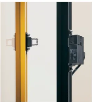
Fig. 1: Solenoid interlock AZM 170 with separate actuator
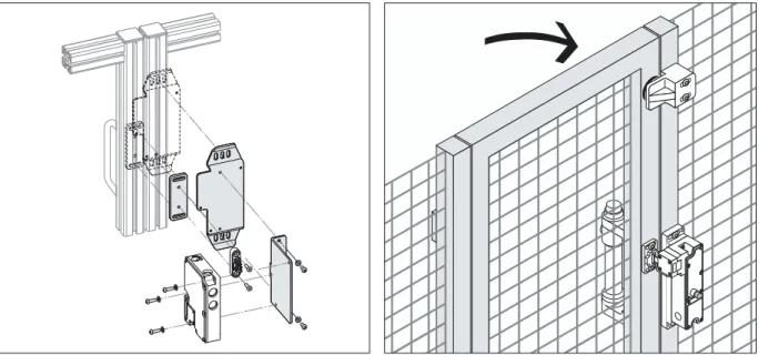
The Schmersal guard-locking safety interlocks are based on the principle of the “separate actuator” (Fig. 1):
The actuating element (the actuator or “key”) is fitted to the movable part of the machine guard (usually a safety guard). The solenoid interlock itself is mounted to the stationary part of the guard, for example the door post. The machine can only start when the actuator (mounted on the moveable guard) has en-tered the solenoid interlock and is locked in position.
To optimise the benefits of this principle, some basic rules for the design of the machine guard and inter-lock mounting, as well as during machine operation, must be observed. The following pages contain practical hints and advice on mounting and operat-ing solenoid interlocks.
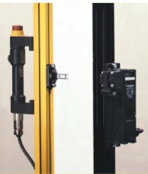
Fig. 3: Positioning of the solenoid interlock and door handle on a safety guard
Fig. 2: Door handle switch TG with AZM 190
Solenoid interlocks should be fitted near the door handle
For trouble-free guard locking, it is imperative that the actuator smoothly enters the solenoid inter-lock throughout the guard´s intended lifetime. To achieve this, the safety guard must have a degree of stability that does not allow torsion or door-setting.
In addition, it is recom-mended to fit the safety guard handle as close as possible to the solenoid in-terlock. This ensures that the actuator can always be easily extracted or inserted into the solenoid interlock, even in case of a de-formed or distorted safety guard (see Fig. 3).
7
Fig. 5: Fixed and flexible actuator End stop – for heavy
safety guards fit a damper against rebound
The solenoid interlock must not be used as me-chanical end stop or as a guide for the safety guard. A separate end stop is re-quired. Even with an end stop, the rebound from a heavy safety guard can lead to serious damage to the solenoid interlock and/ or actuator if, upon closing the door, the solenoid latches the actuator into the locked position. To prevent this, a damper can be fitted to the door.
All in one:
door handle switch TG
For larger machines and assembly lines which have many safety guards, a separate unlocking button should be fitted near or on each safety guard to enable individual guard unlocking. In this way, the operator does not need to go to the machine control panel and unlock all safety guards; but can unlock and lock only the safety guard re-quired.
The door handle switch TG developed by the Schmersal Group features a door lock control button with integrated LEDs to in-dicate if the safety guard is locked or released. This ergonomic aspect helps deter the operator from prematurely pulling on the door and jamming the un-locking mechanism. An emergency stop button can also be integrated into the door handle switch where required (Fig. 2).
Actuator: fixed or flexible?
The size of a hinged guard can limit the operating ra-dius of the actuator. To guarantee smooth inser-tion of the actuator into the solenoid interlock in such cases, the Schmersal Group offers a large range of actuators specially de-signed for small actuating radii. On hinged guards the use of flexible ad-justable actuators is rec-ommended; for sliding guards, fixed actuators are more suitable (Fig. 5).
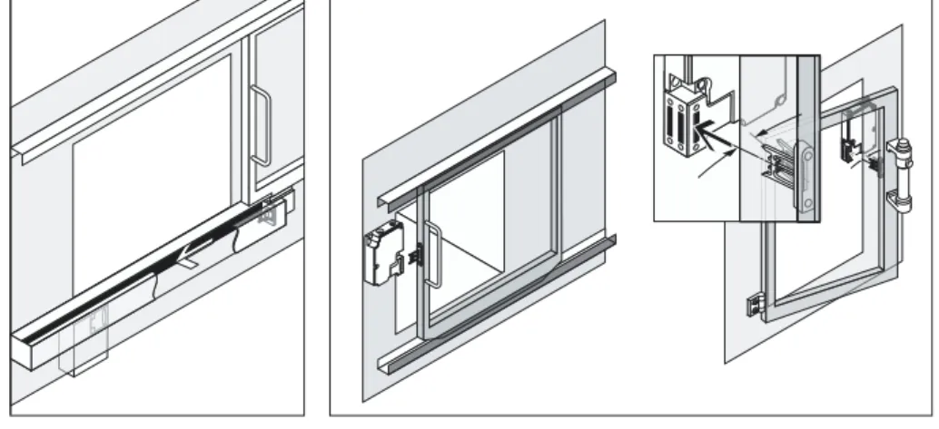
We recommend attaching the actuator inextricably to the safety guard, for exam-ple using one-way screws to avoid the actuator being removed for unauthorised use. As an alternative the actuator can be fitted in a concealed position, which also minimises the risk of injury from the actuator (Fig. 4).
Fig. 4: Concealed mounting
Fig. 7: Power to lock Operating principle:
spring to lock or power to lock?
All solenoid interlocks de-veloped by the Schmersal Group feature a fail-safe locking mechanism. This design feature, described in EN 1088, means that the solenoid locking bolt can only lock after the ac-tuator has entered the in-terlock i.e. the safety guard is closed. This means that the safety cir-cuit can be enabled using the solenoid contacts only. The actuator contacts are used solely for position in-dication of the safety guard.
Since solenoid interlocks featuring a fail-safe locking mechanism offer a higher degree of safety, the in-stallation of a second de-vice for monitoring safety guard position can be left out under certain circum-stances (see page 28).
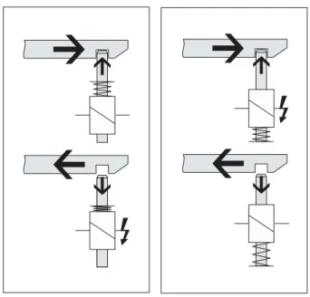
Solenoid interlocks have two different operating principles:
• Solenoid interlocks with spring to lock are locked by spring force and un-locked by energising the solenoid (Fig. 6). • Solenoid interlocks with
power to lock are locked by energising the sole-noid and unlocked by spring force (Fig. 7).
Both principles are com-mon on machine safety guards. For the protection of personnel against haz-ardous stored energy (e.g. run-on), the use of sole-noid interlocks with spring to lock is strongly recom-mended.
Solenoid interlocks with power to lock may only be used in special cases after evaluating fully all the haz-ards, since in case of power failure or machine power switch off, the guard can be opened im-mediately and the operator exposed to the hazard.
On the other hand, solenoid interlocks with power to lock are suitable for ma-chine and/or process safety.
This type of solenoid inter-lock can deter the opera-tor from interrupting a run-ning process and, for ex-ample, avoiding damage to machine tools. The power to lock princi-ple enables fast access into the machine in case of failure – when the machine power is switched off the safety guard can be un-locked. Using a solenoid interlock in this way can help optimise the machine productivity.
Fig. 6: Spring to lock
9
Fig. 8: Mounting kits simplify the fitting of solenoid interlocks Fig. 9: Simple but effective mounting of the AZM 190 due to its special housing design
Mounting sets simplify fitted
Schmersal has developed mounting sets to enable quick and safe fitting of solenoid interlocks and ac-tuators. The mounting sets are suitable for fitting on common steel and alumini-um profile systems and simplify the alignment be-tween actuator and sole-noid interlock (Fig. 8).
The unique housing design of the AZM 190 allows a particularly elegant solution for hinged guards and alu-minium profile systems. The angled actuating head allows the solenoid inter-lock to be mounted inside the hazardous area so that only the head is visible from outside. In addition to the practical advantages, this device can also im-prove the optical impres-sion of the machine – an important factor on mod-ern machines (Fig. 9).
Caution: Pre-tensioned safety guards!
In spite of careful safety guard design, the practice shows that they often be-come deformed, distorted or misaligned during their lifetime. With this in mind, a certain play between the actuator and the solenoid interlock is tolerated by de-sign, so that the safety guard can be displaced from its ideal position.
Safety guards are also pre-tensioned by operators try-ing to open a locked door. This force must not exceed a specific maximum pre-tension force for the sole-noid interlock concerned, otherwise the solenoid will not be able to unlock, and
the door cannot be opened. Schmersal’s patented tog-gle-lever system can with-stand a maximum admissi-ble pre-tension of up to 500 N (AZM 415).
In addition, a specific hold-ing force (the so-called latching force) is present, so that the tensioned guard is held closed even in an unlocked condition.
When selecting the appro-priate solenoid interlock, the maximum permissible holding force on the device in the locked position must be taken into account. Schmersal solenoid inter-locks are available with a holding force of between 1000 N and 3500 N.
Since solenoid interlocks are either locked or un-locked by a solenoid, they require differing solutions for manual unlocking in a power-off condition (for example during installation or maintenance) than for unlocking during machine operation.
Battery-operated release*
When spring to lock sole-noid interlocks are in-stalled in inaccessible or concealed positions, and in the case of power off or failure, the operator is con-fronted with the problem of how he gains access to the machine. In this case, it is useful to provide a separate power supply for the solenoid. This can be a battery-operated release in the control cabinet. The battery is charged during normal operation and in the case of power failure, can be switched on to un-lock the safety guard.
* In preparation
Fig. 11: B30 actuator with integrated emergency handle Fig. 10: Manual release
Manual release
Machinery fitted with spring to lock solenoid in-terlocks normally have a way of opening the safety guard during a power fail-ure, usually by means of a tool such as a triangular key (Fig. 10). The Schmer-sal solenoid interlocks are fitted with such an auxiliary unlocking mechanism, the so-called “manual re-lease”.
Upon operating the manu-al release, the positive break safety contacts are simultaneously opened thus preventing unexpect-ed machine restart.
11
Fig. 14: Solenoid interlock with integrated fail-safe standstill monitor
Fig. 13: Emergency exit or emergency release Emergency release
With an emergency re-lease, the safety guard can be opened from outside the hazardous area with-out the operator using any tool, for example when a fast intervention into the hazardous area is required to guarantee process safe-ty. Unlocking is possible without special tools, re-setting however requires a repair-like intervention.
times – fail-safe delay timers. For these applica-tions, the Schmersal Group has developed a compre-hensive range of fail-safe standstill monitors (Fig. 14). For these types of ma-chine an emergency stop safety control module with delay on de-energisation (stop category 1 to EN 60204-1) must not be used, since the failure mode of the delay function is t = 0. This would result in the safety guard unlock-ing too soon in case of failure.
Standstill monitoring
Solenoid interlocks for personnel protection are used when the time taken to access the hazardous area from the safety guard can be less than the time needed for the hazard to have ceased (i.e. the mov-ing parts have come to a standstill). The safety guard must remain locked until the machine hazard has been reduced to a minimum. In this case, the solenoid interlock can be combined with a fail-safe standstill monitor or – in case of constant run-down
Emergency exit
The emergency exit allows an intentional opening of the safety guard from in-side the machine without tools, for example when personnel are trapped in-side a machine (Fig. 12 and 13).
For this application, the Schmersal Group has de-veloped the AZM 415 and TZFS.NN with emergency release which, used to-gether with a B30 actuator and integrated emergency handle, allow an emer-gency exit from inside a machine guard (Fig. 11).
Fig. 12: Emergency exit
Fig. 14: AZM 415 with B30 actuator
This allows personnel to evacuate the hazardous area easily. By operating the emergency release, the safety circuit of the machine is interrupted and the machine is shut down.
However, in order not to endanger personnel that could be inside the haz-ardous area during the start-up or restart, the fol-lowing aspects have to be taken into account. Hazardous areas of
ma-chinery and plant can be so large, that the machine can be entered completely by personnel.
The Machinery Directive requires that in this case personnel cannot be inad-vertently locked into the hazardous area.
To prevent this situation, solenoid interlocks can be fitted with the emergency exit system described previously.
Fig. 15: Full body access of hazardous areas
13
First of all, the start button must be installed in a loca-tion where the operator has a complete overview of the hazardous area. In addition the start button must not be accessible from inside the hazardous area.
Secondly it is strongly rec-ommended to use a safety control module with a monitored start circuit.
y access
These safety control mod-ules enable only a trailing edge signal from the start button, i.e. they enable when the button is re-leased, not when it is pressed. The trailing edge control module can thus detect a failure in the start button (e.g. contact weld-ing) and manipulation (but-ton held down).
The comprehensive range of safety control modules from the Schmersal Group include monitored start (trailing edge) function.
On machine tools
On guard fencing systems
Typical mounting positions for solenoid interlocks on machine tools
Installation of a solenoid interlock AZM 190 with emergency exit from inside the hazardous area
Installation of a solenoid interlock AZM 161 with emergency exit from inside the hazardous area
Installation of a solenoid interlock AZM 161 on a sliding guard
Installation of a solenoid interlock AZM 415 with emergency exit from inside the hazardous area
15
AZM 170 AZM 161 TZF/TZM AZM 190 AZM 415
Size in mm (B x H x D)
Material Application
Max. holding force
Latching force Contacts
Mounting set Approvals
90 x 84 x 30 130 x 90 x 30 129 x 92 x 41 89 x 178 x 41 130 x 100 x 46,5
Thermoplastic Thermoplastic Thermoplastic Thermoplastic Metal alloy
1000 N2000 N1700 N 2500 N* 2000 N3500 N 30 N30 N30 N30 Nbis 500 N Solenoid: 1NC Actuator: 2NC or 1NO/1NC Solenoid: 1NO/1NC or 1NO/2NC Actuator: 1NO/3NC, 2NO/2NC or 1NO/2NC Solenoid: 1NC or 1NO/1NC Actuator: 2NC or 1NO/1NC Solenoid: 1NO/1NC or 2NC Actuator: 1NC or 1NO Solenoid: 1NO/1NC Actuator: 1NO/1NC
Yes Yes Yes *** Yes Yes ***
BG, UL, CSA BG, UL, CSA BG, UL, CSA BG, UL, CSA BG, UL, CSA
Actuator alignment tolerance
± 2 mm ± 2 mm ± 4 mm ± 4 mm ± 3 mm
Max. actuator play (in locked condition)
4 mm 5 mm 11 mm 5 mm 3 mm
Min. radius for hinged guards 50 mm 95 mm 150 mm 150 mm 250 mm Number of actuating directions 2 3 3 ** 4 1 Page 16 17 18 19 20
* = Only in conjunction with reinforcing bracket TZ-44 ** = 4 upon request
*** = Only in conjunction with B30 actuator
Selection table: Solenoid interlocks
AZM 170➀-➁zrk➂-➃-➄ ➀ IDC terminals SK Screw terminals ➁ 11 1NO/1NC 02 2NC ➂ Spring to lock a Power to lock ➃ Cable gland ST Connector M 12 x 1 ➄ 24 VAC/DC Us24 VAC/DC 110 VAC Us110 VAC 230 VAC Us230 VAC
AZM 170
ø4 ,2 22 15 90 31 60 23 24 8 30 Standards IEC/EN 60947-5-1; EN 1088; BG-GS-ET-19 ApprovalsH C D
Actuators
22 32 4,3 23 11 28 30 7 4 24 6 R min. 50 R min. 50 30 22 23 12 2 36 7,5 4,3 R min. 200 R min. 140 18 30 8 13 ø 4,2 23 36 30 R min. 200 R min. 140 30 22 23 33 4,5 4,3 2 R min. 200 R min. 140Accessories
Ordering details
No. Replace Description
Ordering details
Ordering details
Characteristics
Enclosure:glass-fibre reinforced thermoplastic,
self extinguishing
Protection class: IP 67
Termination: cut clamp terminals (IDC)
Cable size: 0.75 – 1.0 mm2, flexible
Ui: 250 V
Ith: 10 A
Utilisation category: AC-15; DC-13
Ie/Ue: 4 A / 230 VAC
4 A / 24 VDC
Power consumption: max 10 W
Solenoid duty rating: 100% ED
Us: 24 VAC/DC
110 VAC, 50/60 Hz 230 VAC, 50/60 Hz
Mechanical life: > 1 million operations
Holding force Fmax: 1000 N
Straight actuator B1
Straight actuator, rubber mounting B1-2245
Angled actuator B5
Flexible actuator B6
Straight actuator: AZ 17/170-B1
Rubber mounting: AZ 17/170-B1-2245
Angled actuator: AZ 17/170-B5
Flexible actuator: AZM 170-B6
Mounting set
Connector plug M 12 x 1 (with cable)
Connector plug M 12 x 1
Triangular key M5
Mounting set: MS AZM 170
Connector plug M 12 x 1, 5 m cable length: A-coded: 5121508000 B-coded: 5121519000 without cable: A-coded: 5080371000 B-coded: 5121494000 Triangular key M5: 5022575000
* per solenoid interlock 1 x A-coded
17
AZM 161 ➀-➁rk➂➃-M16-➄ ➀ SK Screw terminals CC Cage clamp ➁ 12/12 2NO/4NC 242NO/4NC 33 3NO/3NC ➂ Spring to lock a Power to lock ➃ Manual release T Emergency exit N Emergency release ➄ 024Us24 VAC/DC 110 Us110 VAC 230 Us230 VACAZM 161
30 90 130 18 8 6 6 6 8 72 Standards IEC/EN 60947-5-1; EN 1088; BG-GS-ET-19 ApprovalsH C D
Actuators
40 11 39 16 ø5 ,5 R min. 95 R min. 95 27 56 14 5 30 32,7 ø 5,5 2 R min. 150 R min. 180 56 40 5 16 8 8 32,7 27 ø 5,5 16 2 R min. 150 R min. 180Accessories
Ordering details
No. Replace Description
Ordering details
Ordering details
Solenoid interlocks
Characteristics
Enclosure:glass-fibre reinforced thermoplastic,
self extinguishing
Protection class: IP 67
Termination: screw terminals or cage clamps
Ui: 250 V
Ith: 10 A
Utilisation category: AC-15; DC-13
Ie/Ue: 4 A / 230 VAC
2.5 A / 24 VDC
Power consumption: max 10 W
Solenoid duty rating: 100% ED
Us: 24 VAC/DC
110 VAC, 50/60Hz 230 VAC, 50/60 Hz
Mechanical life: > 1 million operations
Holding force Fmax: 2000 N
Straight actuator B1
Straight actuator B1E
Flexible actuator B6
Straight actuator: AZM 161-B1
Straight actuator: AZM 161-B1E
Flexible actuator: AZM 161-B6
* per solenoid interlock 1 x A-coded
1 x B-coded
Mounting set
Connector plug M 12 x 1 (with cable)
Slot sealing plug
Release types
Mounting set: MS AZM 161
Connector plug M 12 x 1, 5 m cable length: A-coded: 5121508000 B-coded: 5121519000 without cable: A-coded: 5080371000 B-coded: 5121494000
Slot sealing plug (3 pieces): 3025755000
Manual release Emergency exit Emergency release
TZM / TZF
79 65 15 95 22 129 92 41 20 22 14,5 125 CharacteristicsEnclosure: glass-fibre reinforced thermoplastic
Protection class: IP 67
Termination: screw terminals
Cable size: max. 2,5 mm2
Ui: 250 V
Ith: 10 A
Utilisation category : AC-15; DC-13
Ie/Ue: 8 A / 250 VAC
5 A / 24 VDC
Power consumption : max. 7 W
Solenoid duty rating : 100% ED
Us: 24 VDC
115 VAC, 50/60 Hz 230 VAC, 50/60 Hz
Mechanical life : 2 million operations
Holding force Fmax.: 1700 N
2500 N in conjunction with TZ-44 Standards IEC/EN 60947-5-1; EN 1088; BG-GS-ET-19 Approvals
H C D
Actuators
4,2 20 32 18 7 15 60 23 8 3 R min. 650 R min. 175 99 4 35 6 48 - 44 30 20 6,3 40 14° 36° R min. 350 R min. 150 21 13 4,2 3 8 65,5 20,5 20 32 R min. 650 R min. 250 80 33 27 8 8 3 4,2 20 15 32 R min. 650 R min. 250Straight actuator TZ/CO
Angled actuator TZ/CW
Flexible actuator TZ/COF/HIS.2
Shortened actuator TZ/CK
Accessories
Reinforcing bracket TZ-44
Angled triangular key TZ-75
Ordering details *
TZ➀➁➂➃ ➀ M Power to lock F Spring to lock ➁ 11-12, 21-22 in series W 11-12, 21-22 individually C 11-12, 21-22 in series + Solenoid: 1S➂ Without manual release
S With manual release S.NN With em. + man. release
➃ Us24 VDC
115 Us115 VAC 230 Us230 VAC
No. Replace Description
Ordering details
Straight actuator rubbermounting (included in delivery): TZ/CO
Angled actuator: TZ/CW
Flexible actuator
rubber mounting: TZ/COF/HIS.2
Shortened actuator
rubber mounting: TZ/CK
Notice:
Actuator head can be repositioned * available from
Elan Schaltelemente GmbH & Co. KG
Ordering details
Reinforcing bracket:: TZ-44
19
AZM 190-➀rk➁-➂ ➀ 11/01 Solenoid: 1NO/1NC, Actuators: 1NC 02/10 Solenoid: 2NC, Actuators: 1NO 11/10 Solenoid: 1NO/1NC, Actuators: 1NO ➁ Spring to lock a Power to lock ➂ 24 VDC Us24 VDC 110 VAC Us110 VAC 230 VAC Us230 VACAZM 190
22,5 41 29,5 32 76 89 116 178 6 ¤6 38 35 15 6 Standards IEC/EN 60947-5-1; EN 1088; BG-GS-ET-19 ApprovalsH C D
Actuators
6,5 8,5 3 7,5° 16,5 13,5 57,5 32 38 25 48 48 R min. 175 6,5 8,5 13,5 57,5 32 38 25 48 60 16,5 R min. 250 R min. 150 13,5 40 13 3045 53,5 ¤ 5,3 R min. 650 R min. 250 20 8 13,5 3 30 11 52 6,5 ø 4,3 R min. 650 R min. 175Accessories
48 60 57,5 13,5 8,5 32 25 6,5 16,5 R min. 350 R min. 275Ordering details
No. Replace Description
Ordering details
Ordering details
Solenoid interlocks
Characteristics
Enclosure: glass-fibre reinforced thermoplastic
Protection class: IP 67
Termination: screw terminals
Cable size: max 1.5 mm2
Cable entry: 2 x M 20
Ui: 400 V
Ith: 10 A
Utilisation category: AC-15; DC-13
Ie/Ue: 8 A / 230 VAC
5 A / 24 VDC
Power consumption: max 8.5 W
Solenoid duty rating: 100% ED
Us: 24 VDC
110 VAC, 50/60 Hz 230 VAC, 50/60 Hz
Mechanical life: 2 million operations
Holding force Fmax: 2000 N
Straight actuator B1
Actuator with front mounting B5
Flexible actuator B3/15
Flexible actuator B3/7,5
Straight actuator: AZM 190-B1
With front mounting: AZM 190-B5
Flexible actuator: AZM 190-B3/15
Flexible actuator: AZM 190-B3/7,5
Notice:
Actuator head can be repositioned
Flexible actuator B3/2x15
Mounting set
Triangular key M3
Axial cable entry ZPG 190
Flexible actuator: AZM 190-B3/2x15
Mounting set: MP 190
Triangular key M3: M3-a
AZM 415 -➀zpk➁➂-➃
➀ 22 2NO/2NC
➁ Spring to lock
a Power to lock
➂ Without manual release
E Manual release: triangular key T Emergency release: latching push-button ➃ M20 Cable entry M20 ➄ 24 VAC/DC Us24 VAC/DC 110 VAC Us110 VAC 230 VAC Us230 VAC
AZM 415
29,5 46,5 8,6 ¤6 ,5 ¤1 1 130 114 100 24,7 84 Standards IEC/EN 60947-5-1; EN 1088; BG-GS-ET-19 ApprovalsH C D
Actuators
105 117 68 M 6 20 74 157 90 157 52 66 20 91 30 6,4 12 7 55 14 28 R min. 250 52 66 20 91 30 28 6,4 12 7 14 28 R min. 250 55 20 7 22 6,5 15 35 19 30 56 0-6Accessories
Ordering details
No. Replace Description
Ordering details
Ordering details
Characteristics
Enclosure: light-alloy diecast, paint finish
Protection class: IP 67
Termination: screw terminals
Cable size: max 2.5 mm2
Cable entry: 2 x M 20
(Pg on request)
Ui: 250 V
Ith: 6 A
Utilisation category: AC-15
Ie/Ue: 4 A / 230 VAC
Power consumption: max 10 W
Solenoid duty rating: 100% ED
Us: 24 VAC/DC
110 VAC, 50/60 Hz 230 VAC, 50/60 Hz
Mechanical life: > 1 million operations
Holding force Fmax: 3500 N
Straight actuator B1
Flexible actuator B2
Flexible actuator B3
Actuator B30
Straight actuator: AZ/AZM 415-B1
Flexible actuator: AZ/AZM 415-B2
Flexible actuator: AZ/AZM 415-B3
Actuator B30: see page 11
Mounting set
21
AZM
AZM
AZM
AZM
AZM
AZM
AZM
AZM
Actuator with emergency handle B30
Hinge R / switch inside
Hinge L / switch inside
Hinge R / switch outside
Hinge L / switch outside
Mounting set
Hinge R / switch inside
Hinge L / switch inside
Hinge R / switch outside
Hinge L / switch outside
Mounting set
Selection table: Actuators B30 and mounting sets
TZF/TZM
TZF/TZM - B30 - 01
TZF/TZM - B30 - 02
TZF/TZM - B30 - 05 (only power to lock)
TZF/TZM - B30 - 06 (only power to lock)
1 x MP TZF/TZM 1 x MP TZF/TZM - B30 2 x MP AZ/AZM 415 - B30 AZM 161 AZM 161 - B30 - 01 AZM 161 - B30 - 02 AZM 161 - B30 - 05 (only power to lock)
AZM 161 - B30 - 06 (only power to lock)
Parallel mounting 1 x MP AZM 161 - 01 2 x MP AZ/AZM 415 - B30 Adjacent mounting 1 x MP AZM 161 - 02 2 x MP AZ/AZM 415 - B30 AZM 415 AZ/AZM 415 - B30 - 01 AZ/AZM 415 - B30 - 02 AZ/AZM 415 - B30 - 05 (only power to lock)
AZ/AZM 415 - B30 - 06 (only power to lock)
1 x MP AZM 415 - 22 2 x MP AZ/AZM 415 - B30
Actuator without emergency handle B30 TZF/TZM
TZF/TZM - B30 - 03 TZF/TZM - B30 - 04 TZF/TZM - B30 - 07 TZF/TZM - B30 - 08 1 x MP TZF/TZM 1 x MP TZF/TZM - B30 1 x MP AZ/AZM 415 - B30 AZM 161 AZM 161 - B30 - 03 AZM 161 - B30 - 04 AZM 161 - B30 - 07 AZM 161 - B30 - 08 Parallel mounting 1 x MP AZM 161 - 01 1 x MP AZ/AZM 415 - B30 Adjacent mounting 1 x MP AZM 161 - 02 1 x MP AZ/AZM 415 - B30 AZM 415 AZ/AZM 415 - B30 - 03 AZ/AZM 415 - B30 - 04 AZ/AZM 415 - B30 - 07 AZ/AZM 415 - B30 - 08 1 x MP AZM 415 - 22 1 x MP AZ/AZM 415 - B30
TG-W GR 1Öx
Ø2 8 30 48 60 10 M12 x1 80 200 150 4 30 8,5 Standards IEC/EN 60947-5-1, IEC/EN 60947-5-5, DIN VDE 0660-200, EN 418 ApprovalsH
under preparationTG-W GR 2Öx
Ø2 8 30 48 60 10 M12 x1 80 200 150 4 30 8,5 Standards IEC/EN 60947-5-1, IEC/EN 60947-5-5, DIN VDE 0660-200, EN 418 ApprovalsH
under preparationTG-S GR 2ÖSR
Ø2 8 8,5 30 60 80 48 10 30 14 225 175 Standards IEC/EN 60947-5-1, IEC/EN 60947-5-5, DIN VDE 0660-200, EN 418 ApprovalsH
under preparationOrdering details
Ordering details
Ordering details
Characteristics
Release button: 1 change-over contact
Emergency Stop button: 1 NC contact
Push button: no
Ue: 24 VDC ± 15%
Contact load capacity: max 30 VAC, 36 VDC,
max 1.5 A (cos = 1)
Termination: connector M 12 x 1, 8-pole
Status indicator: 2 LED
Protection class: IP 65 with connector
Enclosure: PA + POM
TG-W GR 1Öx
Characteristics
Release button: 1 change-over contact
Emergency Stop button: 2 NC contacts
Push button: no
Ue: 24 VDC ± 15%
Contact load capacity: max 30 VAC, 36 VDC,
max 1.5 A (cos = 1)
Termination: connector M 23 x 1, 12-pole
Status indicator: 2 LED
Protection class: IP 65 with connector
Enclosure: PA + POM
TG-W GR 2Öx
Characteristics
Release button: 1 NO contact
Emergency Stop button: 2 NC contacts
Push button: 1 NO contact
Ue: 24 VDC ± 15%
Contact load capacity: max 30 VAC, 36 VDC,
max 1.5 A (cos = 1)
Termination: connector M 23 x 1, 12-pole
Status indicator: 3 LED
Protection class: IP 65 with connector
Enclosure: PA + POM
23
Accessories
Ordering details
Door-handle switches
Connector plug M 12 x 1, 8-pole
Connector plug M 23 x 1, 12 pole
Connector plug M 12 x 1,
8-pole, with 5 m cable length: 01362195
Connector plug M 23 x 1,
SRB 308IT
K2 K1 K3 K1 K2K4 K3 34 53 41 54 42 23 24 13 S22 S11 S21 S12 A1 A1.1 F2 X1 X2 X3 X4 X5 X6 33 14 S31 S32 Y1 Y3 Y5 A2 F1 AC/ DC Ui UB Y4 Y2 Y6 Standards IEC/EN 60204-1; BG-GS-ET-20 ApprovalsH C D
under preparationSRB 219IT
K2 K1 K3 K5 K4 K1K2K4 K3 K5 42 37 41 38 Y8 23 24 13 S22 S11 S21 S12 A1 A1.1 F2 X1 X2 X3 X4 X5 X6 RT 14 S31 S32 Y1 Y3 Y5 Y7 A2 F1 AC/ DC Ui UB Y4 Y2 Y6 Standards IEC/EN 60204-1; BG-GS-ET-20 ApprovalsH C D
under preparationOrdering details
No. Replace Description
Ordering details
No. Replace Description
Characteristics Ue: 24 VDC –15%/+20%, 24 VAC, 48 VAC, 115 VAC, 230 VAC Ie: 0.1 A (DC version)
Start conditions: start, reset button,
autostart
Feedback circuit: yes
Stop category: 0
Control category: 4
Monitored inputs 1 or 2 channels
Enabling contacts: 3 enabling paths
Contact load capacity: max 250 VAC,
max 6 A (cos = 1)
Signalling output: 8 transistor outputs
total 100 mA, short-circuit proof
Termination: plug-in screw terminals
Cable size: max 2.5 mm2
Status indicator: 5 LED
Dimensions: 45 x 100 x 121 mm SRB 308 IT- ➀ ➀ 24 V 24 VAC/DC 48 V 48 VAC 115 V 115 VAC 230 V 230 VAC Characteristics Ue: 24 VDC –15%/+20%, 24 VAC –15%/+10% Ie: max 0.19 A (DC version)
Start conditions: start, reset button,
autostart
Feedback circuit: yes
Stop category: 2 x "Stop 0", 1 x "Stop 1"
Control category: 4
Monitored inputs 1 or 2 channels
Enabling contacts: 2 enabling paths,
1 enabling path 1 … 30 s delayed
Contact load capacity: max 250 VAC,
max 6 A (cos = 1)
Signalling output: 1 NC, potential-free,
8 transistor outputs total 100 mA, short-circuit proof
Termination: plug-in screw terminals
Cable size: max 2.5 mm2
Status indicator: 7 LED
Dimensions: 45 x 100 x 121 mm SRB 219 IT- ➀ ➀ 24 V 24 VAC/DC
SRB 301LC
A1 AC/ DC A2 S12 S11 S21 S22 X1 X2 13 14 23 24 33 41 34 42 K1 K1 F1 UB Ui K2 K2 Standards IEC/EN 60204-1; EN 954-1; BG-GS-ET-20 ApprovalsH C D
Ordering details
SRB 301 LC ➀ ➀ 24 VAC/DCNo. Replace Description
Characteristics
Ue: 24 VAC - 15%/ + 10%
residual ripple max. 10% 24 VDC - 15%/ + 20%
Ie: max. 0,08 A
Start conditions reset button,
autostart
Feedback circuit: yes
Stop category 3 x Stop 0
Control category: 4
Monitored inputs 1 or 2 channels
Enabling contacts: 3 enabling paths
Signalling output: 1 NC contact
Termination: screw terminals
Cable size: max 2.5 mm2
Status indicator: 4 LED
25
SRB 301ST
A1 AC/ DC A2 S12 S11 S21 S22 X2 13 14 23 24 33 41 34 42 K1 K1 F1 UB Ui K2 K2 Standards IEC/EN 60204-1; EN 954-1; BG-GS-ET-20 ApprovalsH C D
SRB 211ST
A1 AC/ DC A2 S12 S11 S21 S22 X1 X2 13 14 23 24 37 38 Y1 K3 K3 K1 K1 F1 UB Ui K2 K2 K4 K4 Standards IEC/EN 60204-1; EN 954-1; BG-GS-ET-20 ApprovalsH C D
Ordering details
No. Replace Description
Ordering details
No. Replace Description
Characteristics
Ue: 24 VDC - 15%/ + 20%
residual ripple max. 10%
Ie: 0.16 A
Start conditions reset button,
(trailing edge) autostart
Feedback circuit: yes
Stop category 3 x Stop 0
Control category: 4
Monitored inputs 1 or 2 channels
Enabling contacts: 3 enabling paths
Drop-out delay: )20 ms
Signalling output: 1 NC contact
Termination: plug-in screw terminals
Cable size: max 2.5 mm2
Status indicator: 4 LED
Dimensions: 22.5 x 100 x 121 mm
Characteristics
Ue: 24 VAC - 15%/ + 10%
residual ripple max. 10% 24 VDC - 15%/ + 20%
Ie: 0.24 A
Start conditions reset button,
(trailing edge) autostart
Feedback circuit: yes
Stop category 2 x Stop 0, 1 x Stop 1
(1...30 s delayed)
Control category: 4
Monitored inputs 1 or 2 channels
Enabling contacts: 3 enabling paths
Signalling output: –
Termination: plug-in screw terminals
Cable size: max 2.5 mm2
Status indicator: 5 LED
Dimensions: 22.5 x 100 x 121 mm
Safety control modules
SRB 301 ST ➀ ➁ ➀ 24 VAC/DC SRB 211 ST ➀ ➁ ➀ 24 VAC/DC
SRB 206
13 14 23 24 K1 K2 S12 S22 S71S72S82 S92 S102 S112 S122X3X2S31 S32 S42 S51 S52 A1.1 Y1 Y2 Y3 Y4 Y5 Y6 S62 A2 K1 F1 Ui UB K2 A1X1S11 Standards IEC/EN 60204-1; EN 954-1; BG-GS-ET-20 ApprovalsH C
under preparationOrdering details
No. Replace Description
Characteristics
Ue: 24 VAC - 15%/ + 10%
residual ripple max. 10% 24 VDC - 15%/ + 20% Ie: max. 0,125 A (DC Version)
Start conditions reset button,
(trailing edge) autostart
Feedback circuit: yes
Stop category 2 x Stop 0
Control category: 4
Monitored inputs 6 x 2 channels
(NC/NC)
Enabling contacts: 2 enabling paths
Drop-out delay: )30 ms
Signalling output: –
Termination: screw terminals
Cable size: max 2.5 mm2
Status indicator: 4 LED
Dimensions: 45 x 100 x 121 mm SRB 206 ➀ ➁ ➀ ST without cross-wire monitoring SQ with cross-wire monitoring ➁ 24 VAC/DC 230V 48 ... 230VAC
FWS 1205
100mA K1 max. K2 14 A1 A2 Y1 X3 X1 X2 13 23 24 A1 A2 Y2 Standards IEC/EN 60204-1; EN 954-1; BG-GS-ET-20 ApprovalsH C D
under preparationFWS 1206
100mA K1 K2 14 A1 A2 Y1 X3 X1 X2 13 23 24 A1 A2 Y2 X4 max. Standards IEC/EN 60204-1; EN 954-1; BG-GS-ET-20 ApprovalsH C D
under preparationFWS 2316C
33 23 13 X1 Y2 Y1 A1 100mA K1 max. K2 A2 X2 X3 X4 X5 14 24 34 Standards IEC/EN 60204-1; EN 954-1; BG-GS-ET-20 ApprovalsC D
Ordering details
FWS 1205 ➀ ➀ Standstill frequencies Inputs X1/X2: A 1 Hz/2 Hz B 2 Hz/2 Hz C 1 Hz/1 HzNo. Replace Description
Ordering details
FWS 1206 ➀ ➀ Standstill frequencies Inputs X1/X2: A 1 Hz/2 Hz C 1 Hz/1 HzNo. Replace Description
Ordering details
FWS 2316. ➀C
➀ 24 VDC
1 110 VAC
2 230 VAC
No. Replace Description
Characteristics
Ue: 24 VDC ± 15%
Ie: 0.2 A
Control category: 3
Monitored inputs: 2 channels,
pulse generator p-type
Start conditions Automatic
Enabling contacts: 2 enabling path
Contact load capacity: max 250 VAC,
max 6 A (cos = 1)
Signalling output: 2 transistor outputs,
Y1 + Y2 = max 100 mA, p-type, short-circuit proof
Termination: screw terminals
Cable size: max 2.5 mm2
Status indicator: LED (ISD)
Dimensions: 22.5 x 100 x 121 mm
Characteristics
Ue: 24 VDC ± 15%
Ie: 0.2 A
Control category: 3
Monitored inputs 1 or 2 channels,
pulse generator p-type
Start conditions Automatic
Enabling contacts: 2 enabling path
Contact load capacity: max 250 VAC,
max 6 A (cos = 1)
Signalling output: 2 transistor outputs,
Y1 + Y2 = max 100 mA, p-type, short-circuit proof
Termination: screw terminals
Cable size: max 2.5 mm2
Status indicator: LED (ISD)
Dimensions: 22.5 x 100 x 121 mm Characteristics Ue: 24 VDC ± 15 % 110 VAC 230 VAC Ie: 0.3 A (DC version)
Feedback circuit: yes
Control category: 3
Monitored inputs 2 channels,
pulse generator p-type
Start conditions Reset button
Enabling contacts: 3 enabling paths
Contact load capacity: max 250 VAC,
max 6 A (cos = 1)
Signalling output: 2 transistor outputs,
Y1 + Y2 = max 100 mA, p-type, short-circuit proof
Termination: screw terminals
Cable size: max 4 mm2
Status indicator: LED (ISD)
27
EBW
A1 14 A2 13 21 22 24V IN 0V TG K1 Characteristics Ue: 24 VDC ± 10% Ie: 0,09 A Frequency: 0,08 Hz ... 100 kHz Control category: BMonitored inputs: 1 pulse generator
Enabling contacts: 1 enabling path
Contact load capacity: max. 240VAC,
max. 3A (cos = 1) 24 VDC, max. 2A (cos =1)
Signalling output: 1NC, positive break
Termination: screw terminals
Cable size: max. 2x 2,5 mm2
Status indicator: LED
Dimensions: 45 x 83 x 126,5 mm Standards IEC/EN 60204-1; EN 954-1; BG-GS-ET-20 Approvals
Ordering details *
EBW- ➀ ➀ WB Factory defaults AZ Customer-specific settings * available fromElan Schaltelemente GmbH & Co. KG
No. Replace Description
Fail-safe standstill monitors / Delay timers
AZR 31 S1 ➀ ➀ 24 VDC 24 VDC 24 VAC 24 VAC 110 VAC 110 VAC 230 VAC 230 VAC
AZR 31 S1
A2 PE X1 X2 42 14 24 34 A1 L1 L2 L3 41 13 23 33 K1S2 S1 S1, S2 K2 Standards IEC/EN 60204-1; EN 954-1; BG-GS-ET-20 ApprovalsH
Ordering details
No. Replace Description
Characteristics Ue: 24 VDC 24 VAC 110 VAC ± 15 % 230 VAC ± 15 % Ie: 0.13 A (DC version)
Feedback circuit: yes
Control category: 4
Monitored inputs L1, L2, L3: 400 VAC
Enabling contacts: 3 enabling paths
Contact load capacity: max 400 VAC,
max 6.2 A (cos = 1)
Signalling output: 1 NC
Termination: screw terminals
Cable size: max 2.5 mm2
Status indicator: 5 LED
Dimensions: 45 x 73.2 x 121 mm
AZS 2305
A1 100mA S13 K1 14 24 34 A2 max. Y1 Y2 K2 S14 S21 S22 13 23 33 Standards IEC/EN 60204-1; EN 954-1; BG-GS-ET-20 ApprovalsH C D
Ordering details
AZS 2305. ➀ ➀ 24 VDC 1 110 VAC 2 230 VACNo. Replace Description
Characteristics
Ue: 24 VDC ± 15 %
110 VAC 230 VAC
Ie: 0.1 A at 24 VDC
Time setting: 0.1 s … 99 min
Control category: 3
Monitored inputs 1 NC / 1 NO
Enabling contacts: 3 enabling paths
Contact load capacity: max 250 VAC,
max 6 A (cos = 1)
Signalling output: 2 transistor outputs,
Y1 + Y2 = max 100 mA, p-type, short-circuit proof
Termination: screw terminals
Cable size: max 4 mm2
Status indicator: LED (ISD)
General notes
The following wiring diagrams are very practice-oriented, and outline only a few examples of how solenoid interlocks can be integrated into the machine safety control system for various applications.
In order to obtain the indicated control categories to EN 954-1, the following points should be observed:
1. The specific safety regulations contained in the prevailing C-standards describe how solenoid interlocks should be in-tegrated into the safety circuit of a machine. If the manufac-turer fulfils these requirements, he simultaneously complies with the relevant essential requirements of the Machinery Di-rective by reason of the so-called presumption of conformity.
The manufacturer may deviate from the C-standard, but in that case, he must show that his machine is designed in such a way that through equivalent measures, it conforms to the essential safety requirements laid down in the Directive.
If no C-standard is available for the specific application, the B-standards must be consulted for information regarding the use of solenoid interlocks.
2. Second safety guard switch:
The second safety guard switch can serve for fault recogni-tion and fault control if the solenoid interlock incurs a critical failure, such as undetectable damage to the internal or ex-ternal mechanism.
The installation of a second safety guard switch can be omitted:
• In case of thorough and proper safety guard design, i.e. a stable door mechanism with solid end stops, designed to operate correctly throughout the planned lifetime of the machine,
• If the maximum admissible holding force and other mechanical limits of the solenoid interlock are observed, • If the actuator is inextricably attached to the safety guard
(see page 7), preferably in a concealed position,
• If the actuator blade is manufactured in one piece and not made of plastic or die-cast material,
• If the solenoid interlock contains a fail-safe locking mechanism.
However, we always recommend the use of a second safety guard switch:
• for applications to control category 4 to EN 954-1, • for non-visible hazards such as radiation, electric shock, etc.
3. For applications where the higher safety requirements must be met, the following should be observed:
• for applications in control category 4, the possible accu-mulation of faults must also be considered. To detect mul-tiple faults all safety guards fitted with electromechanical devices must also be equipped with a start-up test. i.e. where solenoid interlocks are used, the safety guard must be opened and closed after powering up the machine. This ensures the detection of hidden faults that were erased due to the supply voltage being switched off.
• for applications in control category 3 some faults are not always continuously recognised if the solenoid interlocks are connected in series. An accumulation of faults in one solenoid interlock could in this case lead to the loss of the safety function for a particular safety guard. For example, the recognition of a fault in a solenoid interlock circuit caused by short-circuit or cable breakage can be cancelled out by actuating another solenoid interlock. This fact must be considered in the risk analysis.
• if the possibility of short-circuit or cross-wire faults cannot be excluded by special cable routing, the use of safety con-trol modules with cross-wire detection is recommended.
The ultimate classification of a safety control circuit in a control category to EN 954-1 can only be defined for a specific appli-cation once all aspects of the system have been evaluated. For this reason, the control categories proposed in the following wiring diagrams apply solely to the input circuit and do not con-sider the safety control module or any other part of the safety control circuit.
29
AZM 170 AZM 161 TZF/TZM AZM 190 AZM 415
1.1 1.2 1.3 1.2 1.3 1.2 1.4 1.4 1.4 1.4 1.4 5.1 5.2 5.3 5.2 5.3 5.2 3.1 3.2 3.3 3.2 3.3 3.2 2.1 2.2 2.3 2.2 2.3 2.2 4.1 4.2 4.3 4.2 4.3 4.2 4.4 4.4 4.4 4.4 4.4
Selection table: wiring diagrams
Spring to lock Power to lock Principle 1 >1 Number of guards 1 >1 1 >1 Number of switches per guard 1 1 1 Number of unlock buttons 1 2 1 1 1 2 1 Selection criteria FWS 1205 FWS 1206 FWS 2316C AZR 31 S1 6.1 6.2 6.1 Selection criteria AZS 2305 7.1 Selection criteria Pulse generator 1 2 Yes Yes No e.m.f. monitoring 6.2 6.3 A2-A1+ S13S21S22 24 14 S14 Y1 13 X1 23 AES 1235 A2-A1+ S13S21S22 24 14 S14 Y1 13 X1 23 AES 1235 A2 S13 S14 S21S22 14 24 34 Funktion S1 Made in Germany Wuppertal A1 Y1 Y2X11323 33 A1 S13 X1 51 4113 23 33 42 14 24 34 ON OUT A2 S14 X2 52 Input Standstill signal Number pulse generators
Fail-safe delay timer
A2 S13 S14 S21S22 14 24 34 Funktion
S1 Made in Germany Wuppertal A1 Y1 Y2X1132333 EBW 6.4 A1 S13 X1 51 4113 23 33 42 14 24 34 ON OUT A2 S14 X2 52 6.5 No
Description: • Monitoring of one safety guard • Monitoring of hazardous run-on
motion Safety circuit: • 2 channel
Input circuit: • Control category 3 to EN 954-1 (see general notes, page 28) Comments: • After unlocking, the safety guard
must be opened and closed to allow the safety control module to re-enable the safety circuit
Solenoid interlocks: AZM 170-02zrk
Spring to lock solenoid
S11
S12
S21
S22
Fail-safe standstill monitor Fail-safe delay timer
Features
Product selection
Note: The wiring diagram is shown with the safety guard closed and in de-energised condition.
Safety control module Channel 1 Channel 2
31
Description: • Monitoring of one safety guard • Monitoring of hazardous run-on
motion Safety circuit: • 2 channel
Input circuit: • Control category 3 to EN 954-1 (see general notes, page 28) Comments: • Safety guard position as input
signal to PLC
• After unlocking, the safety guard must be opened and closed to allow the safety control module to re-enable the safety circuit
Solenoid interlocks: AZM 161SK-12/12rk AZM 161CC-12/12rk AZM 161SK-33rk AZM 161CC-33rk AZM 415-22zpk TZFW
Wiring diagram No. 1.2
Spring to lock solenoid
P
S11
S12
S21
S22
3
I
II2
I
II1I
I IQ3
Q2
Q1
PLCFail-safe standstill monitor Fail-safe delay timer
Features
Product selection
Note: The wiring diagram is shown with the safety guard closed and in de-energised condition.
Safety control module Channel 1 Channel 2 Inputs
Description: • Monitoring of one safety guard • Monitoring of hazardous run-on
motion Safety circuit: • 2 channel
Input circuit: • Control category 3 to EN 954-1 (see general notes, page 28) Comments: • Safety guard position as input
signal to PLC
• After unlocking, the safety guard does notneed to be opened and closed to allow the safety control module to re-enable the safety circuit
Solenoid interlocks: AZM 161SK-12/12rk AZM 161CC-12/12rk AZM 190-02/10rk
Spring to lock solenoid
P
S11
S12
S21
S22
3
I
II2
I
II1I
I IQ3
Q2
Q1
Fail-safe standstill monitor Fail-safe delay timer
Features
Product selection
Note: The wiring diagram is shown with the safety guard closed and in de-energised condition.
PLC
Safety control module Channel 1 Channel 2 Inputs
33
Description: • Monitoring of one safety guard with a solenoid interlock and an second switch
• Monitoring of hazardous run-on motion
Safety circuit: • 2 channel
Input circuit: • With start-up test Control category 4 to EN 954-1 (see general notes, page 28)
Comments: • Safety guard position as input signal to PLC
• After unlocking, the safety guard must be opened and closed to allow the safety control module to re-enable the safety circuit
Solenoid interlocks: AZM 161SK-12/12rk AZM 161CC-12/12rk AZM 161SK-33rk AZM 161CC-33rk AZM 170-11zrk AZM 190-02/10rk AZM 415-22zpk TZFW
Wiring diagram No. 1.4
Spring to lock solenoid
P
S11
S12
S21
S22
3
I
II2
I
II1I
I IQ3
Q2
Q1
Fail-safe standstill monitor Fail-safe delay timer
Features
Product selection
Note: The wiring diagram is shown with the safety guard closed and in de-energised condition.
PLC
Safety control module Channel 1 Channel 2 Inputs
Description: • Monitoring of multiple safety guards • Multiple solenoid interlocks
connected to one safety control module
• Monitoring of hazardous run-on motion
Safety circuit: • 2 channel
Input circuit: • Control category 3 to EN 954-1 (see general notes, page 28) Comments: • After unlocking, a safety guard
must be opened and closed to allow the safety control module to re-enable the safety circuit
Solenoid interlocks: AZM 170-02zrk
Spring to lock solenoid
S11
S12
S21
S22
Fail-safe standstill monitor Fail-safe delay timer
Features
Product selection
Note: The wiring diagram is shown with the safety guard closed and in de-energised condition.
Safety control module Channel 1 Channel 2
35
Description: • Monitoring of multiple safety guards • Multiple solenoid interlocks
connected to one safety control module
• Monitoring of hazardous run-on motion
Safety circuit: • 2 channel
Input circuit: • Control category 3 to EN 954-1 (see general notes, page 28) Comments: • Safety guard position as input
signal to PLC
• After unlocking, a safety guard must be opened and closed to allow the safety control module to re-enable the safety circuit
Solenoid interlocks: AZM 161SK-12/12rk AZM 161CC-12/12rk AZM 161SK-33rk AZM 161CC-33rk AZM 415-22zpk TZFW
Wiring diagram No. 2.2
Spring to lock solenoid
P
S11
S12
S21
S22
3
I
II2
I
II1I
I IQ3
Q2
Q1
Fail-safe standstill monitor Fail-safe delay timer
Features
Product selection
Note: The wiring diagram is shown with the safety guard closed and in de-energised condition.
PLC
Safety control module Channel 1 Channel 2 Inputs
Description: • Monitoring of multiple safety guards • Multiple solenoid interlocks
connected to one safety control module
• Monitoring of hazardous run-on motion
Safety circuit: • 2 channel
Input circuit: • Control category 3 to EN 954-1 (see general notes, page 28) Comments: • Safety guard position as input
signal to PLC
• After unlocking, a safety guard does notneed to be opened and closed to allow the safety control module to re-enable the safety circuit
Solenoid interlocks: AZM 161SK-12/12rk AZM 161CC-12/12rk AZM 190-02/10rk
Spring to lock solenoid
P
S11
S12
S21
S22
3
I
II2
I
II1I
I IQ3
Q2
Q1
Fail-safe standstill monitor Fail-safe delay timer
Features
Product selection
Note: The wiring diagram is shown with the safety guard closed and in de-energised condition.
PLC
Safety control module Channel 1 Channel 2 Inputs
37
Description: • Monitoring of multiple safety guards • Multiple solenoid interlocks
connected to one safety control module
• Monitoring of hazardous run-on motion
• All guards are unlocked using one switch
Safety circuit: • 2 channel
Input circuit: • Control category 3 to EN 954-1 (see general notes, page 28) Comments: • After unlocking, a safety guard
does notneed to be opened be-cause of the integrated actuator and solenoid contacts
• Not recommended for larger machines (see page 7)
Solenoid interlocks: AZM 170-02zrk
Wiring diagram No. 3.1
Spring to lock solenoid
S11
S12
S21
S22
Fail-safe standstill monitor Fail-safe delay timer
Features
Product selection
Note: The wiring diagram is shown with the safety guard closed and in de-energised condition.
Safety control module Channel 1 Channel 2
Description: • Monitoring of multiple safety guards • Multiple solenoid interlocks
connected to one safety control module
• Monitoring of hazardous run-on motion
• All guards are unlocked using one switch
Safety circuit: • 2 channel
Input circuit: • Control category 3 to EN 954-1 (see general notes, page 28) Comments: • After unlocking, the guards does
notneed to be opened because of the integrated actuator and solenoid contacts
• Not recommended for larger machines (see page 7)
Solenoid interlocks: AZM 161SK-12/12rk AZM 161CC-12/12rk AZM 161SK-33rk AZM 161CC-33rk AZM 415-22zpk TZFW
Spring to lock solenoid
P
S11
S12
S21
S22
3
I
II2
I
II1I
I IQ3
Q2
Q1
Fail-safe standstill monitor Fail-safe delay timer
Features
Product selection
Note: The wiring diagram is shown with the safety guard closed and in de-energised condition.
PLC
Safety control module Channel 1 Channel 2 Inputs
39
Description: • Monitoring of multiple safety guards • Multiple solenoid interlocks
connected to one safety control module
• Monitoring of hazardous run-on motion
• All guards are unlocked using one switch
Safety circuit: • 2 channel
Input circuit: • Control category 3 to EN 954-1 (see general notes, page 28) Comments: • Safety guard position as input
signal to PLC
• After unlocking, the safety guard does notneed to be opened and closed to allow the safety control module to re-enable the safety circuit
• Not recommended for larger machines (see page 7)
Solenoid interlocks: AZM 161SK-12/12rk AZM 161CC-12/12rk AZM 190-02/10rk
Wiring diagram No. 3.3
Spring to lock solenoid
P
S11
S12
S21
S22
3
I
II2
I
II1I
I IQ3
Q2
Q1
Fail-safe standstill monitor Fail-safe delay timer
Features
Product selection
Note: The wiring diagram is shown with the safety guard closed and in de-energised condition.
PLC
Safety control module Channel 1 Channel 2 Inputs
Description: • Monitoring of one safety guard Safety circuit: • 2 channel
Input circuit: • Control category 3 to EN 954-1 (see general notes, page 28) Comments: • After unlocking, the safety guard
must be opened and closed to allow the safety control module to re-enable the safety circuit • Solenoid interlocks with power to
lock may only be used for personal protection after a thorough evalua-tion of the accident risk.
Solenoid interlocks: AZM 170-02zrka
Power to lock solenoid
S11
S12
S21
S22
3
I
II2
I
II1I
I IQ3
Q2
Q1
Features
Product selection
Note: The wiring diagram is shown with the safety guard closed and in de-energised condition.
PLC
Inputs
Outputs Safety control module
41
Description: • Monitoring of one safety guard Safety circuit: • 2 channel
Input circuit: • Control category 3 to EN 954-1 (see general notes, page 28) Comments: • Safety guard position as input
signal to PLC
• After unlocking, the safety guard must be opened and closed to allow the safety control module to re-enable the safety circuit • Solenoid interlocks with power to
lock may only be used for personal protection after a thorough evalua-tion of the accident risk.
Solenoid interlocks: AZM 161SK-12/12rka AZM 161CC-12/12rka AZM 161SK-33rka AZM 161CC-33rka AZM 415-22zpka TZMW
Wiring diagram No. 4.2
Power to lock solenoid
P
S11
S12
S21
S22
3
I
II2
I
II1I
I IQ3
Q2
Q1
Features
Product selection
Note: The wiring diagram is shown with the safety guard closed and in de-energised condition.
PLC
Safety control module Channel 1 Channel 2 Inputs
Description: • Monitoring of one safety guard Safety circuit: • 2 channel
Input circuit: • Control category 3 to EN 954-1 (see general notes, page 28) Comments: • Safety guard position as input
signal to PLC
• After unlocking, the safety guard does notneed to be opened and closed to allow the safety control module to re-enable the safety circuit
• Solenoid interlocks with power to lock may only be used for personal protection after a thorough evalua-tion of the accident risk.
Solenoid interlocks: AZM 161SK-12/12rka AZM 161CC-12/12rka AZM 190-02/10rka
Power to lock solenoid
P
S11
S12
S21
S22
3
I
II2
I
II1I
I IQ3
Q2
Q1
Features
Product selection
Note: The wiring diagram is shown with the safety guard closed and in de-energised condition.
PLC
Safety control module Channel 1 Channel 2 Inputs
43
Description: • Monitoring of one safety guard with one solenoid interlock and a second switch
Safety circuit: • 2 channel
Input circuit: • With start-up test Control category 4 to EN 954-1 (see general notes, page 28)
Comments: • Safety guard position as input signal to PLC
• After unlocking, the safety guard must be opened and closed to allow the safety control module to re-enable the safety circuit • Solenoid interlocks with power to
lock may only be used for personal protection after a thorough evalua-tion of the accident risk.
Solenoid interlocks: AZM 161SK-12/12rka AZM 161CC-12/12rka AZM 161SK-33rka AZM 161CC-33rka AZM 170-11zrka AZM 190-02/10rka AZM 415-22zpka TZMW
Wiring diagram No. 4.4
Power to lock solenoid
P
S11
S12
S21
S22
3
I
II2
I
II1I
I IQ3
Q2
Q1
Features
Product selection
Note: The wiring diagram is shown with the safety guard closed and in de-energised condition.
PLC
Safety control module Channel 1 Channel 2 Inputs
Description: • Monitoring of multiple safety guards • Multiple solenoid interlocks
connected to one safety control module
Safety circuit: • 2 channel
Input circuit: • Control category 3 to EN 954-1 (see general notes, page 28) Comments: • After unlocking, the guards does
notneed to be opened because of the integrated actuator and solenoid contacts
• Solenoid interlocks with power to lock may only be used for personal protection after a thorough evalua-tion of the accident risk.
• Not recommended for larger machines (see page 7)
Solenoid interlocks: AZM 170-02zrka
Power to lock solenoid
3
I
II2
I
II1I
I IQ3
Q2
Q1
Features
Product selection
Note: The wiring diagram is shown with the safety guard closed and in de-energised condition.
PLC
Safety control module Channel 1 Channel 2 Inputs
45
Description: • Monitoring of multiple safety guards • Multiple solenoid interlocks
connected to one safety conrtol module
Safety circuit: • 2 channel
Input circuit: • Control category 3 to EN 954-1 (see general notes, page 28) Comments: • Safety guard position as input
signal to PLC
• After unlocking, a safety guard does notneed to be opened be-cause of the integrated actuator and solenoid contacts
• Solenoid interlocks with power to lock may only be used for personal protection after a thorough evalua-tion of the accident risk.
• Not recommended for larger machines (see page 7)
Solenoid interlocks: AZM 161SK-33rka AZM 161CC-33rka AZM 415-22zpka TZMW
Wiring diagram No. 5.2
Power to lock solenoid
P
S11
S12
S21
S22
3
I
II2
I
II1I
I IQ3
Q2
Q1
Features
Product selection
Note: The wiring diagram is shown with the safety guard closed and in de-energised condition.
PLC
Safety control module Channel 1 Channel 2 Inputs
Description: • Monitoring of multiple safety guards • Multiple solenoid interlocks
connected to one safety control module
Safety circuit: • 2 channel
Input circuit: • Control category 3 to EN 954-1 (see general notes, page 28) Comments: • Safety guard position as input
signal to PLC
• After unlocking, a safety guard does
notneed to be opened and closed to allow the safety control module to re-enable the safety circuit
• Solenoid interlocks with power to lock may only be used for personal protection after a thorough evalua-tion of the accident risk.
• Not recommended for larger machines (see page 7)
Solenoid interlocks: AZM 161SK-12/12rka AZM 161CC-12/12rka AZM 190-02/10rka
Power to lock solenoid
P
S11
S12
S21
S22
3
I
II2
I
II1I
I IQ3
Q2
Q1
Features
Product selection
Note: The wiring diagram is shown with the safety guard closed and in de-energised condition.
PLC
Safety control module Channel 1 Channel 2 Inputs
47
Description: • Standstill monitoring using 1 or 2 pulse generators • In case of 1 pulse generator, a
jumper between X1 and X2 is required
• Additional standstill signal from the PLC
Fail-safe standstill monitor: FWS 1206
Wiring diagram No. 6.1
Fail-safe standstill monitor
P
N
3
M
X1
X2
X4
13
14
3
I
II2
I
II1I
I IQ3
Q2
Q1
L3
L2
L1
Features
Product selection
Unlocking solenoid
PLC
Inputs Outputs
Note: The wiring diagram is shown in de-energised condition.
Description: • Standstill monitoring using 1 or 2 pulse generators • In case of 1 pulse generator, a
jumper between X1 and X2 is required
Fail-safe standstill monitor: FWS 1205
Fail-safe standstill monitor
3
M
P
N
X1
X2
13
14
L3
L2
L1
Features
Product selection
Unlocking solenoid
Note: The wiring diagram is shown in de-energised condition.
49
Description: • Standstill monitoring using 2 pulse generators
Comments: • Cross-wire monitoring of the pulse generators
Fail-safe standstill monitor: FWS 2316C
Wiring diagram No. 6.3
Fail-safe standstill monitor
3
M
N
P
X3
Y2
X5
13
14
L3
L2
L1
Features
Product selection
Unlocking solenoid
Note: The wiring diagram is shown in de-energised condition.
Description: • Standstill monitoring using 1 pulse generator
Fail-safe standstill monitor: EBW
Fail-safe standstill monitor
L1 L2 L3
I
N
13
14
N
P
3
M
Features
Product selection
Unlocking solenoid
Note: The wiring diagram is shown in de-energised condition.
51
Description: • Sensor-free monitoring of stand-still using e.m.f.
Fail-safe standstill monitor: AZR 31 S1
Wiring diagram No. 6.5
Fail-safe standstill monitor
P
3
M
L1
L2
L3
13
14
L3
L2
L1
Features
Product selection
Unlocking solenoid
Note: The wiring diagram is shown in de-energised condition.
Comments: • Timer starts when contacts S13-14 / S21-22 change state
Fail-safe delay timer: AZS 2305
Fail-safe delay timer
P
S13
S14
S21
S22
13
14
Features
Product selection
Unlocking solenoid
Note: The wiring diagram is shown in de-energised condition.