XStream-PKG-R™ RS-232/485 RF Modem
XStream RS-232/485 RF Modem Interfacing Protocol RF Modem Operation RF Modem Configuration RF Communication Modes AppendicesProduct Manual v5.x00
For XStream RF Modem Part Numbers: X09-001PK…-R… X24-009PK…-R... XH9-001PK…-R...
X09-009PK…-R… X24-019PK…-R… XH9-009PK…-R…
X09-019PK…-R… XH9-019PK…-R…
900 MHz & 2.4 GHz Stand-alone RF Modems by MaxStream, Inc.
355 South 520 West, Ste. 180
Lindon, UT 84042
Phone: (801) 765-9885
Fax: (801) 765-9895
[email protected]
M100019
2006.02.24
www.maxstream.net
XStream
‐
PKG
‐
R™
RS
‐
232/485
RF
Modem
–
Product
Manual
v5.x00
[2006.02.24]
© 2006 MaxStream, Inc. All rights reserved
The contents of this manual may not be transmitted or reproduced in
any form or by any means without the written permission of
MaxStream, Inc.
XStream™ is a trademark of MaxStream, Inc.
Technical
Support
Phone: (801) 765‐9885
Live Chat:
www.maxstream.net
E‐Mail:
rf
‐
[email protected]
Contents
1. XStream RS-232/485 RF Modem
4
1.1. Features 4 1.1.1. Worldwide Acceptance 4 1.2. Specifications 5 1.3. External Interface 62. Interfacing Protocol
7
2.1. RS-232 Operation 72.1.1. DIP Switch Settings and Pin Signals 7 2.2. RS-485 (2-wire) Operation 9
2.2.1. DIP Switch Settings and Pin Signals 9 2.3. RS-485 (4-wire) & RS-422 Operation 10
2.3.1. DIP Switch Settings and Pin Signals 10
3. RF Modem Operation
12
3.1. Serial Communications 12
3.1.1. RS-232 and RS-485/422 Data Flow 12 3.1.2. Host and RF Modem I/O Settings 12 3.1.3. Flow Control 13 3.2. Modes of Operation 14 3.2.1. Idle Mode 14 3.2.2. Transmit Mode 14 3.2.3. Receive Mode 16 3.2.4. Sleep Modes 16 3.2.5. Command Mode 19
4. RF Modem Configuration
21
4.1. Automatic DIP Switch Configurations 21 4.2. Programming Examples 22
4.2.1. AT Commands 22 4.2.2. Binary Commands 23 4.3. Command Reference Table 24 4.4. Command Descriptions 25
5. RF Communication Modes
40
5.1. Addressing 41
5.1.1. Address Recognition 41 5.2. Basic Communications 42
5.2.1. Streaming Mode (Default) 42 5.2.2. Repeater Mode 43
5.3. Acknowledged Communications 46 5.3.1. Acknowledged Mode 46
5.3.2. Multi-Streaming Mode 48
Appendix A: Agency Certifications
52
FCC Certification 52
OEM Labeling Requirements 53 Antenna Usage 53
FCC-Approved Antennas 54
European Compliance (2.4 GHz only) 55 Restrictions 55
Europe (2.4 GHz) Approved Antenna List 56 IC (Industry Canada) Certification 56
Appendix B: Development Guide
57
RS-232 Accessories Kit Contents 57 Adapters 58
Antennas 59
Appendix C: Additional Information
60
1-Year Warranty 60 Ordering Information 60 Contact MaxStream 61
XStream
‐
PKG
‐
R™
RS
‐
232/485
RF
Modem
–
Product
Manual
v5.x00
[2006.02.24]
1.
XStream
RS
‐
232/485
RF
Modem
The XStream-PKG-R RF Modem provides long range data communications and advanced networking for OEMs and system integrators. Out-of-box, the modem is equipped to sustain long range wireless links between devices. Simply enter serial data into one modem and the data surfaces on the other end of the wireless link. The modem transfers a standard asynchronous serial data stream
between two or more modems. Its built-in RS-232/485/422 interfacing facilitates rapid integration into existing data systems.
1.1.
Features
Long Range
9XStream-PKG-R (900 MHz) Range: • Indoor/Urban: up to 1500’ (450 m)
• Outdoor line-of-sight: up to 7 miles (11 km) w/ 2.1 dBm dipole antenna
• Outdoor line-of-sight: up to 20 miles (32 km) w/ high gain antenna
24XStream-PKG-R (2.4 GHz) Range: • Indoor/Urban: up to 600’ (180 m)
• Outdoor line-of-sight: up to 3 miles (5 km) w/ 2.1 dBm dipole antenna
• Outdoor line-of-sight: up to 10 miles (16 km) w/ high gain antenna
Receiver Sensitivity: -110 dBm (900 MHz), -105 dBm (2.4 GHz)
Advanced Networking & Security True peer-to-peer (no “master” required), point-to-point, point-to-multipoint, multidrop Retries and Acknowledgements
7 hopping channels, each with over 65,000 available network addresses
FHSS (Frequency Hopping Spread Spectrum)
1.1.1.
Worldwide Acceptance
FCC Certified (USA) - Refer to Appendix A for FCC Requirements. Systems that contain XStream RF Modems automatically inherit MaxStream Certifications. ISM (Industrial, Scientific & Medical) frequency band
Manufactured under ISO 9001:2000 registered standards
9XStream (900 MHz) RF Modems are approved for use in US, Canada, Australia & Israel (and more). 24XStream (2.4 GHz) Modems add Europe (EU) and other approvals.
Easy-to-Use
Out-of-Box RF Communications - no configuration required
External DIP Switch for configuring: • RS-232/485/422 support
(multidrop included)
• 2-wire (half-duplex) or 4-wire RS-485/422 operation
• Parity options 7-18 VDC power supply
Simple AT and Binary commands for programming the modem
Software-selectable serial interfacing rates
MODBUS, CTS, RTS, DTR, DCD (& more) I/O Support
XII™ Interference Blocking
Power-saving Sleep Modes (as low as 6 mA)
Free & Unlimited
1.2.
Specifications
Table 1.1. XStream‐PKG‐R RS‐232/485 RF Modem Specifications
Specification 9XStream-PKG-R (900 MHz) 24XStream-PKG-R (2.4 GHz)
Performance
Indoor/Urban Range Up to 1500’ (450 m) Up to 600’ (180 m)
Outdoor LOS Range Up to 7 miles (11 km) w/ dipole antenna Up to 20 miles (32 km) w/ high-gain antenna Up to 3 miles (5 km) w/ dipole antenna Up to 10 miles (16 km) w/ high-gain antenna
Transmit Power Output 100 mW (20 dBm) 50 mW (17 dBm)
Interface Data Rate 125 – 65,000 bps (software selectable) 125 – 65,000 bps (software selectable)
Throughput Data Rate 9,600 bps 19,200 bps 9,600 bps 19,200 bps
RF Data Rate 10,000 bps 20,000 bps 10,000 bps 20,000 bps Receiver Sensitivity -110 dBm -107 dBm -105 dBm -102 dBm Power Requirements Supply Voltage 7-18 VDC 7-18 VDC Receive Current 70 mA 90 mA Transmit Current 170 mA 180 mA
Pin Sleep Power-Down 6 mA 6 mA
General
Frequency 902-928 MHz 2.4000-2.4835 GHz
Spread Spectrum Frequency Hopping, Wide band FM modulator Frequency Hopping, Wide band FM modulator
Network Topology Peer-to-Peer, Point-to-Multipoint, Point-to-Point, Multidrop Peer-to-Peer, Point-to-multipoint, Point-to-Point, Multidrop Channel Capacity 7 hop sequences share 25 frequencies 7 hop sequences share 25 frequencies
Data Connection DB-9 DB-9
Physical Properties
Enclosure 7.1 oz. (200g), Extruded aluminum, black anodized 7.1 oz. (200g), Extruded aluminum, black anodized Enclosure Size 2.750” x 5.500” x 1.125” (6.99cm x 13.97” x 2.86cm) 2.750” x 5.500” x 1.125” (6.99cm x 13.97” x 2.86cm)
Operating Temperature 0 to 70º C (commercial), -40 to 85º C (industrial) 0 to 70º C (commercial), -40 to 85º C (industrial)
Antenna
Type ½ wave dipole whip, 6.75” (17.1 cm), 2.1 dBi Gain ½ wave dipole whip, 5.25” (13.3 cm), 2.1 dBi Gain
Connector Reverse-polarity SMA Reverse-polarity SMA
Impedance 50 ohms unbalanced 50 ohms unbalanced
Certifications (Refer to www.maxstream.net for additional certifications)
FCC Part 15.247 OUR9XSTREAM OUR-24XSTREAM
Industry Canada (IC) 4214A-9XSTREAM 4214A 12008
XStream
‐
PKG
‐
R™
RS
‐
232/485
RF
Modem
–
Product
Manual
v5.x00
[2006.02.24]
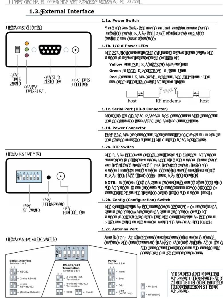
1.3.
External Interface
1.1a. Power Switch
Figure 1.1. Front View Move the Power Switch to the on (up) position to power the Interface Board. DIP Switch [1.2a] settings are only read during a power-up sequence.
1.1d. Power Connector 1.1c. DB‐9 Serial Port 1.1b. I/O & Power LEDs 1.1a. Power Switch
1.1b. I/O & Power LEDs
The LED indicators visualize diagnostic status information. The modem’s status is represented as follows:
Yellow (top LED) = Serial Data Out (to host) Green (middle) = Serial Data In (from host)
Red (bottom) = Power/TX Indicator (Red light is on when powered, off briefly during RF transmission)
1.1c. Serial Port (DB-9 Connector)
Standard female DB-9 (RS-232) DCE connector – This connector can be also used for RS-485 and RS-422 connections.
1.1d. Power Connector
7-18 VDC Power Connector (Center positive, 5.5/2.1mm) – Power can also be supplied through Pin 9 of the DB-9 Serial Port. 1.2a. DIP Switch
Figure 1.2. Back View The DIP Switch automatically configures the XStream RF Modem
to operate in different modes. Each time the modem is powered-on, intelligence inside the XIB-R interface board (inside the modem) programs the modem according to the positions of the DIP Switch. [See figure below for DIP Switch settings]
1.2b. Config Switch 1.2c. Antenna Port 1.2a. DIP Switch
NOTE: In cases where AT Commands should not be sent each time the RF Modem is powered-on, the processor must be disabled by populating J7 on the interface board inside the modem [p21]. 1.2b. Config (Configuration) Switch
The Configuration Switch provides an alternate way to enter “AT Command Mode”. To enter “AT Command Mode” at the RF modem’s default baud rate, hold the Configuration Switch down while powering on the modem using the Power Switch [1.1a]. 1.2c. Antenna Port
Figure 1.3. DIP Switch Settings Port is a 50Ω RF signal connector for connecting to an external
antenna. The connector type is RPSMA (Reverse Polarity SMA) female. The connector has threads on the outside of a barrel and a male center conductor.
Refer to table in the “Automatic
DIP Switch Configurations” [p19]
section for more information about
configurations triggered by the
2.
Interfacing
Protocol
The XStream-PKG-R RF Modem supports the following interfacing protocols: • RS-232
• RS-485 (2-wire) Half-Duplex • RS-485 (4-wire) and RS-422
2.1.
RS-232 Operation
2.1.1.
DIP Switch Settings and Pin Signals
Figure 2.1. Figure 2.2.
RS‐232 DIP Switch Settings Pins used on the female RS‐232 (DB‐9) Serial Connector
DIP Switch settings are read and applied
only while powering‐on.
Table 2.1. RS‐232 Signals and their implementations on the XStream RF Modem
(Low‐asserted signals are distinguished by horizontal line over pin name.) DB-9 Pin RS-232
Name
AT Command
Reference* Description Implementation
1 DCD DO3 Data-Carrier-Detect Connected to DSR (pin6)
2 RXD DO Received Data Serial data exiting the RF Modem (to host)
3 TXD DI Transmitted Data Serial data entering into the RF modem (from host)
4 DTR DI3 Data-Terminal-Ready Can enable POWER-DOWN on the RF Modem
5 GND - Ground Signal Ground
6 DSR DO3 Data-Set-Ready Connected to DCD (pin1)
7 CMD / DI2 Request-to-Send enables “Command Mode” on the RF Modem Provides flow control or
8 DO2 Clear-to-Send Provides flow control
9 RI - Ring Indicator Optional power input that is connected internally to the positive lead of the front power connector
* Inside the XStream RF Modem is an XStream OEM RF Module. The names in this column refer to the pin
signals of the embedded RF module. XStream Commands [p24] used to configure pin behaviors are named
XStream
‐
PKG
‐
R™
RS
‐
232/485
RF
Modem
–
Product
Manual
v5.x00
[2006.02.24]
Wiring Diagram: RS-232 DTE Device to a DCE RF Modem
Figure 2.3. RS‐232 DTE (male connector) device wired to an XStream RF Modem (female connector)
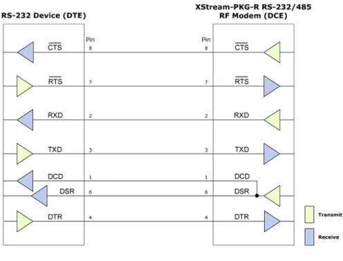
Wiring Diagram: DCE RF Modem to an RS-232 DCE Device
Figure 2.4. XStream RF Modem (female connector) wired to an RS‐232 DTE (male connector) device
Sample Wireless Connection: DTE ÅÆ DCE DCE ÅÆ DCE
2.2.
RS-485 (2-wire) Operation
2.2.1.
DIP Switch Settings and Pin Signals
Figure 2.6. Figure 2.7.
RS‐485 (2‐wire) Half‐Duplex Pins used on the female RS‐232 (DB‐9)
DIP Switch Settings Serial Connector
Figure 2.8.
RS‐485 (2‐wire) with Termination (optional)
Termination is the 120 Ω resistor between T+ and T-.
DIP Switch settings are read and applied only while powering-on.
Note: Refer to Figures 2.15 & 2.16 for RJ-45 connector pin designations used in
RS-485/422 environments.
Table 2.2. RS‐485 (2‐wire half‐duplex) Signals and their implementations on the XStream RF Modem
DB-9 Pin RS-485 Name Description Implementation
2 T/R- (TRA) Negative Data Line Transmit serial data to and from the XStream RF Modem
5 GND Ground Signal Ground
8 T/R+ (TRB) Positive Data Line Transmit serial data to and from the XStream RF Modem 9 PWR Power Optional power input that is connected internally to the front power connector
1, 3, 4, 6, 7 not used
Wiring Diagram: RS-485 (2-wire) Half-Duplex
XStream
‐
PKG
‐
R™
RS
‐
232/485
RF
Modem
–
Product
Manual
v5.x00
[2006.02.24]
2.3.
RS-485 (4-wire) & RS-422 Operation
2.3.1.
DIP Switch Settings and Pin Signals
Figure 2.10. Figure 2.11.
RS‐485 (4‐wire) and RS‐422 Pins used on the female RS‐232 (DB‐9)
DIP Switch Settings Serial Connector
Figure 2.12.
RS‐485 (4‐wire) & RS‐422 with Termination (optional)
Termination is the 120 Ω resistor between T+ and T-.
DIP Switch settings are read and applied only while powering-on.
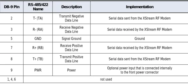
Table 2.3. RS‐485/422 (4‐wire) Signals and their implementations with the XStream‐PKG‐R RF Modem
DB-9 Pin RS-485/422
Name Description Implementation
2 T- (TA) Transmit Negative Data Line Serial data sent from the XStream RF Modem 3 R- (RA) Receive Negative Data Line Serial data received by the XStream RF Modem
5 GND Signal Ground Ground
7 R+ (RB) Receive Positive Data Line Serial data received by the XStream RF Modem 8 T+ (TB) Transmit Positive Data Line Serial data sent from the XStream RF Modem 9 PWR Power Optional power input that is connected internally to the front power connector
1, 4, 6 not used
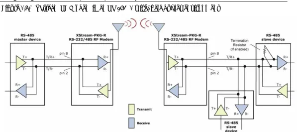
Wiring Diagram: RS-485 (4-wire) Half-Duplex
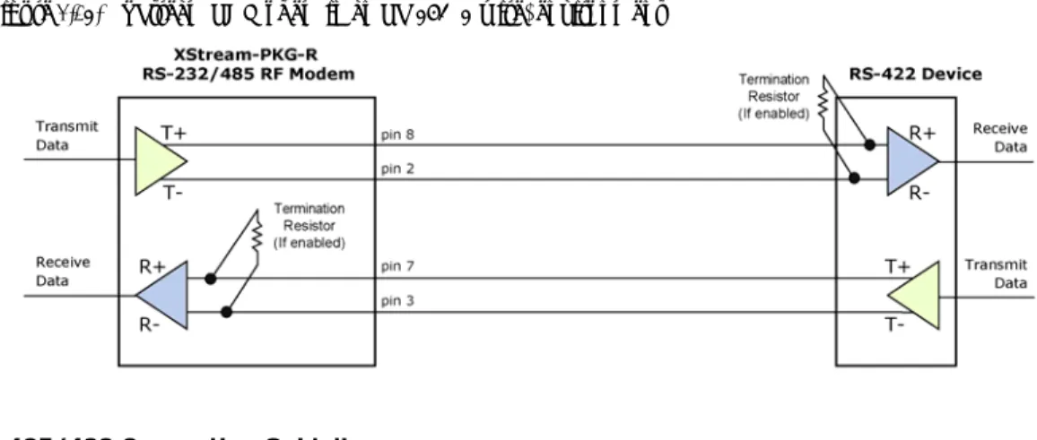
Wiring Diagram: RS-422
Figure 2.14. XStream RF Modem in an RS‐485 (4‐wire) environment
RS-485/422 Connection Guidelines
The RS-485/422 protocol provides a solution for wired communications that can tolerate high noise and push signals over long cable lengths. RS-485/422 signals can communicate as far as 4000 feet (1200 m). RS-232 signals are suitable for cable distances up to 100 feet (30.5 m). RS-485 offers multi-drop capability in which up to 32 nodes can be connected. The RS-422 protocol is used for point-to-point communications.
Suggestions for integrating the XStream Modem with the RS-485/422 protocol: 1. When using Ethernet twisted pair cabling: Select wires so that T+ and T- are connected to
each wire in a twisted pair. Likewise, select wires so that R+ and R- are connected to a twisted pair. (For example, tie the green and white/green wires to T+ and T-.)
2. For straight-through Ethernet cable (not cross-over cable) – The following wiring pattern works well: Pin3 to T+, Pin4 to R+, Pin5 to R-, Pin6 to T-
3. Note that the connecting cable only requires 4 wires (even though there are 8 wires). 4. When using phone cabling (RJ-11) – Pin2 in the cable maps to Pin3 on opposite end of cable
and Pin1 maps to Pin4 respectively.
Figure 2.15. Male (yellow) DB‐9 to RJ‐45 Adapters
Figure 2.16. Female (green) DB‐9 to RJ‐45 Adapters
An RS-232 Accessories Kit is available that includes connectors that facilitate RS-232/485/422 and other serial communications. Refer to the Development Guide in Appendix B for information concerning the connectors and tools included in the kit.
XStream
‐
PKG
‐
R™
RS
‐
232/485
RF
Modem
–
Product
Manual
v5.x00
[2006.02.24]
3.
RF
Modem
Operation
3.1.
Serial Communications
3.1.1.
RS-232 and RS-485/422 Data Flow
Devices that have a UART interface can connect directly through the pins of the XStream Modem as is shown in the figure below.
Figure 3.1. System Data Flow Diagram in a UART‐interfaced environment
(Low‐asserted signals distinguished with horizontal line over signal name.)
3.1.2.
Host and RF Modem I/O Settings
Serial communications between a host and an XStream RF Modem are dependent upon having matching baud rate, parity, stop bit & number of data bits settings. Failure to enter the modem into AT Command Mode is most commonly due to baud rate mismatch. Refer to the table below to ensure host serial port settings match those of the modem.
Table 3.1. Parameter values critical to serial communications between the RF Modem and host
Parameter Setting XStream RF Modem Default Parameter Value
Baud (Serial Data Rate) 9600 bps or 19200 baud (Factory-set RF data rates) Number of Data Bits 8 (NB parameter = 0)
Parity None (NB parameter = 0)
Number of Stop Bits 1 (NB parameter = 0)
Both the XStream RF Modem and host (PC) settings can be viewed and adjusted using
MaxStream’s proprietary X-CTU Software. Use the “PC Settings” tab to configure host settings. Use the “Terminal” or “Modem Configuration” tabs to configure the RF Modem settings. Refer to the RF Modem Configuration sections for more information [p21].
3.1.3.
Flow Control
Figure 3.2. Internal Data Flow Diagram
(The five most commonly‐used pin signals are shown.)
DI (Data In) Buffer and Flow Control
When serial data enters the XStream Modem through the DI Pin, then the data is stored in the DI Buffer until it can be transmitted.
When the RO parameter threshold is satisfied (refer to Transmit Mode [p14] and Command Descriptions [p25] sections for more information), the modem attempts to initialize an RF connection. If the modem is already receiving RF data, the serial data is stored in the modem’s DI Buffer. If the DI buffer becomes full, hardware or software flow control must be implemented in order to prevent overflow (loss of data between the host and XStream RF Modem).
How to eliminate the need for flow control:
1. Send messages that are smaller than the DI buffer size. The size of the DI buffer varies according to the packet size and parity setting used.
2. Interface at a lower baud rate (BD Command) than the fixed RF data rate.
Two cases in which the DI Buffer may become full and possibly overflow:
1. If the serial interface data rate is set higher than the RF data rate of the modem, the modem will receive data from the host faster than it can transmit the data over-the-air.
2. If the modem is receiving a continuous stream of RF data or if the modem is monitoring data on a network, any serial data that arrives on the DI pin is placed in the DI Buffer. The data in the DI buffer will be transmitted over-the-air when the modem no longer detects RF data in the network.
Hardware Flow Control ( ). When the DI buffer is 17 bytes away from being full; by default, the modem de-asserts (high) to signal to the host device to stop sending data [refer to the FT (Flow Control Threshold) and CS (DO2 Configuration) commands]. is re-asserted after the DI Buffer has 34 bytes of memory available.
Software Flow Control (XON). XON/XOFF software flow control can be enabled using the FL (Software Flow Control) Command. This option only works with ASCII data.
DO (Data Out) Buffer and Flow Control
When RF data is received, the data enters the DO buffer and is then sent out the serial port to a host device. Once the DO Buffer reaches capacity, any additional incoming RF data is lost. Two cases in which the DO Buffer may become full and possibly overflow:
1. If the RF data rate is set higher than the interface data rate of the modem, the modem will receive data from the transmitting modem faster than it can send the data to the host. 2. If the host does not allow the modem to transmit data out from the DO buffer because of
being held off by hardware or software flow control.
Hardware Flow Control ( ). If is enabled for flow control (RT Parameter = 2), data will not be sent out the DO Buffer as long as is de-asserted.
Software Flow Control (XOFF). XON/XOFF software flow control can be enabled using the FL (Software Flow Control) Command. This option only works with ASCII data.
XStream
‐
PKG
‐
R™
RS
‐
232/485
RF
Modem
–
Product
Manual
v5.x00
[2006.02.24]
3.2.
Modes of Operation
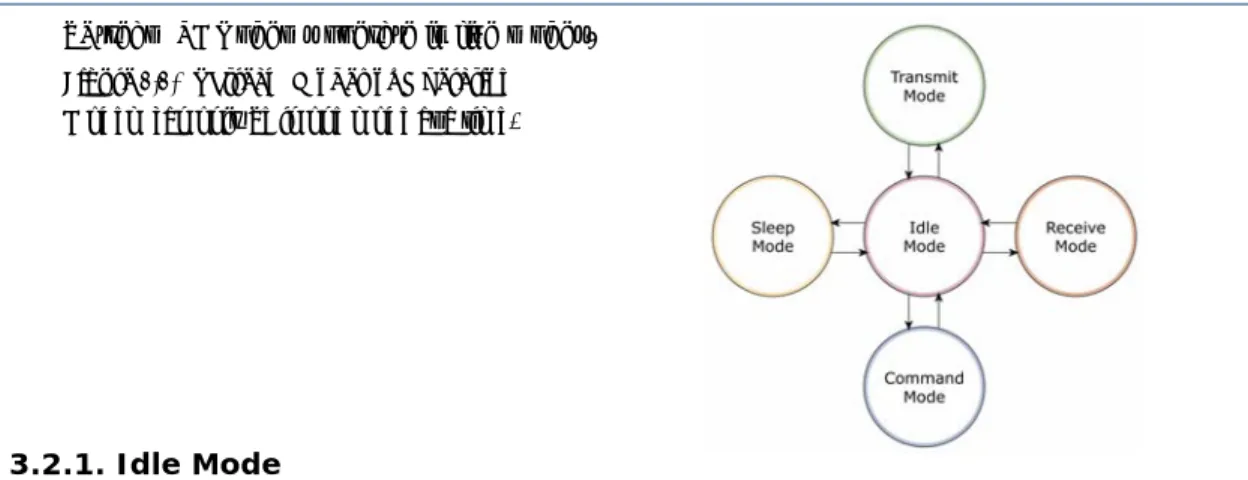
XStream RF Modems operate in five modes.
Figure 3.3. XStream Modes of Operation
Modem can only be in one mode at a time.
3.2.1.
Idle Mode
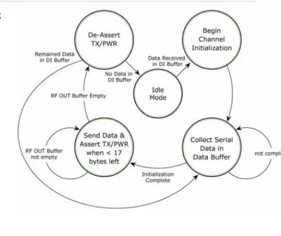
When not receiving or transmitting data, the modem is in Idle Mode. The modem uses the same amount of power in Idle Mode as it does in Receive Mode.
The modem shifts into the other modes of operation under the following conditions: • Serial data is received in the DI Buffer (Transmit Mode)
• Valid RF data is received through the antenna (Receive Mode) • Command Mode Sequence is issued (Command Mode) • Sleep Mode condition is met (Sleep Mode)
After responding to any of the preceding conditions, the modem automatically transitions back into Idle Mode.
3.2.2.
Transmit Mode
When the first byte of serial data is received from the UART in the DI buffer, the modem attempts to shift to Transmit Mode and initiate an RF connection with other modems. After transmission is complete, the modem returns to Idle Mode.
RF transmission begins after either of the following criteria is met:
1. RB bytes have been received in the DI buffer and are pending for RF transmission [refer to RB (Packetization Threshold) command, p34].
The RB parameter may be set to any value between 1 and the RF packet size (PK), inclusive. When RB = 0, the packetization threshold is ignored.
2. At least one character has been received in the DI buffer (pending for RF transmission) and RO time has been observed on the UART [refer to RO (Packetization Timeout) command]. The timeout can be disabled by setting RO to zero. In this case, transmission will begin after RB bytes have been received in the DI buffer.
After either RB or RO conditions are met, the modem then initializes a communications channel. [Channel initialization is the process of sending an RF initializer that synchronizes receiving modems with the transmitting modem. During channel initialization, incoming serial data accumulates in the DI buffer.]
Serial data in the DI buffer is grouped into RF packets [refer to PK (RF Packet Size)]; converted to RF data; then transmitted over-the-air until the DI buffer is empty.
RF data, which includes the payload data, follows the RF initializer. The payload includes up to the maximum packet size (PK Command) bytes. As the transmitting modem nears the end of the transmission, it inspects the DI buffer to see if more data exists to be transmitted. This could be the case if more than PK bytes were originally pending in the DI buffer or if more bytes arrived from the UART after the transmission began. If more data is pending, the transmitting modem assembles a subsequent packet for transmission.
Note: RF reception must complete before the modem is able to enter into Transmit Mode.
RF Data Packet
Figure 3.4. Data Transmission Sequence Æ
The RF packet is the sequence of data used for communicating information between MaxStream
* When streaming multiple RF packets, the RF Initializer is only sent in front of the first packet. RF Initializer
is sent each time a new connection sequence begins. The RF initializer contains
n the
Header
er contains network addressing information that filters incoming RF data. The receiving
CRC (Cyclic Redundancy Check)
uilt-in error checking, a 16-bit CRC (Cyclic Redundancy e Modems. An RF Packet consists of an RF Initializer and RF Data.
Figure 3.5. RF Data Packet Components
An RF initializer
channel information that notifies receiving modems of information such as the hopping pattern used by the transmitting modem. The first transmission always sends an RF initializer. An RF initializer can be of various lengths depending on the amount of time determined to be required to prepare a receiving modem. For example, a wake-up initializer is a type of RF initializer used to wake remote modems from Sleep Mode (Refer to the FH, LH, HT and SM Commands for more information). The length of the wake-up initializer should be longer tha length of time remote modems are in cyclic sleep.
The head
modem checks for a matching Hopping Channel (HP parameter), Vendor Identification Number (ID parameter) and Destination Address (DT parameter). Data that does not pass through all three network filter layers is discarded.
To verify data integrity and provide b
Check) is computed for the transmitted data and attached to the end of each RF packet. On th receiving end, the receiving modem computes the CRC on all incoming RF data. Received data that has an invalid CRC is discarded [Refer to the Receive Mode section, next page].
XStream
‐
PKG
‐
R™
RS
‐
232/485
RF
Modem
–
Product
Manual
v5.x00
[2006.02.24]
3.2.3.
Receive Mode
If the modem detects RF data while in Idle Mode, the modem transitions into Receive Mode to receive RF packets. Once a packet is received, the modem checks the CRC to ensure that the data was transmitted without error. If the CRC data bits on the incoming packet are invalid, the packet is discarded. If the CRC is valid, the packet proceeds to the DO Buffer.
The modem returns to Idle Mode when valid RF data is no longer detected or after an error is detected in the received RF data.
Figure 3.6. Data Reception Sequence
Refer to the Addressing section [p41] of the
RF Communication Modes chapter for more information
regarding address recognition.
3.2.4.
Sleep Modes
Sleep Modes enable the XStream Modem to operate at minimal power consumption when not in
use. Three Sleep Mode options are available:
Note: If serial data exists in the DI buffer while the modem is in Receive Mode, the UART data will be transmitted after the modem is finished receiving the RF data and has returned to Idle Mode.
• Pin Sleep (Host Controlled)
• Serial Port Sleep (Wake on Serial Port activity) • Cyclic Sleep (Wake on RF activity)
For the modem to transition into Sleep Mode, the modem must have a non-zero SM (Sleep Mode) parameter and one of the following must occur:
1. The modem is idle (no data transmission or reception) for a user-defined period of time [Refer to the ST (Time before Sleep) command].
2. SLEEP pin is asserted (only for Pin Sleep option).
In Sleep Mode, the modem will not transmit or receive data until the modem first transitions to Idle Mode. All Sleep Modes are enabled and disabled using SM Command. Transitions into and out of Sleep Modes are triggered by various mechanisms as shown in the table below.
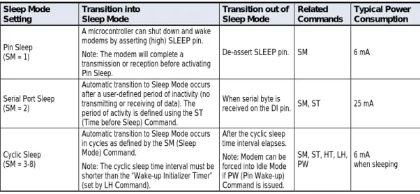
Table 3.2. Summary of Sleep Mode Configurations
Sleep Mode Setting Transition into Sleep Mode Transition out of Sleep Mode Related Commands Typical Power Consumption Pin Sleep (SM = 1)
A microcontroller can shut down and wake modems by asserting (high) SLEEP pin. Note: The modem will complete a transmission or reception before activating Pin Sleep.
De-assert SLEEP pin. SM 6 mA
Serial Port Sleep (SM = 2)
Automatic transition to Sleep Mode occurs after a user-defined period of inactivity (no transmitting or receiving of data). The period of activity is defined using the ST (Time before Sleep) Command.
When serial byte is
received on the DI pin. SM, ST 25 mA
Cyclic Sleep (SM = 3-8)
Automatic transition to Sleep Mode occurs in cycles as defined by the SM (Sleep Mode) Command.
Note: The cyclic sleep time interval must be shorter than the “Wake-up Initializer Timer” (set by LH Command).
After the cyclic sleep time interval elapses. Note: Modem can be forced into Idle Mode if PW (Pin Wake-up) Command is issued.
SM, ST, HT, LH,
PW 6 mA when sleeping
For more information about Sleep Modes, refer to the individual commands listed in “Related Commands”
Pin Sleep (SM = 1)
Pin Sleep requires the least amount of power. In order to achieve this state, the DI3 (SLEEP) pin must be asserted (high). The modem remains in Pin Sleep until the DI3 pin is de-asserted. After enabling Pin Sleep, the SLEEP pin controls whether the XStream Modem is active or in Sleep Mode. When DI3 is de-asserted (low), the modem is fully operational. When DI3 is asserted (high), the modem transitions to Sleep Mode and remains in its lowest power-consuming state until the DI3 (SLEEP) pin is de-asserted. DI3 is only active if the modem is setup to operate in this mode; otherwise the pin is ignored.
Once in Pin Sleep Mode, DO2 ( ) is de-asserted (high), indicating that data should not be sent to the modem. The PWR pin is also de-asserted (low) when the modem is in Pin Sleep Mode.
Note: The modem will complete a transmission or reception before activating Pin Sleep. Serial Port Sleep (SM = 2)
Serial Port Sleep is a Sleep Mode in which the XStream Modem runs in a low power state until serial data is detected on the DI pin.
When Serial Port Sleep is enabled, the modem goes into Sleep Mode after a user-defined period of inactivity (no transmitting or receiving of data). This period of time is determined by ST (Time before Sleep) Command. Once a character is received through the DI pin, the modem returns to Idle Mode and is fully operational.
Cyclic Sleep (SM = 3-8)
Cyclic Sleep is the Sleep Mode in which the XStream Modem enters into a low-power state and awakens periodically to determine if any transmissions are being sent.
When Cyclic Sleep settings are enabled, the XStream Modem goes into Sleep Mode after a user-defined period of inactivity (no transmission or reception on the RF channel). The user-user-defined period is determined by ST (Time before Sleep) Command.
While the modem is in Cyclic Sleep Mode, DO2 ( ) is de-asserted (high) to indicate that data should not be sent to the modem during this time. When the modem awakens to listen for data, DO2 is asserted and any data received on the DI Pin is transmitted. The PWR pin is also de-asserted (low) when the modem is in Cyclic Sleep Mode.
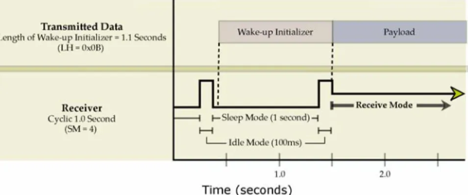
The modem remains in Sleep Mode for a user-defined period of time ranging from 0.5 seconds to 16 seconds (SM Parameters 3 through 8). After this interval of time, the modem returns to Idle Mode and listens for a valid data packet for 100 ms. If the modem does not detect valid data (on any frequency), the modem returns to Sleep Mode. If valid data is detected, the modem
transitions into Receive Mode and receives incoming RF packets. The modem then returns to Sleep Mode after a Period of inactivity that is determined by ST “Time before Sleep” Command. The modem can also be configured to wake from cyclic sleep when SLEEP/DI3 is de-asserted (low). To configure a modem to operate in this manner, PW (Pin Wake-up) Command must be issued. Once DI3 is de-asserted, the modem is forced into Idle Mode and can begin transmitting or receiving data. It remains active until no data is detected for the period of time specified by the ST Command, at which point it resumes its low-power cyclic state.
Note: The cyclic interval time defined by SM (Sleep Mode) Command must be shorter than the interval time defined by LH (Wake-up Initializer Timer).
For example: If SM=4 (Cyclic 1.0 second sleep), the LH Parameter should equal 0x0B (“1.1” seconds). With these parameters set, there is no risk of the receiving modem being asleep for the duration of wake-up initializer transmission. “Cyclic Scanning” explains in further detail the relationship between “Cyclic Sleep” and “Wake-up Initializer Timer”
XStream
‐
PKG
‐
R™
RS
‐
232/485
RF
Modem
–
Product
Manual
v5.x00
[2006.02.24]
Cyclic Scanning. Each RF transmission consists of an RF Initializer and payload. The wake-up initializer contains initialization information and all receiving modems must wake during the wake-up initializer portion of data transmission in order to be synchronized with the transmitting modem and receive the data.
Figure 3.7. Correct Configuration (LH > SM)
Length of the wake‐up initializer exceeds the time interval of Cyclic Sleep. The receiver is guaranteed to detect
the wake‐up initializer and receive the accompanying payload data.
Figure 3.8. Incorrect Configuration (LH < SM)
Length of wake‐up initializer is shorter than the time interval of Cyclic Sleep. This configuration is vulnerable
to the receiver waking and missing the wake‐up initializer (and therefore also the accompanying payload data).
3.2.5.
Command Mode
To modify or read modem parameters, the modem must first enter into Command Mode, the state in which incoming characters are interpreted as commands. Two command types are available for programming the modem:
• AT Commands • Binary Commands
For modified parameter values to persist in the modem registry, changes must be saved to non-volatile memory using WR (Write) Command. Otherwise, parameters are restored to previously saved values when the modem is powered off and then on again.
AT Commands
To Enter AT Command Mode:
1. Send the 3-character command sequence “+++” and observe guard times before and after the command characters. [Refer to the “Default AT Command Mode Sequence” below.] The “Terminal” tab (or other serial communications software) of the X-CTU Software can be used to enter the sequence.
[OR]
2. Assert (low) the pin and turn the power going to the modem off and back on. This result can be achieved by keeping the configuration switch pressed while turning off, then on again the power supplying the RF Modem)
Default AT Command Mode Sequence (for transition to Command Mode):
• No characters sent for one second [refer to the BT (Guard Time Before) Command] • Input three plus characters (“+++”) within one second [refer to the CC (Command
Sequence Character) Command.]
• No characters sent for one second [refer to the AT (Guard Time After) Command.] To Send AT Commands:
Send AT commands and parameters using the syntax shown below:
Figure 3.9. Syntax for sending AT Commands
NOTE: To read a parameter value stored in a register, leave the parameter field blank.
The preceding example would change the modem Destination Address to “1F”. To store the new value to non-volatile (long term) memory, the Write (ATWR) Command must follow.
System Response. When a command is sent to the modem, the modem will parse and execute the command. Upon successful execution of a command, the modem returns an “OK” message. If execution of a command results in an error, the modem returns an “ERROR” message.
To Exit AT Command Mode:
1. Send ATCN (Exit Command Mode) Command. [OR]
2. If no valid AT Commands are received within the time specified by CT (Command Mode Timeout) Command, the Modem automatically returns to Idle Mode.
For examples that illustrate the steps of programming the modem using AT Commands, refer to the RF Modem Configuration [p21] chapter.
XStream
‐
PKG
‐
R™
RS
‐
232/485
RF
Modem
–
Product
Manual
v5.x00
[2006.02.24]
Binary Commands
Sending and receiving parameter values using binary commands is the fastest way to change operating parameters of the XStream RF Modem. Binary commands are used most often to sample signal strength (RS parameter) and/or error counts; or change modem addresses and channels for polling data systems. Since the sending and receiving of register values takes place through the same serial data path as 'live' data (received RF payload), interference between the two types of data can be a concern.
Common questions about using binary commands:
• What are the implications of asserting CMD while live data is being sent or received? • After sending serial data, is there a minimum time delay before CMD can be asserted? • Is a delay required after CMD is de-asserted before payload data can be sent? • How does one discern between live data and data received in response to a command? The CMD pin must be asserted in order to send binary commands to the RF modem. The CMD pin can be asserted to recognize binary commands anytime during the transmission or reception of data. The status of the CMD signal is only checked at the end of the stop bit as the byte is shifted into the serial port. The application does not allow control over when data is received, except by waiting for dead time between bursts of communication.
If the command is sent in the middle of a stream of payload data to be transmitted, the command will essentially be executed in the order it is received. If the radio is continuously receiving data, the radio will wait for a break in the received data before executing the command. The signal will frame the response coming from the binary command request [Figure 3.10]. A minimum time delay of 100 µs (after the stop bit of the command byte has been sent) must be observed before the CMD pin can be de-asserted. The command executes after all parameters associated with the command have been sent. If all parameters are not received within 0.5 seconds, the modem returns to Idle Mode.
Note: When parameters are sent, they are two bytes long with the least significant byte sent first. Binary commands that return one parameter byte must be written with two parameter bytes. Refer to p23 for a binary programming example.
Commands can be queried for their current value by sending the command logically ORed (bit-wise) with the value 0x80 (hexadecimal) with CMD asserted. When the binary value is sent (with no parameters), the current value of the command parameter is sent back through the DO pin.
Figure 3.10.Binary Command Write then Read
Signal #4 is CMD
Signal #1 is the DIN signal to the radio
Signal #2 is the DOUT signal from the radio
Signal #3 is
In this graph, a value was written to a register and then read out to verify it. While not in the middle of other received data, note that the (DO2 pin) signal outlines the data response out of the modem.
IMPORTANT: For the XStream Modem to recognize a binary command, the RT (DI2
Configuration) parameter must be set to one. If binary programming is not
enabled (RT ≠ 1), the modem will not recognize that the CMD pin is asserted and
therefore will not recognize the data as binary commands.
4.
RF
Modem
Configuration
4.1.
Automatic DIP Switch Configurations
Each time the RF Modem is powered-on, intelligence on the XIB-R Interface Board (RS-232/485 interfacing board located inside the RF Modem) sends AT Commands that program the RF Modem based on positions of the DIP Switch. Automatic configurations that take place during the power-on sequence affect stored RF Modem parameter values as shown in the tables below.
Figure 4.1. RF Modem DIP Switch
Table 4.1. RF Modem Power‐up Options (J7 jumper and Config Switch)
Condition Behavior
If J7 is populated Processor is disabled and AT Commands are not sent to the RF Modem If Config Switch is pressed Processor is disabled and RF Modem enters into AT Command Mode If J7 is NOT populated and Config Switch
is NOT pressed Execute logic as shown in table below.
Table 4.2. AT Commands Sent as result of DIP Switch Settings (SW = DIP Switch)
Condition Behavior
Restore Default Parameter Values of the RF Modem
If SW1 & SW2 are ON (up) AT Commands sent: ATRE (Restore Defaults) Command ATWR (Write) Command Serial Interfacing Options
If SW1 is ON (up) AT Commands sent: ATCS 0 (RS-232 Operation: CTS function for CTS line, DB-9 pin 8) ATCD 2 (DO3 - RX LED = low)
If SW1 is OFF (down) AT Commands sent: ATCS 3 (RS-485 or RS-422 Operation) ATCD 2 (DO3 - RX LED = low) Parity Options
If SW5 & SW6 are OFF (down) AT Commands sent: ATNB 0 (parity = none) If SW5 is OFF (down) & SW6 is ON (up) AT Commands sent: ATNB 1 (parity = even) If SW5 is ON (up) & SW6 is OFF (down) AT Commands sent: ATNB 2 (parity = odd)
If SW5 is ON (up) & SW6 is ON (up) AT Commands sent: ATNB 5 (parity = 9th bit data over-the-air, v4.30 only) Exit AT Command Mode
Always AT Commands sent: ATCN (Exit AT Command Mode)
IMPORTANT: To avoid overwriting previously stored custom configurations (due to the automatic configurations that take place each time the RF Modem is powered-on), it is necessary to disable a processor located on the XIB-R interface board. To disable the processor, populate the J7 jumper of the XIB-R Interface Board. By default, J7 is not populated.
XStream
‐
PKG
‐
R™
RS
‐
232/485
RF
Modem
–
Product
Manual
v5.x00
[2006.02.24]
4.2.
Programming Examples
For information about entering and exiting AT and Binary Command Modes, refer to the Command Mode section [p19].
4.2.1.
AT Commands
MaxStream has provided X-CTU software for programming the modem using an extensive list of AT Commands. The X-CTU software provides an interface that is divided into four tabs that facilitate the following functions:
• PC Settings tab - Setup PC serial port to interface with an XStream RF Modem • Range Test tab – Test XStream RF Modem's range in varying environments
• Terminal tab – Configure and read XStream RF Modem parameters using AT Commands • Modem Configuration tab – Configure and read RF Modem parameters
To install the X-CTU Software:
Double-click the “setup_X-CTU.exe” file located in the MaxStream CD or under the “Downloads” section of the following web page: www.maxstream.net/support/downloads.php. Then follow the prompts of the installation screens.
PC Settings Tab
As stated in the Serial Communications section; in order to communicate data to the RF modem through the PC, baud (serial data rate), data bit, parity and stop bit settings on the PC serial port must match those of the RF modem. The PC Settings tab provides a software user interface that facilitates the modification of PC serial port settings.
PC Setup
1. Set the DIP Switch to RS-232 mode. Switch 1 is ON (up) and the remaining 5 switches are OFF (down).
2. Connect the male DB-9 connector of the PC with the female DB-9 connector of the RF modem using an RS-232 cable.
3. Power the RF modem through the power connector.
4. Launch X-CTU Software and select the PC Settings tab; then select parameter values from the dropdown lists that match the current parameter values of the RF modem. [Refer to Table 3.1 on for more information.]
Figure 4.2. RF Modem Configurations through a Serial Cable
Terminal Tab
A terminal program has been built into the X-CTU software and is located under the Terminal tab. The Terminal tab provides an easy-to-use interface for programming the modem.
Multiple AT Commands. Multiple AT commands can be entered on one line with one carriage return at the end of the line. Each command must be delimited by a comma (spaces in between are optional). The “AT” prefix is only sent before the first command and should not be included with subsequent commands in a line.
System Response. When a command is sent to the modem, the modem will parse and execute the command. Upon successful execution of a command, the modem returns an “OK” message. If execution of a command results in an error, the modem returns an “ERROR” message.
EXAMPLE: Restore RF Modem Defaults using the Terminal tab
The following steps show how to read currently stored modem parameter values; then restore the modem parameters to their factory-default states.
Method 1 (One line per command)
Issue AT Command System Response
+++ OK<CR> (Enter into AT Command Mode) ATHP <Enter> (system shows current channel number) <CR> ATRE <Enter> OK<CR> (Restore modem default parameter values) ATWR <Enter> OK<CR> (Write new values to non-volatile memory) ATCN <Enter> OK<CR> (Exit AT Command Mode)
Method 2 (Multiple commands on one line)
Issue AT Command System Response
+++ OK<CR>
ATRE, WR, CN <Enter> OK<CR>
NOTE: Default parameter values of the RF modem can also be restored by selecting the “Restore Defaults” button located on the Modem Configuration tab [refer to the instructions below]. Modem Configuration tab
The “Modem Configuration” tab of the X-CTU software provides an easy-to-use interface for reading and setting RF modem parameters.
EXAMPLE: Read Parameters & Restore Defaults using the Modem Configuration tab The following steps show how to read currently stored modem parameter values; then restore the modem parameters to their factory-default states.
1. Open the X-CTU program (Start --> Programs --> MaxStream --> X-CTU):
2. Under the “PC Settings” tab, select the PC Serial Com Port from the dropdown list that will be used to connect to the RF Modem.
3. Select a "Baud rate" to match the default RF data rate of the RF Modem. Use default values for all other fields.
4. Select the “Modem Configuration” tab.
5. Select the “Read” button to read currently stored parameter values of the modem. 6. Select the “Restore” button to restore factory-default parameter values.
7. Select the “Write” button to save default values to non-volatile (long-term) memory.
4.2.2.
Binary Commands
Example: Send Binary CommandsExample: Use binary commands to change the XStream Modem’s destination address to 0x1A0D and save the new address to non-volatile memory.
1. RT Command must be set to “1” in AT Command Mode to enable binary programming. 2. Assert CMD (Pin is driven high). (Enter Binary Command Mode)
3. Send Bytes [Parameter bytes must be 2 bytes long]:
00 (Send DT (Destination Address) Command)
0D (Least significant byte of parameter bytes) 1A (Most significant byte of parameter bytes)
08 (Send WR (Write) Command)
4. De-assert CMD (Pin is driven low). (Exit Binary Command Mode)
Note: is high when command is being executed. Hardware flow control must be disabled as
XStream
‐
PKG
‐
R™
RS
‐
232/485
RF
Modem
–
Product
Manual
v5.x00
[2006.02.24]
4.3.
Command Reference Table
Table 4.1. XStream Commands (The RF Modem expects numerical values in hexadecimal. “d” denotes decimal equivalent.)
AT Command
Binary
Command AT Command Name Range Command Category
# Bytes Returned
Factory Default
AM v4.30* 0x3A (58d) Auto-set MY - Networking & Security - -
AT 0x05 (5d) Guard Time After 0x02 – 0xFFFF [x 100 msec] Command Mode Options 2 0x0A (10d) BD v4.2B* 0x15 (21d) Baud Rate Standard baud rates: 0 – 6 (custom rates also supported) Serial Interfacing 2 factory-set RF data rate
BK v4.30* 0x2E (46d) Serial Break Passing 0 – 1 Serial Interfacing 1 0
BO v4.30* 0x30 (48d) Serial Break Timeout 0 - 0xFFFF [x 1 second] Serial Interfacing 2 0
BT 0x04 (4d) Guard Time Before 0 – 0xFFFF [x 100 msec] Command Mode Options 2 0x0A (10d)
CB v4.30* 0x33 (51d) Connection Duration Timeout 0x01 – 0xFFFF [x 100 msec] Networking & Security 2 0x28 (4d sec)
CC 0x13 (19d) Command Sequence Character 0x20 – 0x7F Command Mode Options 1 0x2B (“+”)
CD v4.2B* 0x28 (40d) DO3 Configuration 0 – 4 Serial Interfacing 1 0
CE v4.30* 0x34 (52d) Connection Inactivity Timeout 0 – 0xFFFF [x 10 msec] Networking & Security 2 0x64 (1d sec) CF v4.30* 0x35 (53d) Connection Failure Count 0 – 0xFFFF Networking & Security 2 0
CL v4.30* 0x39 (57d) Last Connection Address [read-only] Diagnostics 2 -
CM v4.30* 0x38 (56d) Connection Message 0 – 1 Networking & Security 1 0
CN 0x09 (9d) Exit AT Command Mode - Command Mode Options - -
CO v4.30* 0x2F (47d) DO3 Timeout 0 - 0xFFFF [x 1 second] Serial Interfacing 2 0x03
CS v4.27D* 0x1F (31d) DO2 Configuration 0 – 4 Serial Interfacing 1 0
CT 0x06 (6d) Command Mode Timeout 0x02 – 0xFFFF [x 100 msec] Command Mode Options 2 0xC8 (200d)
DC v4.30* 0x37 (55d) Disconnect - Networking & Security - -
DR v4.30* 0x2D (45d) DI3 Configuration 0 – 4 Serial Interfacing 1 0
DT 0x00 (0d) Destination Address 0 – 0xFFFF Networking & Security 2 0
E0 0x0A (10d) Echo Off - Command Mode Options - -
E1 0x0B (11d) Echo On - Command Mode Options - -
ER 0x0F (15d) Receive Error Count 0 – 0xFFFF Diagnostics 2 0
FH 0x0D (13d) Force Wake-up Initializer - Sleep (Low Power) - -
FL 0x07 (7d) Software Flow Control 0 – 1 Serial Interfacing 1 0
FT v4.27B* 0x24 (36d) Flow Control Threshold 0 – 0xFF [bytes] Serial Interfacing 2 varies
GD 0x10 (16d) Receive Good Count 0 – 0xFFFF Diagnostics 2 0
HP 0x11 (17d) Hopping Channel 0 – 6 Networking & Security 1 0
HT 0x03 (3d) Time before Wake-up Initializer 0 – 0xFFFF [x 100 msec] Sleep (Low Power) 2 0xFFFF ID v4.2B* 0x27 (39d) Modem VID User-settable: 0x10 - 0x7FFF Read-only: 0x8000 – 0xFFFF Networking & Security 2 - IU v4.30* 0x3B (59d) DI2, DI3 Update Timer 0 - 0xFFFF [x 100 msec] Serial Interfacing 2 0x0A (10d) LH 0x0C (12d) Wake-up Initializer Timer 0 – 0xFF [x 100 msec] Sleep (Low Power) 1 0x01
MD v4.30* 0x32 (50d) RF Mode 0 – 4 Networking & Security 1 0
MK 0x12 (18d) Address Mask 0 – 0xFFFF Networking & Security 2 0xFFFF
MY v4.30* 0x2A (42d) Source Address 0 – 0xFFFF Networking & Security 2 0xFFFF
NB v4.30* 0x23 (35d) Parity 0 – 5 Serial Interfacing 1 0
PC v4.22* 0x1E (30d) Power-up Mode 0 – 1 Command Mode Options 1 0
PK v4.30* 0x29 (41d) RF Packet Size 0 - 0x100 [bytes] Serial Interfacing 2 0x40 (64d)
PW v4.22* 0x1D (29d) Pin Wake-up 0 – 1 Sleep (Low Power) 1 0
RB v4.30* 0x20 (32d) Packetization Threshold 0 - 0x100 [bytes] Serial Interfacing 2 0x01
RE 0x0E (14d) Restore Defaults - (Special) - -
RN v4.22* 0x19 (25d) Delay Slots 0 – 0xFF [slots] Networking & Security 1 0
RO v4.2A* 0x21 (33d) Packetization Timeout 0 – 0xFFFF [x 200 µsec] Serial Interfacing 2 0
RP v4.2A* 0x22 (34d) RSSI PWM Timer 0 - 0x7F [x 100 msec] Diagnostics 1 0
RR v4.22* 0x18 (24d) Retries 0 – 0xFF Networking & Security 1 0
RS v4.22* 0x1C (28d) RSSI 0x06 – 0x36 [read-only] Diagnostics 1 -
RT 0x16 (22d) DI2 Configuration 0 - 2 Serial Interfacing 1 0
RZ v4.30* 0x2C (44d) DI Buffer Size [read-only] Diagnostics - -
SB v4.2B* 0x36 (54d) Stop Bits 0 - 1 Serial Interfacing 1 0
SH v4.27C* 0x25 (37d) Serial Number High 0 – 0xFFFF [read-only] Diagnostics 2 -
SL v4.27C* 0x26 (38d) Serial Number Low 0 – 0xFFFF [read-only] Diagnostics 2 -
SM 0x01 (1d) Sleep Mode 0 – 8 Sleep (Low Power) 1 0
ST 0x02 (2d) Time before Sleep 0x10 – 0xFFFF [x 100 msec] Sleep (Low Power) 2 0x64 (100d)
SY 0x17 (23d) Time before Initialization 0 – 0xFF [x 100 msec] Networking & Security 1 0 (disabled)
TO v4.30* 0x31 (49d) DO2 Timeout 0 - 0xFFFF (x 1 sec) Serial Interfacing 2 0x03
TR v4.22* 0x1B (27d) Transmit Error Count 0 – 0xFFFF Diagnostics 2 0
TT v4.22* 0x1A (26d) Streaming Limit 0 – 0xFFFF [0 = disabled] Networking & Security 2 0xFFFF
VR 0x14 (20d) Firmware Version 0 x 0xFFFF [read-only] Diagnostics 2 -
WR 0x08 (8d) Write - (Special) - -
* Firmware version in which command and parameter options were first supported.
4.4.
Command Descriptions
Commands in this section are listed alphabetically. Command categories are designated between the “< >” symbols that follow each command title. XStream Modems expect numerical values in hexadecimal and those values are designated by a “0x” prefix.
AM (Auto-set MY) Command
<Networking & Security> AM Command is used to automatically set the MY (Source Address) parameter from the factory-set modem serial
number. The address is formed with bits 29, 28 and 13-0 of the serial number (in that order). AT Command: ATAM
Binary Command: 0x3A (58 decimal) Minimum firmware version required: 4.30 AT (Guard Time After) Command
AT Command: ATAT
Binary Command: 0x05 (5 decimal) <Command Mode Options> AT Command is used
to set the time-of-silence that follows the
command sequence character (CC Command). By default, AT Command Mode will activate after one second of silence.
Parameter Range: 0x02 – 0xFFFF
[x 100 milliseconds]
Number of bytes returned: 2
Default Parameter Value: 0x0A (10 decimal) Related Commands: BT (Guard Time Before), CC (Command Sequence Character)
Refer to the AT Commands section [p19] to view the default AT Command Mode sequence.
BD (Interface Data Rate) Command
AT Command: ATBD
Binary Command: 0x15 (21 decimal) <Serial Interfacing> BD Command allows the
user to adjust the UART interface data rate and thus modify the rate at which serial data is sent to the RF modem. The new baud rate does not take effect until the CN command is issued. The RF data rate is unaffected by the BD parameter.
Parameter Range (Standard baud rates): 0 – 6 (Non-standard baud rates): 0x7D – 0xFFFF
Parameter BAUD (bps)
Most applications will require one of the seven standard baud rates; however, non-standard baud rates are also supported.
Note: If the serial data rate is set to exceed the fixed RF data rate of the modem, flow control may need to be implemented in the Flow Control section [p13] of this manual.
Non-standard Interface Data Rates: When parameter values outside the range of standard baud rates are sent, the closest interface data rate represented by the number is stored in the
BD register. For example, a rate of 19200 bps can be set by sending the following command line "ATBD4B00". NOTE: When using MaxStream’s X-CTU Software, non-standard interface data rates can only be set and read using the X-CTU ‘Terminal’ tab. Non-standard rates are not accessible through the ‘Modem Configuration’ tab.
Configuration 0 1200 1 2400 2 4800 3 9600 4 19200 5 38400 6 57600 Number of bytes returned: 2
Default Parameter Value: Set to equal to modem’s factory-set RF data rate. Minimum firmware version required: 4.2B (Custom baud rates not previously supported)
When the BD command is sent with a non-standard interface data rate, the UART will adjust to accommodate the requested interface rate. In most cases, the clock resolution will cause the stored BD parameter to vary from the parameter that was sent (refer to the table below). Reading the BD command (send "ATBD" command without an associated parameter value) will return the value that was actually stored to the BD register.
Table 4.2. Parameter Sent vs. Parameter Stored
BD Parameter Sent (HEX) Interface Data Rate (bps) BD Parameter Stored (HEX)
0 1200 0 4 19,200 4 7 115,200 7 12C 300 12B 1C200 115,200 1B207
XStream
‐
PKG
‐
R™
RS
‐
232/485
RF
Modem
–
Product
Manual
v5.x00
[2006.02.24]
BK (Serial Break Passing) Command
AT Command: ATBK
Binary Command: 0x2E (46 decimal) Parameter Range: 0 – 1
Parameter Configuration
0 disable 1 enable Default Parameter Value: 0
Number of bytes returned: 1
Related Commands: BO (Serial Break Timeout) Minimum Firmware Version Required: 4.30 <Serial Interfacing> Pass a serial break condition
on the DI pin to the DO pin of another modem.
BO (Serial Break Timeout) Command
AT Command: ATBO
Binary Command: 0x30 (48 decimal) Parameter Range: 0 – 0xFFFF [x 1 second] Default Parameter Value: 0
Number of bytes returned: 2
Related Commands: BK (Serial Break Passing) Minimum Firmware Version Required: 4.30 <Serial Interfacing> DO pin will return to default
after no serial break status information is received during the timeout period. Use with BK parameter = 1.
BT (Guard Time Before) Command
AT Command: ATBT
Binary Command: 0x04 (4 decimal) <Command Mode Options> BT Command is
used to set the DI pin silence time that must precede the command sequence character (CC Command) of the AT Command Mode Sequence.
Parameter Range: 2 – 0xFFFF
[x 100 milliseconds]
Default Parameter Value: 0x0A (10 decimal) Number of bytes returned: 2
Related Commands: AT (Guard Time After), CC (Command Sequence Character)
Refer to the AT Commands section [p19] to view the default AT Command Mode sequence.
CB (Connection Duration Timeout) Command
AT Command: ATCB
Binary Command: 0x33 (51 decimal) <Networking & Security> Set/Read the
maximum amount of time an exclusive
connection between a base and remote modem in a point-to-multipoint network is sustained. The remote modem will disconnect when this timeout expires.
Parameter Range: 0x01 – 0xFFFF
[x 100 milliseconds]
Default Parameter Value: 0x28 (4d seconds) Number of bytes returned: 2
Related Commands: CE (Connection Inactivity Timeout), DC (Disconnect), MD (RF Mode) Minimum Firmware Version Required: 4.30 CC (Command Sequence Character) Command
AT Command: ATCC
Binary Command: 0x13 (19 decimal) Parameter Range: 0x20 – 0x7F
Default Parameter Value: 0x2B (ASCII “+” sign) Number of bytes returned: 1
Related Commands: AT (Guard Time After), BT (Guard Time Before)
<Command Mode Options> CC Command is used to set the ASCII character to be used between Guard Times of the AT Command Mode Sequence (BT+ CC + AT). The AT Command Mode Sequence activates AT Command Mode (from Idle Mode).
Refer to the AT Commands section [p19] to view the default AT Command Mode sequence.
CD (DO3 Configuration) Command
AT Command: ATCD
Binary Command: 0x28 (40 decimal) Parameter Range: 0 – 2 Parameter Configuration 0 RX LED 1 Default high 2 Default low 3 (reserved) 4 addressed to modem sent Assert only when packet Default Parameter Value: 0
Number of bytes returned: 1
Minimum Firmware Version Required: 4.2B <Command Mode Options> CD Command is
used to redefine the behavior of the DO3 (Data Output 3)/RX LED line.
CE (Connection Inactivity Timeout) Command
AT Command: ATCE
Binary Command: 0x34 (52 decimal) <Networking & Security> Set/Read the duration
of inactivity that will cause a break in a
connection between modems. The base modem will disconnect when no payload has been transferred for the time specified by the CE parameter.
Parameter Range: 0 – 0xFFFF
[x 10 milliseconds]
Default Parameter Value: 0x64 (1d second) Number of bytes returned: 2
Related Commands: CB ( Connection Duration Timeout), DC (Disconnect), MD (RF Mode) Minimum Firmware Version Required: 4.30 CF (Connection Failure Count) Command
AT Command: ATCF
Binary Command: 0x35 (53 decimal) Parameter Range: 0 – 0xFFFF Default Parameter Value: 0 Number of bytes returned: 2
Minimum Firmware Version Required: 4.30 <Diagnostics> Set/Read the number of times the
base modem expired retries attempting to send a Connection Grant Packet.
Set the parameter value to zero to clear the register.
CL (Last Connection Address) Command
AT Command: ATCL
Binary Command: 0x39 (57 decimal) Parameter Range: 0 – 0xFFFF [read-only] Number of bytes returned: 2
Minimum Firmware Version Required: 4.30 <Diagnostics/Networking & Security> Read the
address of the remote modem that last
connected to the base modem. A remote modem will return its DT (Destination Address)
parameter.
CM (Connection Message) Command
AT Command: ATCM
Binary Command: 0x38 (56 decimal) Parameter Range: 0 – 1
Parameter Configuration
0 enable
1 disable
Default Parameter Value: 0 Number of bytes returned: 1
Minimum Firmware Version Required: 4.30 <Networking & Security> Select whether base
sends connect messages to the host when a connection is established. When enabled, a “CONNECTXXXX” string is sent to the host of the base modem. “XXXX” is the MY (Source Address) of the connected remote modem.