Electronically Tunable Current-Mode Quadrature
Oscillator Using Single MCDTA
Yongan LI
School of Physics and Electronic Engineering, Xianyang Normal University, Xianyang 712000,China [email protected]
Abstract. This paper presents a modified current dif-ferencing transconductance amplifier (MCDTA) and a MCDTA based quadrature oscillator. The oscillator is current-mode and provides current output from high output impedance terminals. The circuit uses only one MCDTA and two grounded capacitors, and is easy to be integrated. Its oscillation frequency can be tuned electronically by tuning bias currents of MCDTA. Finally, frequency error is analyzed. The results of circuit simu-lations are in agreement with theory.
Keywords
Quadrature sinusoidal oscillator, current-mode circuit, low-component count, MCDTA.
1.
Introduction
Recently, current differencing transconductance amplifiers (CDTAs) have been extensively used as building blocks in signal generation applications and current-mode signal processing. The current-mode filters, oscillators, and rectifiers in literature [1] – [16] have well explained this viewpoint. However, the oscillators in [5] – [8] use exces-sive number of passive components, including floating capacitors. Thus, they are not suitable for monolithic in-tegration. The oscillators in [9] – [11] employ two ground-ed capacitors, they are resistor-less and the tuning laws for the oscillation condition and the oscillation frequency are independent. But these circuits use too many active devices, so they are not oscillators with low component count. The oscillators in [12] – [15] are overlarge due to partial utili-zation of the CDTA terminals, and there is an external linear resistor appearing at the z terminal of the first CDTA in Fig. 2(a) of [12] and [13], which is simulated by means of a CDTA in [13] and [14]. This is redundant, since a resistor can be easily simulated by only one OTA, rather than using a CDTA.
In this paper, we present a modified current dif-ferencing transconductance amplifier (MCDTA). The proposed MCDTA element consists of two well-known and mutually independent building blocks, namely Z-Copy
CDTA and OTA. OTA is relatively independent. This is different from CDTA, MO-CDTA, and MCDTA in existing literature. As an application, the MCDTA based quadrature oscillator is given. The circuit uses only one MCDTA and two grounded capacitors, and is easy to be integrated. Its oscillation frequency can be tuned electronically by tuning bias currents of MCDTA. The outputs of the circuit possess high output impedances, and it enjoys low passive sen-sitivities. The results of circuit simulations are in agreement with theory.
2.
Circuit Description
2.1
MCDTA
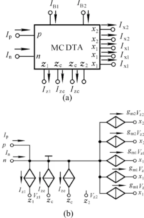
By adding a transconductance amplifier and a current mirror in CDTA, the number of x ports and z ports is ex-tended, and a MCDTA is realized. It is noted that the second stage transconductance amplifier in MCDTA is relatively independent, which is different from the existing MO-CDTA. The new MCDTA circuit representation and equivalent circuit are shown in Fig. 1. Its terminal relationships can be characterized by the following set of equations 1 1 1 1 2 2 2 0, , , , p n z zc p n x m z x m z V V I I I I I g V I g V (1) and T B2 2 T B1 1
2
2
V
I
g
V
I
g
m
Ł
¬
m
(2)where IB1 and IB2 are bias currents of MCDTA, VT is the
thermal voltage and gm is the transconductance gain of
MCDTA.
2.2
Proposed Oscillator
Fig. 2 shows MCDTA-based current-mode quadrature sinusoidal oscillator. From routine analysis of the circuit in Fig. 2, the loops gain of the oscillator is obtained:
1 1 2 1 1 2 ( ) m m m sC g g L s sC g sC .
(a)
(b)
Fig. 1. MCDTA (a) symbol and (b) equivalent circuit.
Fig. 2. MCDTA-based current-mode quadrature sinusoidal oscillator.
The characteristic equation of the oscillator can be written as 1 1 2 1 1 2 1 ( ) 1 m m 0. m sC g g L s sC g sC That is 2 1 2 2 1 1 2 1 2 1 2 0. m m m m g C g C g g s s C C C C (3)
The modified oscillation condition and oscillation frequency can be obtained as
2 1 1 2C g C gm m , (4) 1 2 B1 B2 1 2 T 1 2 1 1 . 2 4 m m o g g I I f C C V C C (5)
From the circuit in Fig. 2, for sinusoidal steady state, the current transfer function from Io1 to Io2 is
2 2 1 1 1 2 . o m o m I g C j j I g C (6)
magnitudes. From (5), if IB1 = IB2 = IB and C1≥C2, fo can
be tuned by adjusting bias current IB (about this question, a
simple solution has been given in the appendix). Therefore, the proposed circuit is an electronically tunable current-mode quadrature sinusoidal oscillator with low component-count.
All the active and passive sensitivities of the oscillator can be expressed as 2 1 2 1, o f C C S , 2 1 2 1, o B B f I I S . (7)
(7) shows that active and passive fo sensitivities are less
than unity in magnitude and hence the circuit exhibits a good sensitivity performance.
2.3
Non-Ideal Analysis
If the parasitic resistances at terminal p and n are negligible (ideally they are zero), then the parasitic imped-ances appearing at the x terminals would be connected between virtual grounds and actual ground and thereby eliminating their effect. Parasitic capacitances appearing at the high output impedance z1 terminal, zc terminal, z2
terminal, and x1 terminal and ground are absorbed into the
external capacitors as they are shunt with them. This feature of grounded capacitor based circuits makes them par-ticularly desirable for monolithic integration. In practice, in the non-ideal case, to alleviate the effects of the parasitic impedances, the parasitic conductances and parasitic capac-itors at terminal z1, zc, z2 and x1 should be
take into account.
Re-analysis of the circuit in Fig. 2 yields the following modified loops gain
1 p1 1 1 2 1 p1 1 1 2 p2 2 ( ) ( ) . ( ) ( ) m m m s C C G g g L s s C C G g s C C G
where G1 denotes parasitic conductance in parallel with C1,
G2 denotes parasitic conductance in parallel with C2, Cp1 and
Cp2 denote parasitic capacitors in parallel with C1 and C2,
respectively.
The modified characteristic equation of the oscillator is
. 0 ) ( ) ( ) ( 1 ) ( 1 2 p2 2 2 1 1 p1 1 1 1 p1 1 G C C s g g G C C s g G C C s s L m m m That is 2 2 1 p1 1 1 2 p2 2 1 p1 2 p2 1 2 2 1 1 2 1 2 1 p1 2 p2 [( )( ) ( )( )] ( )( ) 0. ( )( ) m m m m m m s G g C C G g C C s C C C C G G G g G g g g C C C C (8)
The modified oscillation condition is ) ( ) )( ( ) ( 1 p1 1 1 2 p2 2 1 p1 2C C G g C C G C C gm m . (9)
The modified oscillation frequency is
' 1 2 2 1 1 2 1 2 1 p1 2 p2 1 . 2 ( )( ) m m m m o G G G g G g g g f C C C C (10)
Assuming gm1 = gm2 = gm, ignoring the second-order
infinitesimal G1G2 and Cp1Cp2, and using 1x1x/2,
for |x| << 1, (10) becomes ) 2 2C 2 1 ( 2 p2 1 p1 2 1 ' C C C g G G f f m o o . (11)
(9) shows that if gm1 = gm2 = gm, the modified
oscillation condition changes into
C1 ≥ (C2+Cp2)(G1+gm1)/(gm2-G2)-CP1,
hence, C1 must be slightly greater than C2 due to non-ideal
factors. (11) shows that that if gm1 = gm2 = gm, the modified
oscillation frequency changes into
fo’=fo [1-(G1-G2)/2gm-Cp1/2C1-Cp2/2C2],
therefore, taking into account non-ideal factors, the oscillation frequency becomes smaller.
From (11), the deviation for oscillation frequency is
' p1 p2 1 2 1 2 . 2 2C 2 o o o m C C f f G G f g C (12)
The sensitivity study of the modified oscillation frequency indicates that
' 1 p1 1 1 , 2(1 / ) o f C S C C ' 2 p2 2 1 , 2(1 / ) o f C S C C ' p1 C 1 p1 1 , 2(1 / ) o f S C C ' p 2 C 2 p 2 1 , 2(1 / ) o f S C C ' ' 2 2 1 2 1 2 2 1 1 2 1 2 , 2( ) o o m B f f m g I m m m m G g S S G G G g G g g g ' ' 1 1 1 2 1 2 2 1 1 2 1 2 , 2( ) o o m B f f m m g I m m m m g g S S G G G g G g g g ' 1 1 2 2 1 2 2 1 1 2 1 2 ( ) , 2( ) o f m G m m m m G G g S G G G g G g g g ' 2 2 1 1 1 2 2 1 1 2 1 2 ( ) . 2( ) o f m G m m m m G G g S G G G g G g g g (13)
From the above expressions, it is seen that all passive and active sensitivities of the circuit are low.
3.
Simulation Results
In order to test the performances of the proposed circuit, the MO-CCCDTA of literature [17] is modified to MCDTA of Fig. 3, and the sub-circuit for MCDTA is created on transistor QNL(BF = 100) and QPL(BF = 100) by ELECTRONICS WORKBENCH 5.0 software (EWB 5.0), then Fig. 2 is created. Finally, the Fig. 2 circuit is simulated with ± 1.5 V power supplies, C1 = 1.08 nF,
C2= 1 nF, IB1 = IB2 = IB=25 A, and IB3 = 1000 A, which
yields parasitic resistor Rp = Rn= VT/2IB3 = 13 , hence,
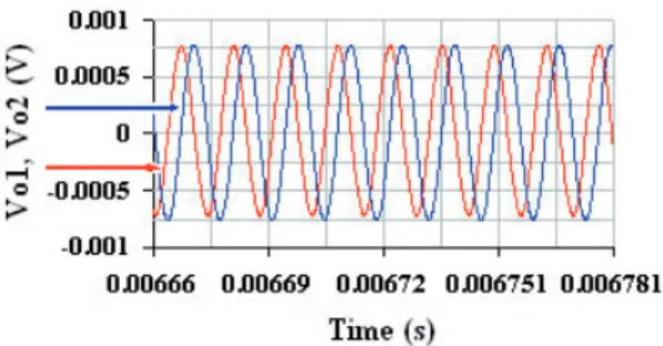
terminals p and n are at virtual ground. The simulation results are shown in Fig. 4. This shows that the circuit really created a quadrature sinusoidal oscillation. Using (5) yields the design value for oscillation frequency fo = 73.6657 kHz; using the pointer in EWB5.0 yields the
actual value for oscillation frequency fo’ = 72.1671 kHz, so
the deviation for oscillation frequency is (72.1671 – 73.6657) / 73.6657 = -2.03 %.
To illustrate the controllability of the oscillation frequency by adjusting IB, let C1 = C2 = 1 nF, IB1 =
IB2 = IB = 50 A, IB3 = 1000 A. Simulation result of the
Fig.4. The steady-state waveforms for proposed circuit when C1 = 1.08 nF, C2 = 1 nF, IB = 25 A, RL=100 .
Fig.5. The steady-state waveforms for proposed circuit when C1 = C2 = 1 nF, IB = 50 A, RL = 100 .
Fig. 6. Simulation result of the output spectrum when C1 = 1.08 nF, C2 = 1 nF, IB = 25 A, RL = 100 .
quadrature outputs is shown in Fig. 5. Theoretically, for the ideal case, the design value for oscillation frequency is 153.111 kHz. Using the pointer in EWB 5.0, it has been observed that the actual value for oscillation frequency is 143.950 kHz, so the deviation for oscillation frequency is (143.95 – 153.111) / 153.111= -5.98 %. The error is mainly due to parasitic impedances appearing in z, g, and x ter-minals. From Fig. 3, we can obtain G1 = Gz+ Gg+ Gx,
G2 = Gz+ Gg, of them, Gz denotes output conductance of
current differencing circuit of MCDTA, Gg denotes input
conductance of the tranconductance amplifier of MCDTA, Gx denotes output conductance of output current mirror of
MCDTA. Using the frequency analysis in EWB 5.0, we receive G1 = 0.0426 ms, G2 = 0.0416 ms, and the
corresponding parasitic capacitance Cp1 = 0.0644 nF,
Cp2 = 0.056 nF. Substituting these data into (12) gives that
the relative error is -6.1 %. It is noted that the results of circuit simulations are in agreement with theory.
Fig. 6 shows the simulated output spectrum, where the total harmonic distortion is about 3.16562 %. The dis-tortion is due to the fact that the nonlinear elements (such
exponentially in amplitude until the linear dynamic range of two OTAs in MCDTA is exceeded. When two OTAs approach their saturation regions, respectively, the oscil-lator can sustain an output signal with small distortion.
4.
Conclusions
In this paper
,
a new MCDTA is presented. It has two parameters controlled electronically, the IB1 and IB2.A MCDTA-based current-mode quadrature sinusoidal os-cillator with high output impedance was realized. It uses relatively few components and grounded capacitors. Its oscillation frequency can be tuned by varying the bias current of MCDTA. Although the oscillation condition for proposed oscillator cannot be adjusted electronically, this topology can be introduced as an economical oscillator. The proposed circuit structure is expected to be useful for applications in communications, instrumentation and meas-urement systems, especially at a high frequency range.
Appendix
There is a mechanism by which IB1 and IB2 can be
varied together. Fig. 7 shows a simple implementation. This is a multi-transistor current mirror. The relationship between each load current and the reference current, as-suming all transistors are matched and Early voltage VA = ∞, is C EE BE B1 B2 R . V V V I I I R
It is apparent that if the circuit parameters R, VEE, and
VBE are given, the load currents IB1 and IB2 can be varied
simultaneously by varying an external control voltage VC.
Fig. 7. Multi-transistor current mirror.
Acknowledgements
This work is supported by the Natural Science Foundation of the Education Bureau of Shaanxi Province, China (Grant No. 2010JK889). The author would also like to thank the anonymous reviewers for their suggestions.
References
[1] BIOLEK, D., SENANI, R., BIOLKOVA, V., KOLKA, Z. Active elements for analog signal processing: classification, review, and new proposals. Radioengineeing, 2008, vol. 17, no. 4, p. 15 – 32. [2] KESKIN, A. U., BIOLEK, D., HANCIOGLU, E., BIOLKOVA, V.
Current-mode KHN filter employing current differencing trans-conductance amplifier. AEU – International Journal of Electronics and Communications, 2006, vol. 60, no. 6, p. 443 – 446.
[3] LI, Y. Forth order current mode band pass filter with coupled tuned by current using CCCDTAs. Journal of Electron Devices, 2010, vol. 7, p. 210 – 213.
[4] LAHIRI, A., CHOWDHURY, A. A novel first-order current-mode all-pass filter using CDTA. Radioengineeing, 2009, vol. 18, no. 3, p. 300 – 305.
[5] JAIKLA, W., SIRIPRUCHYANUN, M., BAJER, J., BIOLEK, D. A simple current-mode quadrature oscillator using single CDTA. Radioengineering, 2008, vol. 17, no. 4, p. 33 – 40.
[6] KESKIN, A. U., BIOLEK, D. Current mode quadrature oscillator using current differencing transconductance amplifiers (CDTA). IEE Proc.-Circuits Devices System, 2006, vol. 153, no. 3, p. 214 – 218.
[7] LAHIRI, A. Explicit-current-output quadrature oscillator using sec-ond-generation current conveyor transconductance amplifier. Radioengineeing, 2009, vol. 18, no. 4, p. 522 – 526.
[8] LAHIRI, A. Novel voltage/current-mode quadrature oscillator using current differencing transconductance amplifier. Analog Integrated Circuits and Signal Processing, 2009, Doi: 10.1007/s10470-009- 9291-0.
[9] LAHIRI, A. Resistor-less mixed-mode quadrature sinusoidal oscil-lator. International Journal of Computer and Electrical En-gineering, 2010, vol. 2, no. 1, p.63 – 66.
[10] LAHIRI, A. New current-mode quadrature oscillators using CDTA. IEICE Electronics Express, 2009, vol. 6, no. 3, p. 135 – 140.
[11] TANGSRIRAT, W., TANJAROEN, W. Current-mode sinusoidal quadrature oscillator with independent control of oscillation frequency and condition using CDTAs. Indian Journal of Pure & Applied Physics, 2010, vol. 48, no. 5, p. 363 – 366.
[12] SIRIPRUCHYANUN, M, JAIKLA, W., CMOS current-controlled current differencing transconductance amplifier and applications to analog signal processing. AEU-International Journal of Electronics and Communications, 2008, vol. 62, no. 4, p. 277 – 287.
[13] PRASAD, D., BHASKAR, D, R., SINGH, A, K. Realisation of Single-Resistance-Controlled Sinusoidal Oscillator: A new ap-plication of the CDTA. WSEAS Transactions on Electronics, 2008, vol. 5, no. 6, p. 257 – 259.
[14] TANGSRIRAT, W. Current differencing transconductance amplifier-based current-mode four-phase quadrature oscillator. Indian Journal of Engineering and Materials Sciences, 2007, vol. 14, no. 7, p. 289 – 294.
[15] TANGSRIRAT, W., TANJAROEN, W. Current-mode multiphase sinusoidal oscillator using current differencing transconductance amplifiers. Circuits, Systems and Signal Process, 2008, vol. 27, no. 1, p. 81 – 93.
[16] BIOLEK, D., HANCIOGLU, E., KESKIN, A, Ü.
High-performance current differencing transconductance amplifier and its application in precision current-mode rectification AEU-International Journal of Electronics and Communication, 2008,vol 62, no. 2, p. 92 – 96.
[17] DUANGMALAI D, MANGKALAKEEREE S,
SIRIPRU-CHYANUN M. High output-impedance current-mode quadrature oscillator using single MO-CCCDTA. In The seventh PSU Engineering Conference. Songkla (Thailand), 2009, p. 287 – 290.
About Author ...
Yongan LI is currently a professor at the School of Physics and Electronic Engineering, Xianyang Normal University, Xianyang. 712000, China.