DMA-Aware Memory Energy Management
∗
Vivek Pandey, Weihang Jiang, Yuanyuan Zhou, and Ricardo Bianchini† Department of Computer Science,University of Illinois at Urbana Champaign {pandey1,wjiang3,yyzhou}@cs.uiuc.edu
†Department of Computer Science Rutgers University [email protected]
Abstract
As increasingly larger memories are used to bridge the widening gap between processor and disk speeds, main mem-ory energy consumption is becoming increasingly dominant. Even though much prior research has been conducted on memory energy management, no study has focused on data servers, where main memory is predominantly accessed by DMAs instead of processors.
In this paper, we study DMA-aware techniques for mem-ory energy management in data servers. We first character-ize the effect of DMA accesses on memory energy and show that, due to the mismatch between memory and I/O bus band-widths, significant energy is wasted when memory is idle but still active during DMA transfers. To reduce this waste, we propose two novel performance-directed energy management techniques that maximize the utilization of memory devices by increasing the level of concurrency between multiple DMA transfers from different I/O buses to the same memory device. We evaluate our techniques using a detailed trace-driven simulator, and storage and database server traces. The results show that our techniques can effectively minimize the amount of idle energy waste during DMA transfers and, consequently, conserve up to 38.6% more memory energy than previous ap-proaches while providing similar performance.
1
Introduction
As shown in many previous studies [16, 17, 18], main memory is one of the largest energy consumers in high-end servers, such as data servers (including file, storage, and database servers) in data centers. Measurements from real server systems show that memory can consume 50% more power than processors [17]. In fact, memory energy consump-tion will become increasingly dominant as increasingly larger memories are used to bridge the widening gap between pro-cessor and disk speeds. For example, the most recent EMC Symmetrix DMX3000 storage system can be configured to
∗This research has been supported by NSF CAREER Awards
CNS-0347854 and CCR-0238182, NSF CCR-03-12286, NSF EIA 02-24453, IBM SUR grant, and IBM Faculty award.
have up to 256 GB of main memory [8], and the IBM eSeries p5 595 server (the one that provides the best TPC-C perfor-mance in the world) is configured with 2 TB of main mem-ory [13] to avoid accessing disks. As a result, memmem-ory energy consumption will soon become dominant in data servers.
Even though much research has been conducted on mem-ory energy management [1, 6, 15, 16, 18, 25], most of the previous works studied only computation-centric applications, such as SPEC benchmarks or multimedia applications. To the best of our knowledge, no prior studies have considered the memory accesses generated by network and disk DMAs, which are the dominant accesses in data servers.
The memory accesses made by DMAs are different from those made by processors and therefore have different impli-cations for memory energy management. Most DMA trans-fers usually have large size such as multiple data blocks of size 512 bytes (disk sector size) or 8 KBytes (page size), whereas each memory access from processors involves a single cache line. As a result, a DMA transfer requires the accessed mem-ory device to be in active mode for a relatively long period of time, as compared to processor-generated accesses. Con-sequently, the memory energy consumption due to DMA ac-cesses is less sensitive to the length of idleness thresholds and the energy and time overheads of power mode transitions, which have been the main topics of previous research on mem-ory energy management. The energy wasted waiting and then transitioning power modes is only a small fraction of the total memory energy consumption, as shown in Figure 2(b).
In contrast, DMA accesses have a different type of energy waste as each DMA operation is broken into a large number of small memory accesses, which are referred to in this paper as DMA-memory requests for simplicity. Due to the mismatch between I/O bus and memory transfer rates, DMA-memory re-quests cannot arrive at the memory device at the rate at which a modern memory device can serve them. Further, the time gap between any two DMA-memory requests is too short to justify transitioning the memory device into low-power mode to con-serve energy. As a result, energy is wasted when the memory device stays in high-power mode waiting between every two DMA-memory requests during a large DMA transfer.
To address this problem, we conduct the first study of DMA-aware memory energy management. More
specifi-Processors cache
Main memory buffer cache Meta-data Read request Network DMAs Disk DMAs Clients 1 2 3 4 5 accesses by processors small DMA transfer large DMA transfer
6
Figure 1. Path of a read request in a typical stor-age server.
cally, we first characterize the effect of DMA accesses on memory energy consumption. To minimize memory en-ergy waste caused by DMA accesses, we propose two novel performance-directed DMA-aware memory energy manage-ment techniques. Both techniques strive to maximize the uti-lization of the memory active energy. The first technique does this by temporally aligning DMA operations from different I/O buses to the same memory device to sequence these op-erations in lockstep, whereas the second technique lays pages out in memory according to the logarithmic page popularity curve commonly found in data server workloads to increase the opportunity to temporally align DMA transfers.
We evaluate our techniques using a detailed trace-driven simulator, and both synthetic traces and real traces collected from a commercial database server (IBM DB2) and a real storage server. The results show that our techniques can ef-fectively minimize the amount of idle energy waste during DMA transfers and, consequently, conserve up to 38.6% more energy than previous techniques while still providing similar performance. Our results also show the effect of workload and hardware characteristics on memory energy conservation.
The rest of the paper is organized as follows. Section 2 briefly describes the background behind the paper. Section 3 discusses the effect of DMA transfers on memory energy con-sumption. Section 4 describes our two techniques for DMA-aware memory energy management. Section 5 presents our evaluation methodology and simulation results. Section 6 dis-cusses the difference between our techniques and prior related work. Section 7 concludes the paper.
2
Background
In this section, we detail the path of different types of re-quests in data servers, as well as the memory power model and power management mechanisms we assume.
2.1
Access Path in a Data Server
Figure 1 shows the path of a read request for an 8-Kbyte data block in a typical data server, using a storage server as an example. When a read request arrives from the storage area network (SAN), the processor first parses the request and checks the index table of the main-memory buffer cache to see
Power State/Transition Power Time
Active 300mW
-Standby 180mW
-Nap 30mW
-Powerdown 3mW
-Active→Standby 240mW 1 memory cycle
Active→nap 160mW 8 memory cycle
Active→powerdown 15mW 8 memory cycle
Standby→Active 240mW +6ns
Nap→Active 160mW +60ns
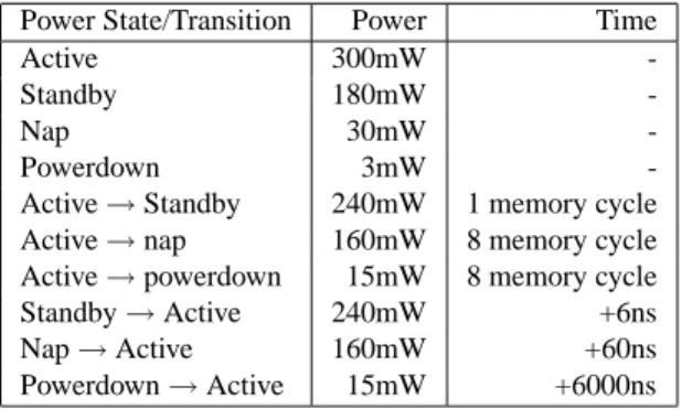
Powerdown→Active 15mW +6000ns Table 1. Power consumption and transition time for different power modes.
if the requested block is currently cached. If it is, the proces-sor initiates a network DMA operation to transfer the data out directly from main memory to the SAN. If it is not, the pro-cessor initiates a disk DMA operation to read the data from disk to the main-memory buffer cache and then initiates a net-work DMA operation to send the data out. The path of a write request is similar but data flows in the reverse direction.
For every request, the main memory needs to service one or two large DMA data transfers of 8 Kbytes. In many cases, es-pecially in storage servers, processors only access meta-data, such as index tables and requests, and does little processing of the actual data. Since the meta-data is usually orders of mag-nitude smaller than the actual data and can be placed in a sepa-rate memory device managed using previous dynamic energy management strategies, our work does not consider memory accesses to meta-data.
Interestingly, in database servers, data in the buffer cache are accessed by the processor as well as the DMA engines. However, the granularity of accesses by the DMA engines is significantly larger than that by processors. As previous memory energy management strategies [16, 18] can handle accesses by processors, our discussion will focus on memory energy management for DMA operations, even though we still discuss the coordination with processor-initiated accesses and evaluate our ideas using traces that contain accesses by both processors and DMAs.
2.2
Memory Power Model and Management
The power model we assume for the memory subsystem is based on memory chips capable of operating in multiple power modes. In particular, our model follows the specifica-tions for Rambus DRAM (RDRAM) [22]. In RDRAM, each memory chip can be independently set to an appropriate power state: active, standby, nap, or powerdown. In active state, all parts of the chip are active, whereas each low-power mode only activates certain parts of the memory circuitry [22]. Data is preserved in all power modes. More details about the work-ings of these modes can be found elsewhere [22, 23].
An RDRAM chip must be in active mode to perform a read or write operation. Accesses to chips in low-power
operat-ing modes incur additional delay and energy for broperat-ingoperat-ing the chip back to active state. The delay varies from several cycles to several thousand cycles, depending on which low-power state the chip is in. Table 1 lists the power states, their power consumptions, as well as their transition costs back to active mode. These numbers are the same as those in [18], which were obtained from the latest RDRAM specifications [22].
Previous research on memory energy management [16, 18] has explored when to send memory devices to which low-power modes. These techniques can be divided into two classes: static and dynamic. Static techniques always put a device in a fixed low-power mode. The device only transitions back into full-power mode if it needs to service a request. Af-ter a request is serviced, it immediately transitions back to the original mode, unless there is another request waiting. In con-trast, dynamic techniques transition a device from the current power mode to the next lower power mode, after being idle for a specified threshold amount of time (different thresholds are used for different power modes). The threshold is usually set based on the break-even time [16] or dynamically adjusted based on the memory accesses from processors.
As previous studies [16, 18] show that dynamic schemes can conserve more energy than static schemes, our study fo-cuses on dynamic management in our evaluation, even though our DMA-aware memory energy management techniques can be applied to both static and dynamic management.
3
Energy Implications of DMA Transfers
In a data server, DMA transfers are usually very large. As mentioned in Section 1, each transfer is broken down into many small DMA-memory requests whose sizes depend on the transfer rate of the I/O bus.
The most popular I/O bus for high-end servers is the PCI-X bus, which is the enhanced version of the standard PCI bus. PCI-X allows a maximum frequency of 133 MHz and is 8 bytes wide, giving a maximum data transfer rate of 1.064 GB/s. In contrast, modern memory chips are capable of trans-ferring data at much higher rates. For example, transfer rates of DDR SDRAMs are up to 2.1 GB/s, and those for RDRAMs are up to 3.2 GB/s.
The mismatch between I/O bus and memory transfer rates is likely to continue, as the main memory transfer rate has been increasing at a steady pace to address the gap between processor and memory speeds, while the I/O bus transfer rate is improving at a lower rate.
Due to this mismatch, a DMA engine cannot place DMA-memory requests on the I/O bus at the rate at which a DMA-memory chip can serve them. As a result, the memory chips need to stay in high-power mode for more cycles than necessary to serve a DMA-memory request and thereby waste energy.
Figure 2(a) shows this phenomenon. The most recent RAMBUS chip [22] runs at 1600 MHz frequency and each memory module is capable of transferring 2 bytes per cycle, thus providing a peak transfer rate of 3.2 GB/s (a factor of
three more than the bandwidth of a PCI-X bus). The RAM-BUS memory bus is also able to provide this peak bandwidth. Since a large DMA transfer is broken into DMA-memory re-quests of 8 bytes each, a memory chip can serve each request in only 4 memory cycles. As the PCI-X bus runs at a lower speed, the next request for 8 bytes arrives at the memory chip 8 cycles later. During these 8 cycles, the memory chip is idle but cannot transition to a low-power mode since the idle pe-riod is too short to justify the transition [16, 18]. As a result, two-thirds (8 out of 12 cycles) of the active memory energy are wasted. The analysis with other modern memory technologies such as SDRAM is similar but with different absolute numbers (because current DDR SDRAM technology can only provide a 2.1GB/s transfer rate), and Section 5.4 will discuss the effects of memory architecture differences.
Many high-end servers use several I/O buses to achieve a higher I/O transfer rate. For example, Intel’s chipsets E8870 and E7500 [14] have support for multiple PCI buses. When DMAs on multiple I/O buses access the same memory chip simultaneously, the waste of active memory cycles is reduced because the memory chip can multiplex between the various I/O buses.
However, since the various I/O devices do not coordinate with each other in accessing the memory bus, having sev-eral I/O buses does not fully eliminate the cycle waste. In fact, even when multiple DMA transfers from different I/O buses are directed to the same memory chip, they are typically skewed in time and do not create enough overlap to maximize the utilization of the memory active cycles.
This observation is confirmed in Figure 2(b), which shows the distribution of memory energy spent in various modes in a system with three PCI-X buses, according to our detailed trace-driven simulations. For energy management, our sim-ulations assume the dynamic scheme described by Lebeck et al [16]. (We have also tried other schemes, such as the self-tuning dynamic schemes proposed in our previous work [18], but the results were similar since the large size of DMA trans-fers makes memory energy consumption almost insensitive to the threshold setting.) The details of the workloads and the simulation infrastructure are described in Section 5.1.
The memory energy breakdown shows that a significant amount (48-51%) of the energy is spent when idle in active mode between successive DMA-memory requests of a large DMA transfer operation. In fact, this energy waste is larger than the amount of energy (26-27%) spent when actually ac-cessing memory. In contrast, the energy waste due to waiting for the specified threshold of idle time is only 3-4%.
These results are intuitive since each DMA transfer keeps the accessed memory chip active for a long period of time, a significant fraction of which is wasted between successive DMA-memory requests as shown in Figure 2(a). For exam-ple, a 512-byte DMA transfer over a PCI-X bus keeps a 1600-MHz RDRAM memory chip active for 768 (64×12) mem-ory cycles. In contrast, the best setting of the threshold value
DMA request Memory active serving Memory active idle (energy wasted) DMA request
…
…
one DMA transfer
(a) 0 20 40 60 80 100 120 OLTP-St Synthetic-St
active Idle DMA active idle threshold active serving transition Low pow er modes
(b)
Figure 2. (a) Time line showing that the accessed memory chip is idle for two-thirds of the time when serving a DMA transfer. (b) Memory energy breakdown for two workloads. The up-downs denote memory cycles, not power mode transitions. “Active Serving” denotes that the memory is actively serving DMA-memory requests; “Active Idle DMA” denotes that the memory is in active mode but idle between two DMA-memory requests, because the DMA cannot issue requests as fast as the memory chip can serve them; “Active Idle Threshold” denotes that the memory is idle in active mode until a threshold of idle time passes before transitioning into low power modes; “Transition” denotes the energy consumed in transitioning between power modes; “Low Power Modes” denotes the energy consumed in low-power modes.
for transitioning a memory chip from active into low-power modes is usually around 20-30 memory cycles. As a result, the energy waste between successive DMA-memory requests due to the transfer rate mismatch is much larger than that due to idle thresholds.
4
DMA-Aware Memory Energy Management
We propose two techniques to reduce the amount of active idle energy wasted between DMA-memory requests. Both techniques exploit the multiple I/O buses in modern data servers to maximize the utilization of the memory-active en-ergy without excessively degrading performance, even in the presence of processor-initiated requests as well. In essence, their goal is to make the DMA-initiated memory accesses more energy-efficient. However, it is still the responsibility of the lower level memory energy management policy, such as the dynamic policy from [16], to manage the actual memory power states.
Note also that both techniques operate on physical pages and, therefore, do not affect the page-fault ratios of data servers. Additionally, as they work at a time granularity that is much smaller than the request service time or the power-mode transition overhead of disk and network devices, they do not increase the energy consumed by these devices.
The next two subsections describe our techniques in detail. For simplicity of our description, when describing each tech-nique, we first present it assuming DMA transfers only, then discuss the coordination with processor-initiated accesses, and finally discuss their complexity and overheads.
4.1
Temporal Alignment of DMA Transfers
4.1.1 Main Idea
The first technique, called Temporal Alignment (DMA-TA), reduces the amount of active energy waste between DMA-memory requests by temporally aligning requests from dif-ferent I/O buses to the same memory chip. Specifically, the memory controller delays DMA-memory requests directed to
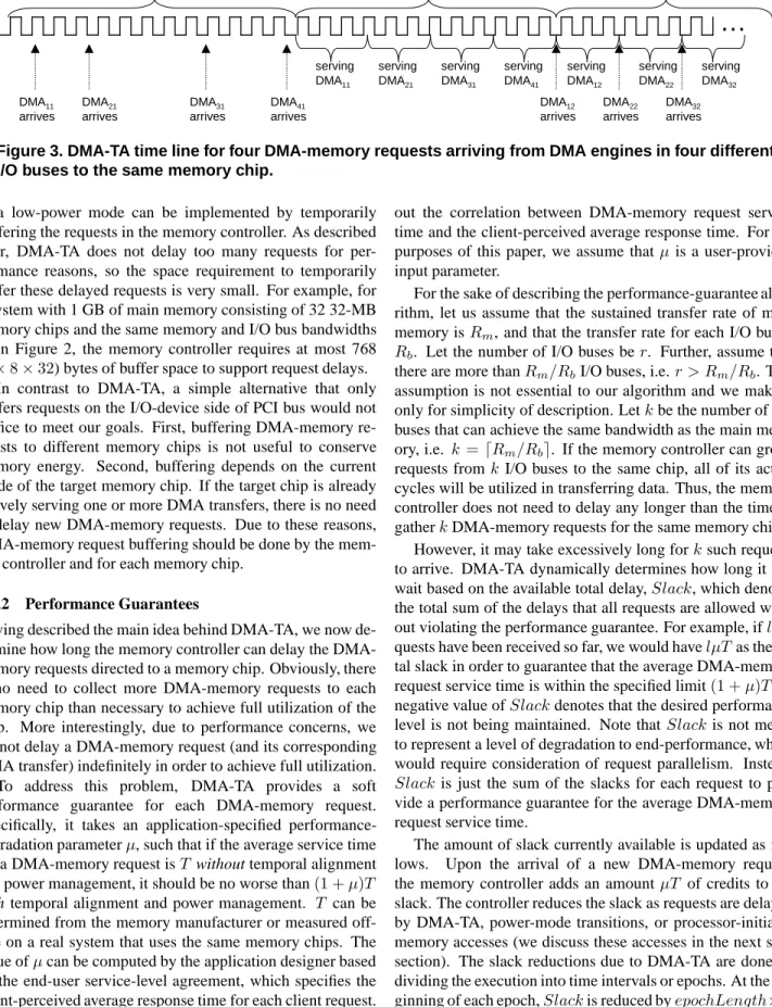
a memory chip in low-power mode, trying to gather enough requests (from other I/O buses) to fully utilize the memory chip active cycles, instead of avoiding power-mode transition-ing as previous works on request batchtransition-ing to reduce disk or network energy consumption [7, 11]. When enough DMA-memory requests have been gathered or the access delay ex-ceeds a threshold value, the controller allows the requests through, enabling the memory chip to service the requests back-to-back. Since the first request of a DMA transfer may be delayed and not immediately acknowledged by the mem-ory controller to the DMA engine, subsequent requests of the same DMA transfer operation will not be issued.
Interestingly, after this first gathering of requests, all sub-sequent requests from the different I/O buses to the chip will be sequenced in lockstep; until the end of the entire DMA transfers, the chip will remain active and requests will not be delayed again. (Similarly, when a new DMA transfer starts while others are already in progress, its requests are not de-layed at all.) The reason is that the time gap between any two adjacent DMA-memory requests of the same DMA transfer is usually fixed as the corresponding DMA engine moves data from or to the memory. As a result, all the DMA transfers be-come properly aligned (interleaved) with each other. This is one of the key differences between DMA-TA and traditional request batching [7, 11].
Figure 3 illustrates the case in which the controller is able to gather enough requests to fully utilize the memory chip. In this example, the first three DMA-memory requests, namely
DM A11,DM A21andDM A31, that arrive from different I/O
buses are not serviced right away; the chip remains in what-ever low-power mode it currently is. When the fourth request,
DM A41, arrives, the memory chip is activated and allowed
to start servicing one request right after the other, wasting no memory cycles. For all these four DMA transfers, subsequent DMA-memory requests,DM Aij(i= 1. . .4andj >1), are in lockstep and are not delayed at all.
…
serving DMA11 serving DMA21 serving DMA41 serving DMA12Managed by low-level energy management policy
DMA11 arrives DMA21 arrives DMA31 arrives DMA41 arrives
Serving all four DMA requests
serving
DMA31
DMA12
arrives
All four DMA transfers are in lock step
DMA22 arrives serving DMA22 serving DMA32 DMA32 arrives
Figure 3. DMA-TA time line for four DMA-memory requests arriving from DMA engines in four different I/O buses to the same memory chip.
in a low-power mode can be implemented by temporarily buffering the requests in the memory controller. As described later, DMA-TA does not delay too many requests for per-formance reasons, so the space requirement to temporarily buffer these delayed requests is very small. For example, for a system with 1 GB of main memory consisting of 32 32-MB memory chips and the same memory and I/O bus bandwidths as in Figure 2, the memory controller requires at most 768 (3×8×32) bytes of buffer space to support request delays.
In contrast to DMA-TA, a simple alternative that only buffers requests on the I/O-device side of PCI bus would not suffice to meet our goals. First, buffering DMA-memory re-quests to different memory chips is not useful to conserve memory energy. Second, buffering depends on the current mode of the target memory chip. If the target chip is already actively serving one or more DMA transfers, there is no need to delay new DMA-memory requests. Due to these reasons, DMA-memory request buffering should be done by the mem-ory controller and for each memmem-ory chip.
4.1.2 Performance Guarantees
Having described the main idea behind DMA-TA, we now de-termine how long the memory controller can delay the DMA-memory requests directed to a DMA-memory chip. Obviously, there is no need to collect more DMA-memory requests to each memory chip than necessary to achieve full utilization of the chip. More interestingly, due to performance concerns, we cannot delay a DMA-memory request (and its corresponding DMA transfer) indefinitely in order to achieve full utilization. To address this problem, DMA-TA provides a soft performance guarantee for each DMA-memory request. Specifically, it takes an application-specified performance-degradation parameterµ, such that if the average service time for a DMA-memory request isT without temporal alignment and power management, it should be no worse than(1 +µ)T
with temporal alignment and power management. T can be determined from the memory manufacturer or measured off-line on a real system that uses the same memory chips. The value ofµcan be computed by the application designer based on the end-user service-level agreement, which specifies the client-perceived average response time for each client request. For example, the application designer can conduct various measurements (using a method similar to that in [2]) to find
out the correlation between DMA-memory request service time and the client-perceived average response time. For the purposes of this paper, we assume thatµ is a user-provided input parameter.
For the sake of describing the performance-guarantee algo-rithm, let us assume that the sustained transfer rate of main memory isRm, and that the transfer rate for each I/O bus is
Rb. Let the number of I/O buses ber. Further, assume that there are more thanRm/RbI/O buses, i.e.r > Rm/Rb. This assumption is not essential to our algorithm and we make it only for simplicity of description. Letkbe the number of I/O buses that can achieve the same bandwidth as the main mem-ory, i.e. k =dRm/Rbe. If the memory controller can group requests fromk I/O buses to the same chip, all of its active cycles will be utilized in transferring data. Thus, the memory controller does not need to delay any longer than the time to gatherkDMA-memory requests for the same memory chip.
However, it may take excessively long forksuch requests to arrive. DMA-TA dynamically determines how long it can wait based on the available total delay,Slack, which denotes the total sum of the delays that all requests are allowed with-out violating the performance guarantee. For example, ifl re-quests have been received so far, we would havelµTas the to-tal slack in order to guarantee that the average DMA-memory request service time is within the specified limit(1 +µ)T. A negative value ofSlackdenotes that the desired performance level is not being maintained. Note thatSlack is not meant to represent a level of degradation to end-performance, which would require consideration of request parallelism. Instead,
Slack is just the sum of the slacks for each request to pro-vide a performance guarantee for the average DMA-memory request service time.
The amount of slack currently available is updated as fol-lows. Upon the arrival of a new DMA-memory request, the memory controller adds an amount µT of credits to the slack. The controller reduces the slack as requests are delayed by DMA-TA, power-mode transitions, or processor-initiated memory accesses (we discuss these accesses in the next sub-section). The slack reductions due to DMA-TA are done by dividing the execution into time intervals or epochs. At the be-ginning of each epoch,Slackis reduced byepochLength×n, wherenis the number of pending DMA-memory requests that are waiting to be serviced andepochLengthis the length of
the epoch. (As we only useepochLengthfor delay account-ing instead of energy management, we find that our results are insensitive to this parameter setting as long as it is not too large.) Intuitively, this approach pessimistically decreases
Slack assuming that all requests will be delayed by the en-tire duration of the epoch. Although a worst-case assumption, it makes sure that DMA-TA will not violate the performance guarantee. Furthermore, this approach obviates the need for the controller to updateSlackafter every request. The slack reductions due to power-mode transitions are done by decreas-ing Slack by the time overhead of activating each memory chip (different chips might be in different power modes) times the number of requests pending for it.
Given the current available slack, DMA-TA can dynami-cally calculate how long a DMA-memory request that finds the corresponding memory chip in low-power mode can wait. Suppose that there are ni pending DMA-memory requests from theith I/O bus fori= 1,2, . . . , r(each pending request coming from an I/O bus has been issued by a different DMA engine attached to the bus). Letm=max{ni |1≤i≤r}. Under these assumptions,U =mTdr/kerepresents an upper bound on the time taken to service all the pending requests. To see this more clearly, recall that each DMA-memory re-quest takesT time when no alignment or power management is performed. Since krequests from different I/O buses can be performed in the way shown in Figure 3,ksuch requests will also take timeT. Next, we can divide all pending DMA-memory requests intodr/kegroups such that requests in each group are from different I/O buses. Since each group has at mostmkrequests, each group can be served inmT time.
Given the value forU, if the memory started to service re-quests now, the average additional delay per pending request would be U/2. (Note that early delays are charged via the epoch-based scheme. Here, we only need to charge the queu-ing delay.) The reason is that the first request serviced would incur zero additional delay, the second one would incurT ad-ditional delay, and so on. Based on this observation, a simple mathematical calculation computes the average additional de-lay ofU/2. Thus, the total delay for allnpending requests would be nU/2. Therefore, the memory chip should start serving requests whennU/2is close to the currentSlackto avoid exceeding the acceptable performance degradation.
Our extensive simulations confirm that this approach en-forces our performance guarantees. In fact, none of the simu-lations discussed in Section 5 violates such guarantees.
4.1.3 Interaction with Accesses from Processors
DMA-TA may interfere with accesses from processors only when the memory chip is servicing DMA-memory requests. More specifically, when requests are aligned to achieve max-imum utilization of the memory-active cycles, there are no cycles left to handle accesses from processors. There are at least a couple of possible solutions to this problem. A simple solution is to always allow accesses from processors to take priority over DMA accesses. In other words, a memory chip
always services accesses from processors first, before servic-ing accesses from DMAs. Another solution is to keep the ac-tive memory cycles at mostx%(e.g. 75%) utilized for DMA-memory requests so that the remaining1−x%(e.g. 25%) is reserved for accesses from processors. In our evaluation, we use the first method.
Regardless of the solution, processor accesses need to be reflected in the remaining amount of available slack for DMA-memory requests. The way we perform these updates is to decreaseSlackby the time it takes for the processor accesses to be serviced times the number of DMA-memory requests pending for the corresponding memory chip.
4.1.4 Complexity and Overheads
DMA-TA can be implemented in memory controllers with even little processing power. Many memory controllers (e.g., the Impulse memory controller [24]) already contain low-power processors. Specifically, DMA-TA needs to count the number of pending DMA-memory requests for each memory chip, which requires only one counter per chip. DMA-TA also needs to maintain a counter for the total available slack, which is updated at the beginning of each epoch and after processor-initiated accesses. Whenever a DMA-memory request arrives that finds the corresponding memory chip in low-power mode, DMA-TA needs to comparenU/2with the current value of
Slackto decide whether the memory chip should start servic-ing all pendservic-ing DMA-memory requests. Such an operation re-quires only one addition and one comparison, sinceU/2can be pre-computed andnU/2can be computed incrementally using one addition every time a new request arrives. Further-more, this overhead is amortized over the large DMA transfer; subsequent DMA-memory requests do not perform this com-parison, since they are serviced right away when the memory chip is already in active mode. Finally, the controller needs a little buffer space for delayed requests.
4.2
Popularity-based Layout
4.2.1 Main Idea
To increase the opportunity for DMA-TA to reduce memory energy waste, our second technique, called Popularity-based Layout (PL), exploits a common access pattern, namely the “20-80 rule” of many data server workloads. Specifically, many of these workloads exhibit considerable skew of ac-cesses towards a small fraction of the blocks. In other words, a majority of accesses are made to a small fraction of the data. For example, Figure 4 shows the access distribution for an OLTP storage DMA transfer trace collected from a real stor-age server. As shown in the figure, around 20% of the pstor-ages account for 60% of the DMA accesses to the main memory of the storage server.
We can exploit this access pattern in workloads by cluster-ing frequently accessed pages in a small subset of the mem-ory chips, so that more concurrent DMA transfers can arrive at such memory chips and the number of isolated transfers at
10 20 30 40 50 60 70 80 90 100 0 10 20 30 40 50 60 70 80 90 100 % of accesses % of pages Popularity of pages
Figure 4. CDF of the popularity of pages in an OLTP storage DMA transfer workload. A point
(x, y)in the curve indicates thatx%of the pages receivey%
of the DMA accesses.
other chips can be reduced. The reason this layout increases the DMA-TA energy savings is that the memory controller can temporally align more DMA-memory requests directed to-wards the “hot” memory chips. Further, the number of DMA-memory requests to “cold” chips is reduced, allowing them to stay in low-power modes for a longer period of time. As a result, the overall memory energy consumption is reduced.
To identify hot pages, our PL technique uses a few bits to keep track of the DMA reference counts (number of accesses by DMAs instead of processors) for each memory page. The reference counts can be maintained either inside the memory controller or as a part of the page table. To adapt to workload changes, these reference bits should be “aged” periodically by either resetting them to zero or right-shifting them by one.
Dynamically, the memory controller can build statistical access distribution histograms to record the percentage of pages with different popularity and the percentage of accesses to pages with different popularity. Based on such histograms, pages can be placed into memory chips according to their popularity values. For example, let N be the total number of memory chips. We divide the memory chips into multiple groups. LetNhotbe the fraction of chips such that if the most popular pages are put in the Nhot chips, they account forp percentage (e.g. 60%) of the total number of DMA-memory requests in the last epoch (time period), wherepis a tunable parameter. The remainingN−Nhotchips comprises the last group, the “cold” group.
For theNhot hot chips, we can further divide them into
K−1groups, namelyG1with only 1 memory chip,G2with 2
chips,G3with 4 chips,. . .,GK−1with2blog(pNhot)c−2chips.
TheK-th groupGK is the cold group. PL associates a pop-ularity ordering among these K groups. We designate that groupGiis more popular thanGjifi < j. Pages are placed into groups according to their popularity values. Our group-ing of pages in PL is a key difference between ours and previ-ous popularity-based layout approaches, e.g. [21].
To adapt to workload changes, memory pages are reorga-nized periodically by the memory controller via page migra-tion. Page migration is based on dividing the execution of the
application into intervals (multiple epochs). At the beginning of each interval, the layout is recomputed to maintain the same invariant. The memory controller follows a simple algorithm to perform the shuffling, such that the number of swaps re-quired is less than or equal to the number of pages which are in a group that does not match their popularity value. Pages that are in the wrong group are migrated to the correct group based on the new layout. For each page migration, its content is first copied into a free page in the destination chip.
To avoid affecting the application, the memory controller and the operating system need to cooperate. A simple method would be for the memory controller to interrupt the proces-sor whenever a page was migrated. The operating system would then update the page table accordingly. However, this approach would involve excessive overhead. To avoid this overhead, the memory controller must store a small table of
< old_location, new_location >page translations. Before the page table is modified, the memory controller simply redi-rects accesses to the old location of a migrated page to its new location. In this approach, the page table would only be mod-ified when the translation table is completely filled or at the end of the current interval. Thus, the cost of the interrupts and the page table updates can be amortized across a number of migrations. In fact, the amount of overhead can be adjusted by increasing/decreasing the size of the translation table or the length of the intervals. By adjusting these parameters, we believe that this overhead can be made negligible, so our sim-ulations do not account for it.
Since page migration incurs energy and time overheads, maintaining a perfectly accurate popularity ordering would be excessively expensive, offsetting the benefit of popularity-based layout. This is one of the reasons that groups are not of equal size. Instead, the sizes of the firstK−1groups follow an exponential curve in order to accommodate the popularity distribution shown in Figure 4. The rationale is that pages accessed 8 times are not necessarily “hotter” than pages that have been accessed 10 times, for example.
Interestingly, we find that using only 2 groups provides the best result in energy conservation given a specified perfor-mance goal, making the PL technique simple to implement with minimum page-migration traffic. The reason is that, with only 2 groups, there are only a hot group for the pages that contribute to appercentage of accesses and a cold group for all remaining pages.
4.2.2 Hiding Migration Energy and Time Overheads
Page migration may interfere with memory accesses from DMAs and processors. One possible optimization is to per-form page migration in small chunks, such as cache-line or 8-byte chunks. The small granularity can leverage those mem-ory cycles during which the involved memmem-ory chips are idle in active mode either waiting for DMA-memory requests or waiting to go down to low-power mode, so that they incur no extra energy and time overhead. Furthermore, the page ac-cesses can be performed by the memory controller itself
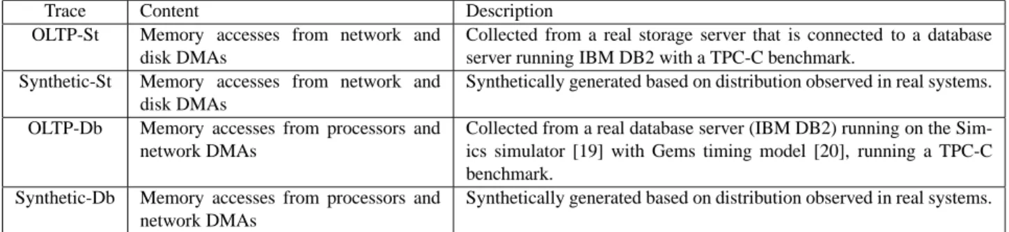
with-Trace Content Description OLTP-St Memory accesses from network and
disk DMAs
Collected from a real storage server that is connected to a database server running IBM DB2 with a TPC-C benchmark.
Synthetic-St Memory accesses from network and disk DMAs
Synthetically generated based on distribution observed in real systems. OLTP-Db Memory accesses from processors and
network DMAs
Collected from a real database server (IBM DB2) running on the Sim-ics simulator [19] with Gems timing model [20], running a TPC-C benchmark.
Synthetic-Db Memory accesses from processors and network DMAs
Synthetically generated based on distribution observed in real systems.
Table 2. Traces used in our evaluation. out involving the processor or any DMA engine. Currently,
these optimizations are still being implemented in our simula-tor. When such optimizations are implemented, we expect our results will be better than those we present in Section 5.
4.2.3 Complexity and Overhead
Similar to DMA-TA, PL can also be implemented in a sim-ple way by smart memory controllers. The memory controller needs to use a counter to record the number of DMA-memory requests for each page during an interval. To reduce the space requirement of these counters, we can increase the granularity from a page to a memory region which may consist of tens (e.g. 32) of pages. Also, we can remember the access counter for only those recently accessed pages. These methods are likely to work well since DMA transfers are usually at large granularity with good temporal locality in memory addresses. Each DMA-memory request requires a hash-based lookup by the memory controller to find and increment the correspond-ing page’s reference counter. Since subsequent requests of the same DMA transfer are typically for the same page, a few re-cently accessed counters can be kept in a small cache as short-cuts for fast lookups and increments.
Finally, the memory controller needs to implement the mi-gration algorithm and the table of page translations. The al-gorithm only runs at the beginning of an interval. The table of translations is similar to equivalent structures in previously proposed smart memory controllers [24].
5
Evaluation Results
5.1
Methodology
We evaluate our DMA-aware memory energy management techniques using an accurate trace-driven simulator that inte-grates several component-based simulators including: (1) the widely used disk-array simulator DiskSim [10], which models disk accesses very accurately; (2) a trace-driven main mem-ory simulator that models both timing and energy based on the latest 512-Mb 1600-MHz RDRAM specification shown in Table 1; and (3) a network and disk DMA simulator. The sim-ulated system has 32 memory chips. We simulate three 133-MHz 64-bit PCI-X buses attached to the memory bus. The default DMA-memory request size is 8 bytes, whereas the de-fault number of groups for PL is 2. Our simulator is driven by
memory access traces that include accesses from both proces-sors and DMAs.
We use two sets of traces, each set representing a differ-ent type of workload. The first set includes two memory ac-cess traces representing memory workloads of storage servers. These traces contain accesses from network and disk DMAs only, because the processor in a typical storage server does not do any processing of the data requested by clients. The second set includes two memory access traces representing memory workloads of database servers, which contain mem-ory accesses from both processors and network DMAs. The processor accesses are for 64-byte cache lines. Each set in-cludes a trace collected from a real system and a synthetically generated trace. The OLTP-St trace contains network and disk DMA operations at average rates of 45.0 transfers/ms and 16.7 transfers/ms, respectively. The OLTP-Db trace has network DMA operations and processor accesses at average rates of 100.0 transfers/ms and 23,300 accesses/ms, respectively. The synthetic traces assume a Zipf distribution of page popularity withα= 1, a Poisson DMA transfer arrival rate with an av-erage of 100 transfers/ms, and a Poisson processor access rate with an average of 10000 accesses/ms (Synthetic-Db only). The synthetic traces allow us to easily vary the characteristics of the workloads, as we do in Section 5.4. Table 2 summarizes the characteristics of the four traces.
In our simulations, the dynamic memory energy manage-ment scheme [16] is always used as the low-level memory ergy management policy. Most of our results show the en-ergy savings when this low-level policy is enhanced with our DMA-aware energy management techniques. For this reason, we refer to the system using the low-level policy only as the “baseline” in this section.
Our results show the behavior of our techniques with re-spect to the baseline, focusing on the effect of the acceptable performance degradation, the workload intensity, the number of processor-initiated memory accesses per DMA transfer, and the ratio between memory and I/O transfer rates.
It is important to note that from now on we express the acceptable performance degradation as the limit on the client-perceived average response time degradation. As such, we refer to it as CP-Limit. CP-Limit is a more intuitive and meaningful value thanµ (the acceptable degradation in the
-40 -20 0 20 40 60 80 0 5 10 15 20 25 30 35 40 45 50
% energy savings over the baseline
CP-Limit(%) DMA-TA DMA-TA-PL with 2 groups DMA-TA-PL with 3 groups DMA-TA-PL with 6 groups
-40 -20 0 20 40 60 80 0 5 10 15 20 25 30 35 40 45 50
% energy savings over the baseline
CP-Limit(%) DMA-TA DMA-TA-PL with 2 groups DMA-TA-PL with 3 groups DMA-TA-PL with 6 groups
-40 -20 0 20 40 60 80 0 5 10 15 20 25 30 35 40 45 50
% energy savings over the baseline
CP-Limit(%) DMA-TA DMA-TA-PL with 2 groups DMA-TA-PL with 3 groups DMA-TA-PL with 6 groups
-40 -20 0 20 40 60 80 0 5 10 15 20 25 30 35 40 45 50
% energy savings over the baseline
CP-Limit(%) DMA-TA DMA-TA-PL with 2 groups DMA-TA-PL with 3 groups DMA-TA-PL with 6 groups
(a) OLTP-St (b) Synthetic-St (c) OLTP-Db (d) Synthetic-Db
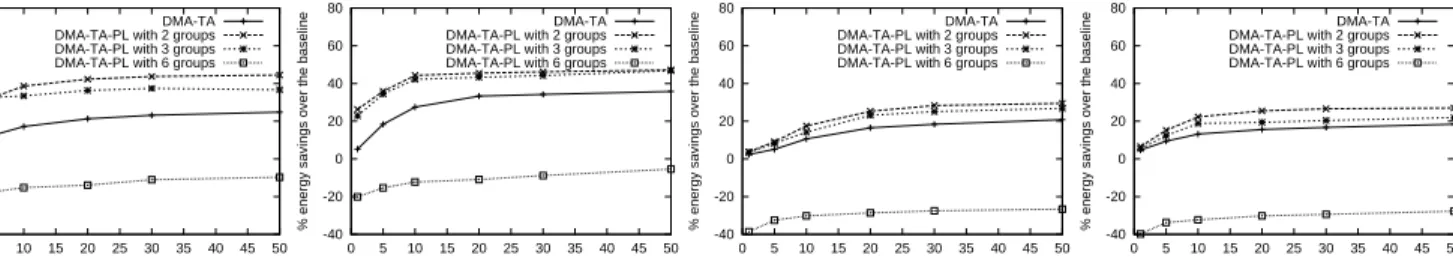
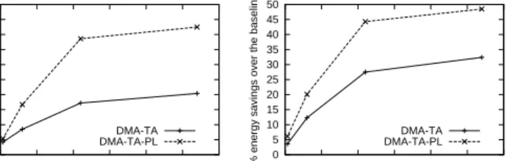
Figure 5. Memory energy savings by the DMA-aware techniques compared to the baseline low-level energy management. The X-axis denotes the maximum client-perceived average response time degradation, whereas the Y-axis shows the percentage of energy saving over the baseline (the dynamic energy management scheme [16]). The curves labeled “DMA-TA” show the results for DMA-TA only, whereas those labeled “DMA-TA-PL” show the results when both of our techniques are used.
average response time of each DMA-memory request), the ac-tual parameter that DMA-TA takes. We transform CP-Limit intoµoff-line by determining how much each DMA-memory request would have to be slowed down to achieve a client-perceived degradation of CP-Limit. Our results show that our techniques never violate CP-Limit.
5.2
Overall Results
Figure 5 shows the percentage energy savings of our DMA-aware techniques as a function of CP-Limit, compared to a system that only uses the baseline policy. The graphs show re-sults for DMA-TA-PL (the combination of DMA-TA and PL schemes) using various numbers of popularity groups. All re-sults for the DMA-TA and PL schemes provide performance degradation within the specified CP-Limit limit. (Due to space limitations, we do not show the actual performance degrada-tion results here.) Because baseline does not provide any per-formance guarantees, our techniques’ results are always com-pared to the same baseline result.
From these graphs, it is clear that our DMA-aware tech-niques can conserve significantly more energy than a memory energy management policy that is oblivious to DMA trans-fers. For example, DMA-TA-PL (with 2 groups) results in 38.6% less energy consumption than the baseline for a maxi-mum 10% client-perceived response time degradation for the OLTP-St workload. The reason is that DMA-TA-PL is very effective at temporally aligning DMA transfers, thereby re-ducing the amount of memory energy waste.
The results also show that DMA-TA-PL is very effective at increasing the energy savings with respect to DMA-TA alone. Take the OLTP-St workload as an example. DMA-TA alone can achieve only moderate (6-24.8%) energy savings over the baseline, whereas DMA-TA-PL can provide high (19.4-44.5%) energy savings. The reason is that PL significantly increases the opportunity for TA to gather more DMA-memory requests to “hot” chips.
Interestingly, our results indicate that PL behaves best with just 2 groups. Considering the OLTP-St workload and a CP-Limit of 10% for example, we can see that DMA-TA-PL with 2 groups provides 38.6% energy savings over the baseline,
whereas it achieves only 33.4% and -15.2% savings with 3 and 6 groups, respectively. This effect is caused by the energy and time overheads of page migration. With more groups, the amount of page shuffling increases, offsetting the benefit of PL. For this reason, from now on we only present DMA-TA-PL results for 2 groups.
It is also important to note that, as CP-Limit increases, both DMA-TA and DMA-TA-PL conserve increasingly more en-ergy. This result was expected, since DMA-TA can delay DMA-memory requests for a longer time, trying to gather more of them. The increases in energy savings are substan-tial up to 10% performance degradation. Beyond this point, the energy savings increase much more slowly. The reason is that, after enough requests have been gathered to achieve maximum memory utilization, there is no benefit in delaying requests longer. This behavior is actually quite different from those of the request batching approaches studied in previous work for processor or disk energy management.
Finally, these results show that our techniques behave well regardless of whether the workload includes processor-initiated memory accesses. In particular, the results for OLTP-Db and Synthetic-OLTP-Db show lower but still significant energy savings, especially for DMA-TA-PL with 2 groups. Energy savings are lower for database servers than for storage servers, because processor-initiated accesses in the former servers con-sume some of the idle cycles when the memory is active be-tween DMA-memory requests. Overall, the trends we see are exactly the same in both types of servers. For this reason, the following subsections focus only on storage servers.
5.3
Analysis of Results
To further understand the reasons behind the energy sav-ings produced by our techniques, we compare the memory energy breakdowns of the baseline, DMA-TA, and DMA-TA-PL schemes for 10% CP-Limit. As shown in Figure 6, while the active energy spent on serving requests remains the same, there is a significant reduction in the energy wasted when chips are active but idle between successive DMA-memory requests. As an additional benefit from our DMA-TA and PL
Figure 6. Energy breakdowns of OLTP-St with 10% CP-Limit. Each energy component has the same meaning as in Figure 2(b), except for the migration energy of DMA-TA-PL. 0 0.2 0.4 0.6 0.8 1 0 5 10 15 20 25 30 35 40 45 50 Utilization Factor CP-Limit(%) DMA-TA DMA-TA-PL
Figure 7. Utilization factors of DMA-TA and DMA-TA-PL for OLTP-St with 10% CP-Limit. techniques, the number of power-mode transitions is also de-creased, which leads to reduced transition energy. However, this effect is essentially negligible in our results.
Comparing DMA-TA-PL with DMA-TA, we can see that the former technique reduces the waste of active energy fur-ther than the latter one. In fact, it is interesting to see that the energy overhead of migration is more than offset by the reduction in active energy waste.
As the main benefit of DMA-TA and PL comes from in-creased concurrency and improved utilization of active mem-ory cycles, we introduce a metric to measure these effects ex-plicitly, the utilization factor (uf):
uf =Tusef ul
Ttot
whereTtotis the total amount of time during which some DMA transfer is in progress and so the accessed memory chips are in the active mode. This includes the time between suc-cessive DMA-memory requests for a given transfer operation.
Tusef ulis the time during which the memory is actually serv-ing some DMA-memory request. For example, if the memory transfer rate is three times the transfer rate of the I/O bus and no two DMA-memory requests are interleaved,uf = 0.33. Clearly, the maximum value ofufis 1.
Figure 7 shows the utilization factors of DMA-TA and TA-PL, as a function of CP-Limit. Without our DMA-aware techniques, the utilization factors are only around 0.33, which means that 67% of the active memory energy is wasted. In contrast, with DMA-TA-PL, the utilization factors of OLTP-St are improved to 0.63 with 10% CP-Limit and 0.75 with 30% CP-Limit. These results indicate an improved
uti-0 10 20 30 40 50 60 0 50 100 150 200 250 300
% energy savings over the baseline
DMA transfer rate(transfers/ms) DMA-TA DMA-TA-PL
Figure 8. Energy savings as a function of workload intensity for Synthetic-St.
0 5 10 15 20 25 30 35 40 45 50 1 10 100 1000
% energy savings over the baseline
Number of processor accesses per DMA transfer DMA-TA DMA-TA-PL
Figure 9. Energy savings as a function of number of processor accesses per DMA transfer for Synthetic-Db.
lization of active cycles. Similar to the energy savings of Fig-ure 5, the utilization factors increase rapidly with CP-Limit at first, but more slowly for CP-Limits larger than 10%.
5.4
Sensitivity Analysis
This subsection evaluates the sensitivity of our techniques to workload and hardware characteristics. We use 10% CP-Limit and our default parameters, unless otherwise specified.
Workload intensity. Figure 8 shows the effect of varying the workload intensity of the Synthetic-St trace. We vary the intensity by varying the average DMA transfer arrival rate. Recall that our default average arrival rate in this synthetic trace is 100 transfers/ms. The results show that DMA-TA and DMA-TA-PL can save more energy over the baseline for more intensive workloads. The reason is that more intensive workloads provide more opportunity for request aligning to reduce active energy waste. As one would expect, the benefit of DMA-TA and PL increases more slowly at higher intensi-ties, since some DMA transfers are already naturally aligned in the baseline system at those intensities.
Intensity of processor accesses. A comparison between the storage and database server results in Figure 5 shows that processor-initiated accesses reduce the energy savings achiev-able by our techniques. These accesses consume some of the active idle energy that our techniques seek to eliminate.
Figure 9 illustrates this effect more clearly. The figure shows the energy savings produced by TA and DMA-TA-PL, as a function of the number of processor accesses
0 5 10 15 20 25 30 35 40 45 50 1 2 3 4 5 6 7
% energy savings over the baseline
Ratio of memory to I/O bandwidth DMA-TA DMA-TA-PL 0 5 10 15 20 25 30 35 40 45 50 1 2 3 4 5 6 7
% energy savings over the baseline
Ratio of memory to I/O bandwidth DMA-TA DMA-TA-PL
(a) OLTP-St (b) Synthetic-St
Figure 10. Energy savings as a function of the ratio between memory and I/O bus bandwidth. (each to a 64-byte cache line) per DMA transfer. To gener-ate the figure, we injected different numbers of processor ac-cesses per DMA transfer into Synthetic-Db. The figure shows that indeed energy savings drop significantly with an increase in processor accesses. However, even when the number of accesses is in the hundreds, the energy savings are still sig-nificant. For comparison, the OLTP-Db trace collected from a commercial database server (IBM DB2) has an average of 233 processor accesses per DMA transfer.
Ratio of memory and I/O transfer rates. Finally, we study the effect of the ratio between memory and I/O transfer rates. Recall that the results above assume that the I/O bus band-width is 1 GB/s (the bandband-width of the PCI-X bus), and that memory can transfer data at rate of 3.2 GB/s (the data rate of RDRAM). So the ratio between the two is around 3.
Figure 10 shows the results for OLTP-St and Synthetic-St. To vary the ratio, we kept the memory bandwidth fixed at 3.2 GB/s and varied the I/O bus bandwidth (0.5 GB/s, 1 GB/s, 2GB/s, and 3 GB/s). When the ratio is close to 1, i.e. the memory and the I/O bus have about the same transfer rate, DMA-TA and PL provide small (around 5%) energy savings, which is expectable. As we increase the ratio, the amount of energy conserved by DMA-TA and DMA-TA-PL also quickly increases, since the active energy waste starts to dominate. Because PL provides greater opportunities to align requests, DMA-TA-PL improves faster than DMA-TA for higher ratios.
6
Related Work
This section discusses closely related works that are not de-tailed in earlier sections. The discussion is divided into works that relate to memory energy management in general, tempo-ral alignment, and popularity-based layouts in the main mem-ory and disks.
Memory energy management. In addition to the works de-scribed in Sections 1 and 2, Fan et al. have investigated mem-ory controller policies for determining chip power states based on the estimated idle time between accesses [9]. Delaluz et al. have studied compiler-directed [5] and operating-system-based approaches [3] to conserve memory energy. Recently, Huang et al. proposed a power-aware virtual memory
imple-mentation to conserve memory energy [12]. Li et al. consid-ered performance-directed memory energy management [18]. Zhou et al. proposed using applications’ miss ratio curves to direct memory energy management [25].
Our work differs from these prior works in that it focuses on DMA-aware memory energy management, which is neces-sary to conserve memory energy in data servers.
Temporal Alignment. Our DMA-TA technique shares some similarity to request batching used in disk energy man-agement [11] and processor energy manman-agement [7]. For ex-ample, in [7], the requests sent to a Web server are batched by the network interface card to increase host processor idle times. DMA-TA differs from these works in two respects: (1) Previous works batch request to minimize the energy and time spent in powering devices up and down, whereas our tech-niques increase the level of concurrency in DMA transfers by sequencing multiple DMA operations in lockstep to reduce the amount of energy waste due to the mismatch between memory and I/O bus bandwidths; and (2) In previous works, it is typi-cally beneficial to batch as many requests as possible as long as performance is not significantly affected. In our techniques, batching more requests than the maximum level of concur-rency supported by the memory device has little benefit, since the energy cost for transitioning between power modes is neg-ligible compared to the energy consumption of a large DMA operation, as we explain in Section 3.
Popularity-based Layout. Lebeck et al. have conducted a preliminary investigation of popularity-based layouts to allow some memory devices to stay in low-power modes for a longer time [16]. Their results for SPEC benchmarks showed that a popularity-based layout is not very helpful. Therefore, they did not propose or evaluate a realistic popularity-based layout strategy. Delaluz et al. have studied compiler and operating-system-based strategies to place frequently accessed data to-gether in a few memory modules again for scientific applica-tions [3, 4, 5, 6]. A similar idea has been explored by Pin-heiro and Bianchini in the context of disk array energy man-agement [21], where popular files are migrated to a subset of disks to skew the workload, and thus allow the remaining disks to conserve energy.
Unlike the works that use popularity-based layouts to cre-ate skewed loads on devices, we use such layouts for a differ-ent purpose: to increase the opportunity for temporal align-ment of DMA operations for data servers. As such, our PL technique can be relatively simple and incur only small overheads. Further, while previous work on popularity-based memory layouts follows a strict popularity-based ordering, our PL technique uses a logarithmic order based on the popu-larity distribution characteristics of real workloads.
7
Conclusion
To the best of our knowledge, this paper is the first to study memory energy management for DMA-initiated mem-ory accesses. These accesses have different characteristics and
implications for energy management than processor-initiated accesses. We characterized the effect of DMA accesses on memory energy and showed that, due to the mismatch be-tween memory and I/O bus bandwidths, significant energy is wasted when memory is idle but still active during large DMA transfers. To reduce this waste, we proposed two novel performance-directed energy management techniques, tempo-ral alignment and popularity-based layout, which increase the level of concurrency between multiple DMA transfers from different I/O buses to the same memory chip. Our results on a detailed trace-driven simulator with storage and database server traces showed that our techniques can effectively min-imize the amount of idle energy waste during DMA transfers and, consequently, conserve as much as 38.6% more memory energy than previous approaches for only a small degradation in performance.
Since memory accesses from DMAs are dominant in data servers such as storage and database servers, our work takes a significant step forward in memory energy management for these servers, an important class of applications in which en-ergy consumption is one of the major concerns.
We envision several directions for future work. First, we plan to conduct run-time cost-benefit analysis before page mi-gration, so that migration is performed only when it is benefi-cial. Second, we will explore other workloads, such as TPC-H workloads, and evaluate them in a whole-system simulator that can run a real commercial database server. Third, we are in the process of investigating the optimizations described in Section 4.2 to reduce migration overheads.
References
[1] F. Catthoor, S. Wuytack, E. D. Greef, F. Balasa, L. Nachtergaele, and A. Vandecappelle. Custom memory management methodology explo-ration of memory organization for embedded multimedia systems de-sign. In Kluwer Academic Publishers, 1998.
[2] I. Cohen, J. S. Chase, M. Goldszmidt, T. Kelly, and J. Symons. Cor-relating instrumentation data to system states: A building block for automated diagnosis and control. In Proceedings of the International Symposium on Operating Systems Design and Implementation (OSDI), pages 231–244, December 2004.
[3] V. Delaluz, M. Kandemir, and I. Kolcu. Automatic data migration for reducing energy consumption in multi-bank memory systems. In Pro-ceedings of the 39th Design Automation Conference, pages 213–218, June 2002.
[4] V. Delaluz, M. Kandemir, N. Vijaykrishnan, and M. J. Irwin. Energy-oriented compiler optimizations for partitioned memory architectures. In Proceedings of the International Conference on Compilers, Archi-tecture, and Synthesis for Embedded Systems, pages 138–147, August 2000.
[5] V. Delaluz, M. Kandemir, N. Vijaykrishnan, A. Sivasubramniam, and M. J. Irwin. Hardware and software techniques for controlling dram power modes. IEEE Transactions on Computers, 50(11), 2001. [6] V. Delaluz, A. Sivasubramaniam, M. Kandemir, N. Vijaykrishnan, and
M. J. Irwin. Scheduler-based dram energy management. In Proceedings of the 39th Design Automation Conference, pages 697–702, June 2002.
[7] E. Elnozahy, M. Kistler, and R. Rajamony. Energy conservation poli-cies for web servers. In Proceedings of the 4th USENIX Symposium on Internet Technologies and Systems, March 2003.
[8] EMC Symmetrix DMX 3000 Specification Sheet. http://www.emc.com/products/systems/symmetrix/symmetri
_DMX1000/pdf/DMX3000.pdf, April 2005.
[9] X. Fan, C. Ellis, and A. Lebeck. Memory controller policies for dram power management. In Proceedings of the International Symposium on Low Power Electronics and Design, pages 129–134, August 2001. [10] G. R. Ganger, B. L. Worthington, and Y. N. Patt. The DiskSim
simula-tion environment - version 2.0 reference manual, December 1999. [11] T. Heath, E. Pinheiro, J. Hom, U. Kremer, and R. Bianchini.
Appli-cation transformations for energy and performance-aware device man-agement. In Proceedings of the International Conference on Parallel Architectures and Compilation Techniques, pages 121–130, September 2002.
[12] H. Huang, P. Pillai, and K. G. Shin. Design and implementation of power-aware virtual memory. In Proceedings of the USENIX Annual Technical Conference, pages 57–70, June 2003.
[13] IBM eServer p5 595 Model 9119-595 Executive Sum-mary. http://www.tpc.org/results/individualresults/IBM/IBM _595_64_20041118_ES.pdf, May 2005.
[14] Intel chipsets. http://www.intel.com/products/server/chipsets/index.htm. [15] M. T. Kandemir, N. Vijaykrishnan, M. J. Irwin, and W. Ye. Influence of compiler optimizations on system power. In Proceedings of the 37th Design Automation Conference, June 2000.
[16] A. R. Lebeck, X. Fan, H. Zeng, and C. S. Ellis. Power aware page allocation. In Proceedings of the International Conference on Archi-tectural Support for Programming Languages and Operating Systems (ASPLOS), pages 105–116, November 2000.
[17] C. Lefurgy, K. Rajamani, F. Rawson, W. Felter, M. Kistler, and T. W. Keller. Energy management for commercial servers. IEEE Computer, 36(12):39–48, December 2003.
[18] X. Li, Z. Li, F. M. David, P. Zhou, Y. Zhou, S. V. Adve, and S. Ku-mar. Performance directed energy management for main memory and disks. In Proceedings of the 11th International Conference on Archi-tectural Support for Programming Languages and Operating Systems (ASPLOS), pages 271–283, October 2004.
[19] P. S. Magnusson, M. Christensson, J. Eskilson, D. Forsgren, G. Hall-berg, J. HogHall-berg, F. Larsson, A. Moestedt, and B. Werner. Simics: A full system simulation platform. IEEE Computer, 35(2):50–58, 2002. [20] M. M. Martin, D. J. Sorin, B. M. Beckmann, M. R. Marty, M. Xu, A. R.
Alameldeen, K. E. Moore, M. D. Hill, and D. A. Wood. Multifacet’s general execution-driven multiprocessor simulator (gems) toolset. In Computer Architecture News, 2005.
[21] E. Pinheiro and R. Bianchini. Energy conservation techniques for disk array-based servers. In Proceedings of the International Conference on Supercomputing, July 2004.
[22] Rambus. RDRAM. http://www.rambus.com, 1999.
[23] Storage Systems Division. Adaptive power management for mobile hard drives. IBM White Paper, 1999.
[24] L. Zhang, Z. Fang, M. Parker, B. Mathew, L. Schaelicke, J. Carter, W. Hsieh, and S. McKee. The impulse memory controller. IEEE Trans-actions on Computers, Special Issue on Advances in High Performance Memory Systems, pages 1117–1132, November 2001.
[25] P. Zhou, V. Pandey, J. Sundaresan, A. Raghuraman, Y. Zhou, and S. Ku-mar. Dynamic tracking of page miss ratio curve for memory manage-ment. In Proceedings of the 11th International Conference on Archi-tectural Support for Programming Languages and Operating Systems (ASPLOS), October 2004.